Assignment 2-RADIOSS Engine File Editing & 3D Meshing Challenge
#11 // Assignment 2_RADIOSS Engine File Editing & 3D Meshing Challenge.
AIM: To study about the starter file and engine file in RADIOSS by changing the parameters for the given file. And also perform a 3D meshing on the HOUSING MODEL which one will have tetra mesh and ARM BRACKET have hex mesh.
OBJECTIVE:
1/ Check the material properties of the rail component and calculate the speed of sound in steel rail
2/ The length of the rail is about 1000 mm. calculate the time takes for a shock wave to travel from one end of the rail to the other.
3/ Time for sound to travel the length of the rail
4/ Edit the engine file so that the stress wave can be monitored, moving from one end of the rail to the other during an impact -this will require a termination time equal to the time it takes for the sound to travel the length of the rail (set on/RUN card)
5/ Set the frequency of animation output to a time that will give 20 animation steps(/ANIM/DT)
6/ Change /print -10.
7/ 3d meshing tetra mesh and hex mesh
- Repeat class examples and, maintain the quality.
- Target tet size=5mm, hex size= 10mm, tet collapse= 0.15.
PROCEDURE / SOLUTIONs:
1. Check the material properties of the rail component and calculate the speed of sound in steel rail.
- So, to check the material properties of the material of the rail component. We have to import the component in the hypermesh.
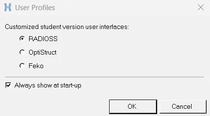
- We have the ".rad" file. So, for that, the profile should be RADIOSS.
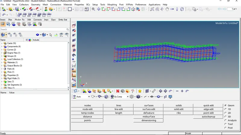
- Now we will go to the import option. There we are going to select the 0000.rad file and import it.
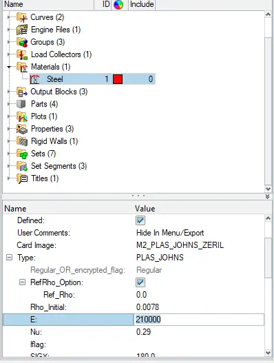
- Now we will go to material property and check the values.
- Speed of sound (c) =`( E /ρ ) ^(1/2)`
- where E = Young's modulus
- ρ">ρ = density
- Ref_Rho 0.0
- Rho_initial 0.0078
- Nu 0.29
- So, speed of sound (c) = `(21000/0.0078)^(1/2)` = 5188.745 m/s.
-
2. The length of the rail is about 1000 mm calculate the time takes for a shock wave to travel from one end of the rail to the other.
- Shock wave travels at the speed of sound.
- So, Shock wave speed = speed of sound = 5188.745 m/s.
- Time (t)=`(Distance/speed)`=`1000/5188.745`=0.1927
3. Time for sound to travel length of rail= 0.1927 ms
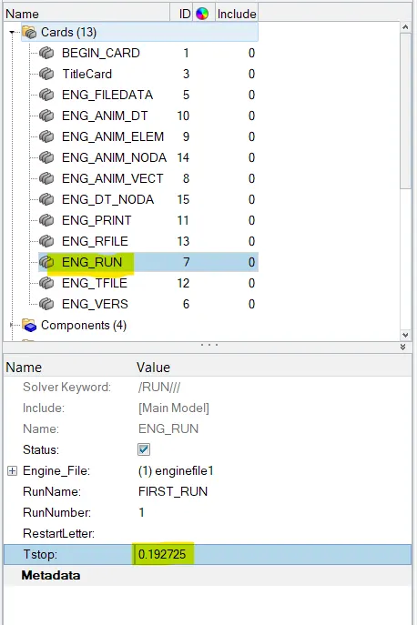
we change the value in the hypermesh itself. There we go to the ENG_RUN card. There we change the Tstop value. There we have to give the value to be 0.1927 and after that, we have to run the file. So, it will change the values in the 0001.rad file itself.
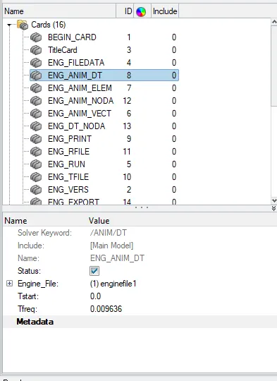
5. Set the frequency of animation output to a time that will give 20 animation steps(/ANIM/DT).
frequency =`Time/no of revolution`=`0.1927/20`=0.009636
we change the value in the hypermesh itself. There we go to the ENG_ANIM_DT card. There we change the ‘Tfreq’ value. There we have to give the value to be 0.009636 and after that, we have to run the file. So, it will change the values in the 0001.rad file itself.
6. Change /print -10
we change the value in the hypermesh itself. There we go to the ENG_PRINT card. There we change the ‘N_print’ value. There we have to give the value to be ' -10 ' and after that, we have to run the file. So, it will change the values in the 0001.rad file itself.
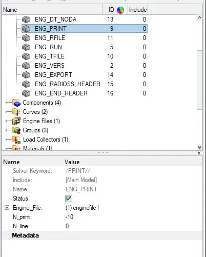
- We can see that the by default PRINT value is -10. So, there is no need to change that.
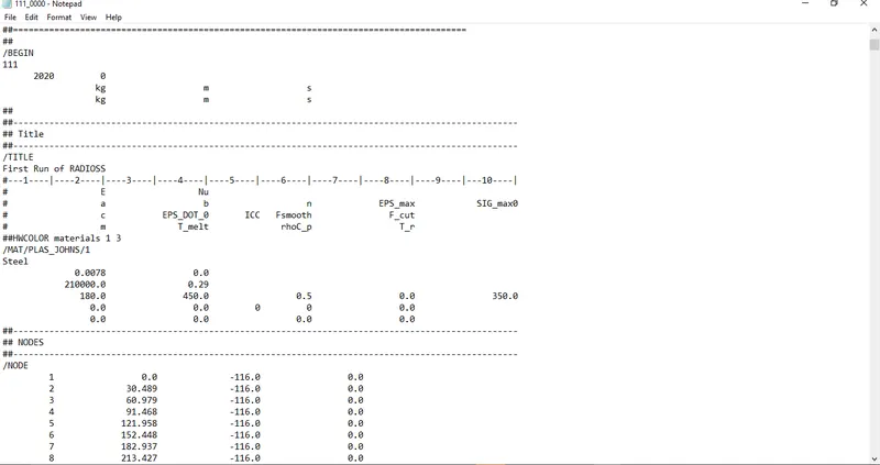
- Also, we can analysis starter file as 0000.rad file in notepad for boundary conditions, unit systems of materials & property,etc.
// DEPLOYING 1D ELEMENTS BETWEEN TWO PLATES.
OBJECTIVES ->
- To import the model.
- To mesh the model.
- To deploy rigid, bar, beam, and spring elements between the two meshed square plates.
PROCEDURE ->
- 1d elements are basically used to reduce the computational time. An object can mesh with 1D, 2D, or 3D elements, however, if it is possible to deploy 1D elements, then it should be always preferable. It is because the more the number of nodes, the more computational time to simulate the model.
- 1D elements are also used to make connections between different components. If two components have to be connected but no geometry is available to mesh, simply putting the 1D elements there would represent the connection. Thus, no need for geometry is required in such cases.
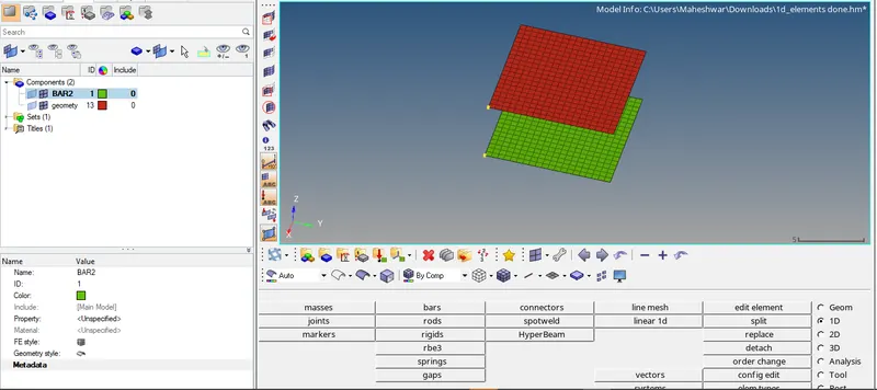
- In this assignment, a model was available as shown in figure below. From the figure, it can be observed that one square plate has meshed while one is not. So, to deploy 1D elements, the other plate also had to meshed. The length of the element on the meshed square plate was 0.5 units. Thus, using Geom > 2D > auto mesh, the other plate also meshed with the element length of 0.5 units,
- Now, when the parts mesh, it is always better to assign it the material and the property. Therefore, a material card was created, providing it the property of steel, and the property card was created, providing it the thickness of 1 unit. Both of these cards were assigned to the available components. Now, when the components mesh, and all set with properties, it is ready to get deployed with 1D elements.
RBE2 and RBE3 Elements ->
- There are two types of elements used to represent a rigid connection viz. RBE2 and RBE3 elements. The property of connection with the RBE2 element is that there is a single master node (or independent node) and multiple slave nodes (or dependent nodes). It means when multiple nodes are selected as slave nodes, and given one master node, the master would be the centre of mass/load of all the slave nodes.
- All the load that is coming on the master node, the same load would be transferred to the slave nodes. However, using RBE3 elements, there can be multiple master nodes and a single slave node, which means whatever load that is coming on the slave node would be distributed among all the master nodes.
- Another difference between them is that RBE2 provides tremendous stiffness however RBE3 element does not provide the stiffness but distributes it to the neighbouring nodes. Therefore, when infinite rigidity is required RBE2 element is used and when little deformation is also needed to be seen RBE3 element is used. Using 1D > rigid, an RBODY creates.
- meshed plates connected with a rigid RBE3 element.
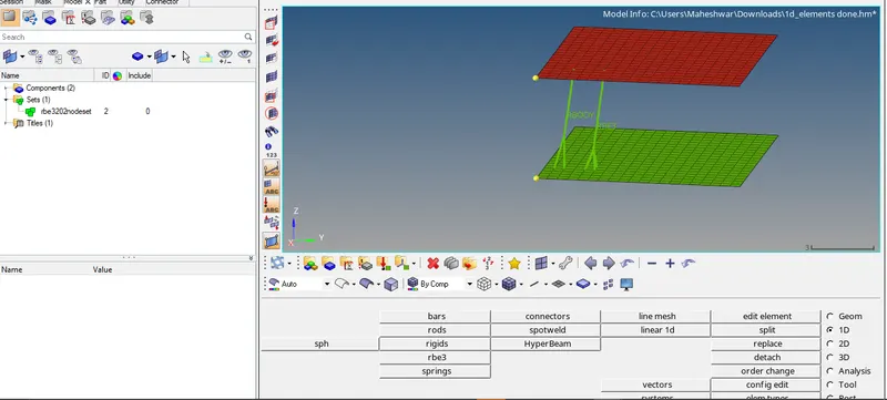
ROD or Truss Element ->
- Bar and Rod are those straight members that can be only subjected to axial loadings like tension or compression, but not bending or torsion. The cross-section of the rod is always circular.
- however, the cross-section of bar and beam can be of any circular or non-circular shape. Thus, if a member is subjected to any transverse load, it is called the beam, and if it is subjected to only axial loads, then it is called a bar.
- Moreover, if any single transverse load is applied to the bar, it is no more called a bar, it would be called a beam. Now, to deploy the rod element in the model, 1D > rods is the path. The truss element gets create after selecting the two nodes.
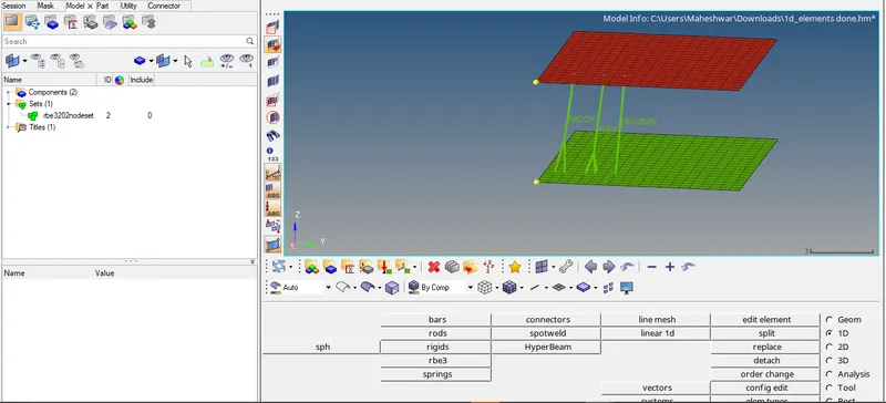
Beam Element ->
- The member which is subjected to any transverse load is called the beam. The beam can be of any shape. Using 1D > bars, the beam element was created.
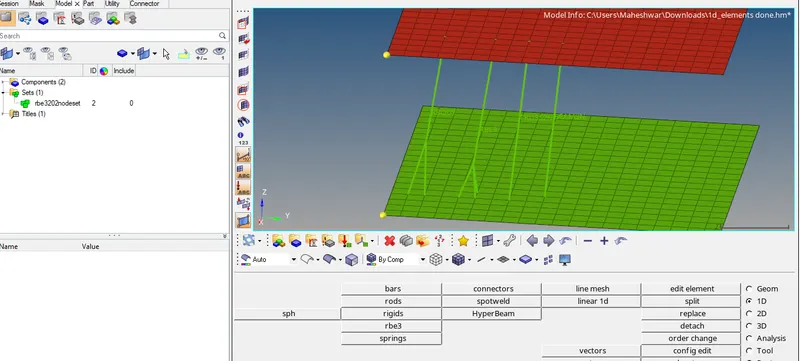
Spring Element ->
- The spring can be two-noded or three-noded, four-noded. In this model, the two noded spring is created using 1D > springs.
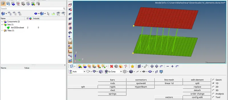
- The final image of the model with all the 1D elements deployed.
7 .3d meshing tetra mesh and hex mesh.
- Repeat class examples and, maintain the quality.
- Target tet size=5mm, hex size=10mm, tet collapse=0.15.
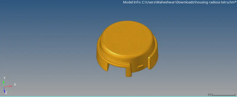
3D Meshing TETRA mesh (Housing model) ->
Methods to generate Tetra Meshing:
There are three methods to generate Tetra Meshing as stated below:
- Conversion of 2D tria to Tetrahedral Elements, by using Tetra Mesh panel.
- Using the Quick Tetra Mesh, from the Utility panel.
- Using the Volume Tetra Mesh panel.
/1) Conversion of 2D Tria Elements into Tetrahedral Elements, by using Tetra Mesh panel ->
Steps to be followed to generate Tetra Mesh:
- Import the Model into HyperMesh and clean the geometry.
- Delete the solid from the model, by selecting the Delete > Solid > Delete entity.
- Now perform the 2D meshing on the model, by selecting the Mesh type as “Trias”.
below figure shows deploying 2D mesh on the Housing model.
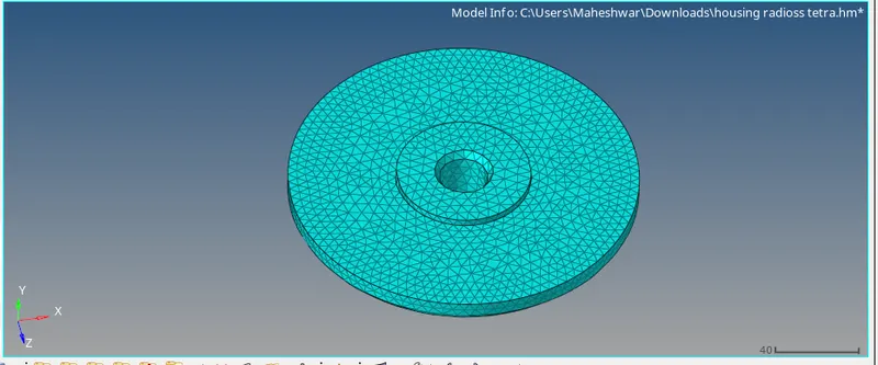
- After completing the 2D meshing, the model should be cleared with the Minimum and Maximum Elemental error
- Now the model is ready to perform the Tetra Meshing. Select the 3D > tetramesh option.
- In the tetra mesh panel, select the elements under the “Fixed trias/quads to tetra mesh” option
- After selecting the elements, click on the “Mesh” button.
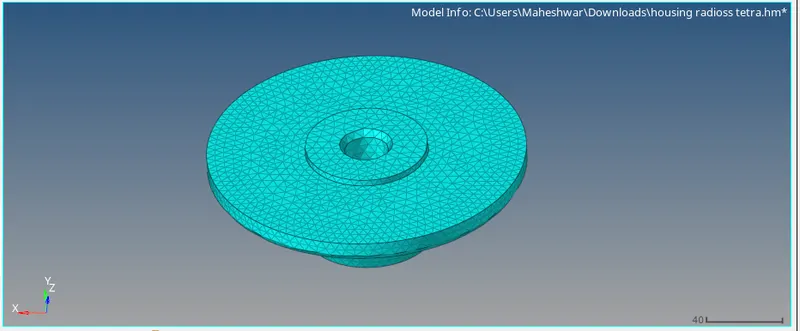
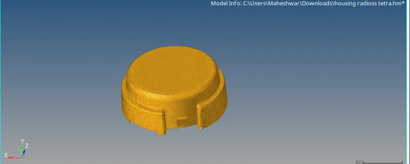
> Housing Model after creating Tetra Mesh ->
Once the Tetra Meshing was completed, mask a few elements to check the mesh generation.
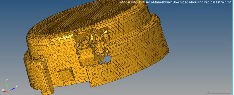
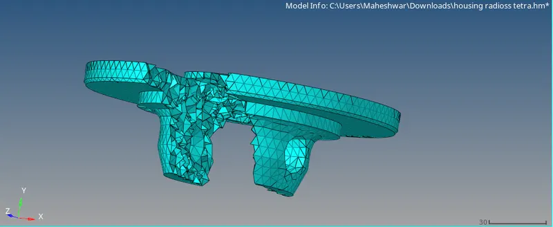
> Check for Tet Collapse ->
- After completing the Tetra Mesh, check for the failed element.
- Go to Tools > check elems (F10) > 3D > tet collapse (here 0.15).
- In the status bar, it will show how many failed elements are present in the model.
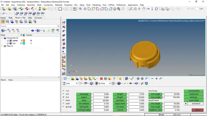
Hex mesh ->
> MESHING OF ARM BRACKET USING BRICK ELEMENTS.
PROCEDURE:
- Firstly, the arm bracket model was imported.
- The meshing of any component using Hexa elements is complicated as compared to the mesh using tetra elements. Generally, tetra mesh is widely preferred when the stresses generating on the component are not the part of concern and vice versa.
- In this assignment, the arm bracket has to be meshed using only brick elements. To do that, different methods had to follow for different sections of the arm bracket.
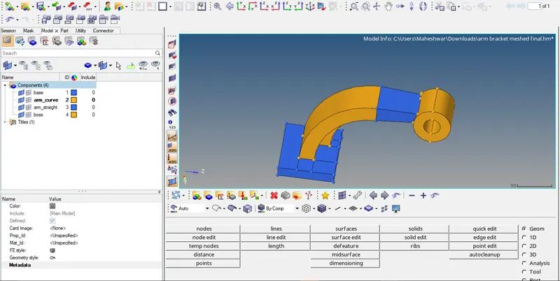
- From the figure, it can be observed that the arm bracket model consists of four different sections.
- While meshing using Hexa elements, manual inspection is required for nodal connectivity.
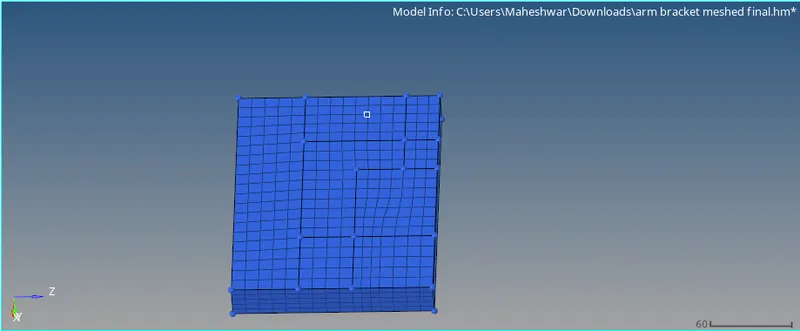
- Thus, each section had meshed individually. Firstly, the face of section 1 has meshed with 2D elements of size 10 units.
> ELEMENT OFFSET (SEC_1) ->
- Now, using 3D > Elem offset > solid layers, the 2D shell mesh is converted to 3d Hexa mesh with element thickness of 25 units and 5 layers,
- After the meshing of section 1, for the meshing of section 2, the different methods had to follow because of its curved shape.
- To mesh section 2, firstly, a centre of the curve is obtained for reference. It can be obtained using Geom > nodes > Arc Center, or Geom > distance > three nodes.
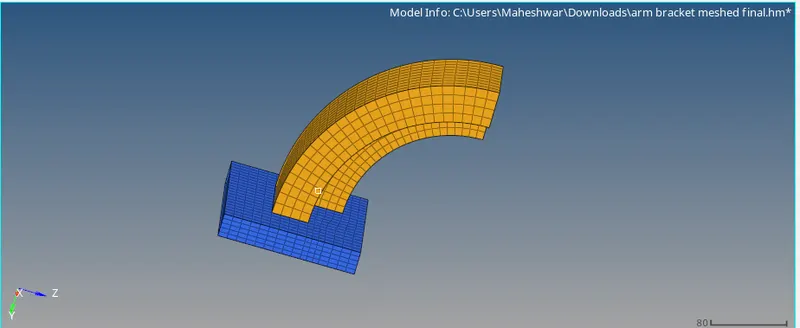
- The spinning of shell m along the x-axis for 90º to create 3D Hexa mesh on the curved section.
- Once section 2 is ready with 3D Hexa mesh, for meshing of section 3, which is a tapered section, the shell mesh of section 2 is required.
> LINEAR SOLID (SEC_3) ->
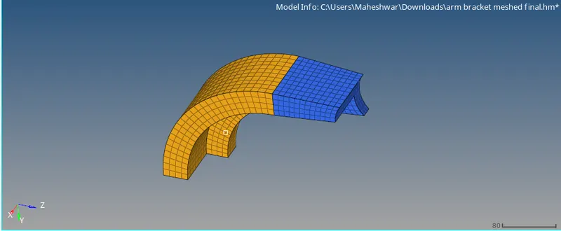
- Now, go to 3D > linear solid.
- From elements and to elements can be selected as the two end faces elements respectively. The alignment node should be exactly same on both the faces.
- Density can be set 12 > solids.
SOLID MAP (SEC_4) ->
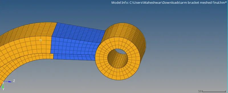
- The next component to mesh is the boss (sec-4). The option used for generating the mesh for this component is "Solid map".
- Initially, one side surface has meshed with 2D quad elements.
- The same number of nodes should be there at both ends. In order to have the quad elements.
Final view ->
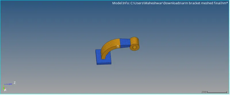
Conclusions:
- Generated a 3D mesh (using tetra and Hexa elements) on the given models. By following the given quality criteria.
Learning outcomes:
By doing this challenge, the following concepts can be understood ->
- Some calculations such as speed of sound, time step, T frequency values.
- Types of files in radios like starter & Engine files.
- Editing of engine file.
- 1D connectors deployment.
- 3D meshing using tetra & Hexa elements.