Assignment 2-RADIOSS Engine File Editing & 3D Meshing Challenge
- Check the material properties of the rail component and calculate the speed of sound in steel rail:
After Opening the “FIRST_RUN_0000.rad” file in Notepad to get the Material Property Data to calculate the Speed Of Sound In Steel rail, it was observed that the material Property are as follows:
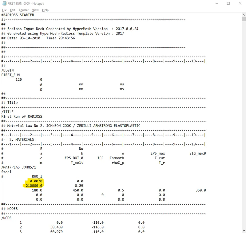
Fig.1 FIRST_RUN_0000.rad file
Density, ρ= 0.0078
Young’s Modulus, E = 210000
Speed Of Sound, C =`sqrt (E/rho)`=`sqrt (210000/0.0078)`= 5188.745217 m/s.
The Speed of Sound in Steel Rail = 5188.745217 m/s.
- Calculate the time takes for a shock wave to travel from one end of the rail to the other:
Given: Length of the rail = 1000 mm.
Formula: Time (Δt) = Length of the Rail (L)/ Speed of the Sound (C)
Time (Δt) = 1000/5188.745217 = 0.1927248223 ms.
- Time for sound to travel the length of the rail = 0.1927248223 ms.
- Edit the engine file so that the stress wave can be monitored, moving from one end of the rail to the other during an impact -this will require a termination time equal to the time it takes for the sound to travel the length of the rail(set on/RUN card).
Open the “FIRST_RUN_0001.rad” file in Notepad.
Edit the value of Time for sound to travel the length of the rail in the run card.
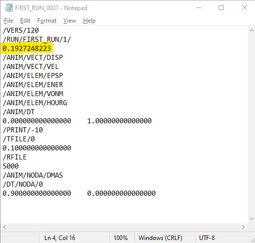
Fig.2 Edited Run Card for Δt.
- Set the frequency of animation output to a time that will give 20 animation steps(/ANIM/DT).
Formula: Time-frequency = Termination time (Δt) / Number of animation steps.
Time-frequency = 0.1927248223/20 = 0.009636241115
Open the “FIRST_RUN_0001.rad” file in Notepad and edit the same.
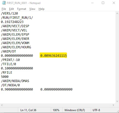
Fig.3 Frequency of animation output set.
- Change /print -10.
Open the “FIRST_RUN_0001.rad” file in Notepad and edit the same.
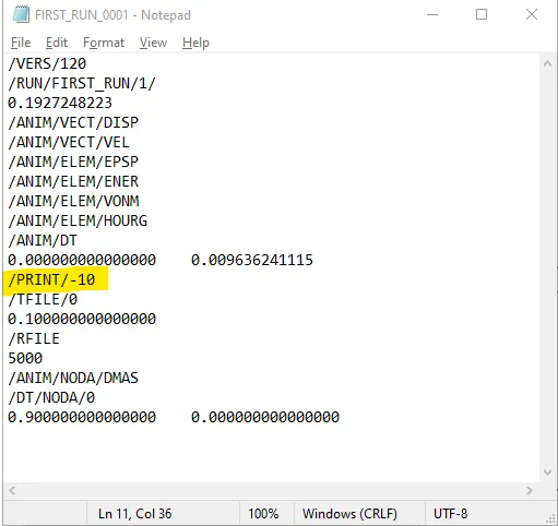
Fig.4 Edited FIRST_RUN_0001.rad file.
- 3D Meshing - Tetra Mesh And Hex Mesh - Report
1D ELEMENT – REPORT:
Import Geometry Clean-up:
The 1D Element Model was imported to the HyperMesh IMPORT MODEL option under the IMPORT tab. Then Surface was created from the Red Lines using the RULED option from the SURFACE menu of the GEOMETRY tab.
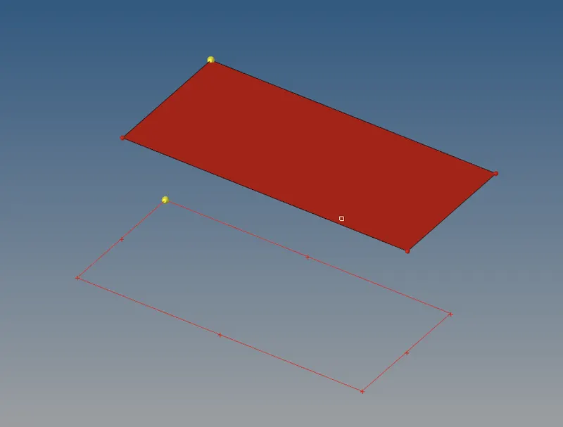
Fig.5 1D MODEL
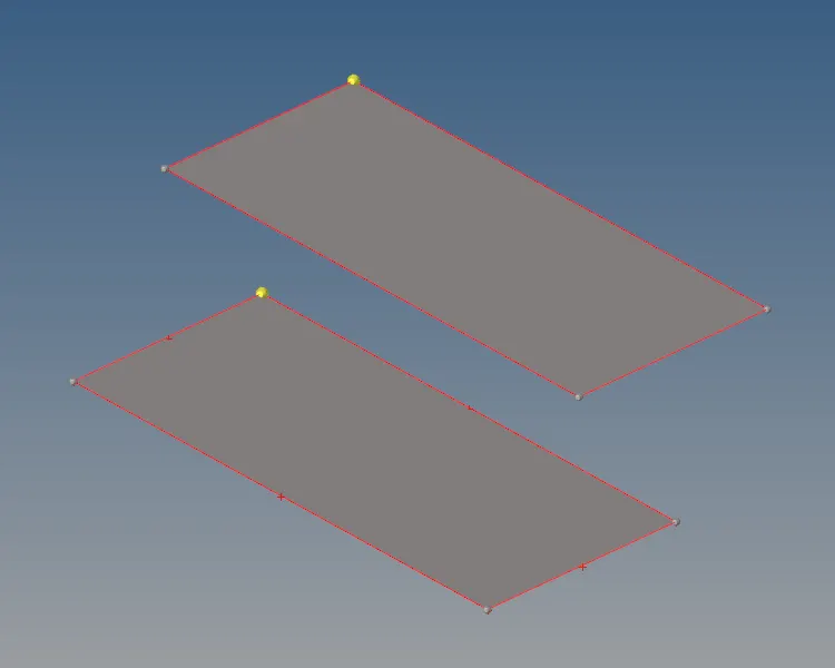
Fig.6 Surface created using the Ruled option.
Meshing:
Then 2D Meshing was carried out using the AUTOMESH option with a target element length of 3.5mm.
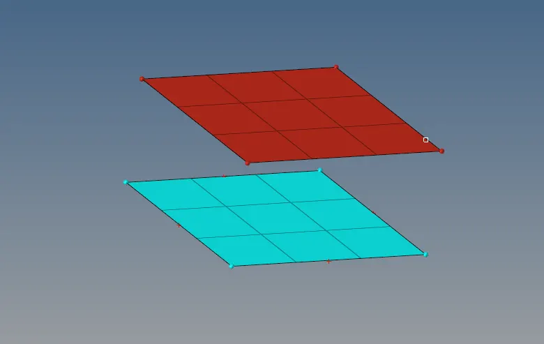
Fig.7 Mesh Generated.
1D Element creation:
Later 1D elements were created using the Bar, Spring, and Rigid options available from the 1D menu by selecting their type and nodes to connect them.
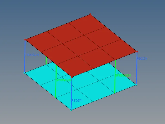
Fig.8 1D Element Created.
HOUSING TETRAMESH – REPORT:
Import Geometry:
The Housing Model was imported to the HyperMesh IMPORT MODEL option under the IMPORT tab.
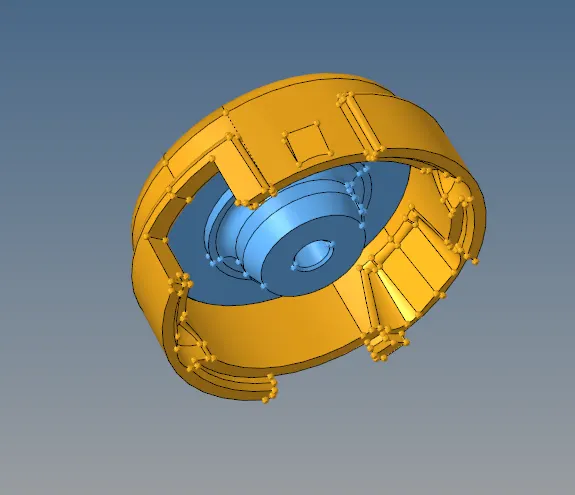
Fig.9 Housing Model.
2D Meshing:
Then 2D Meshing was carried out using the AUTOMESH option with a target element length of 5mm for the Housing Cover and Hub.
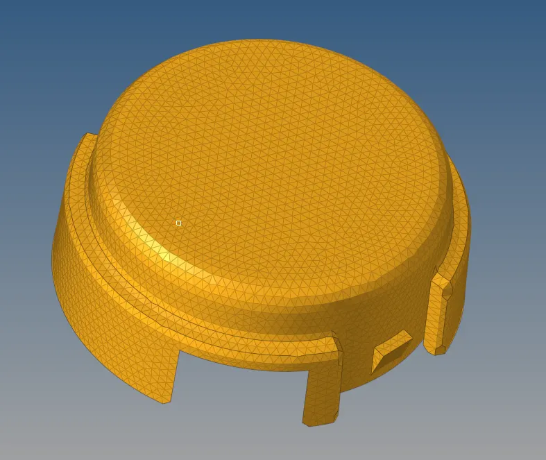
Fig.10 Housing Cover 2D Mesh.
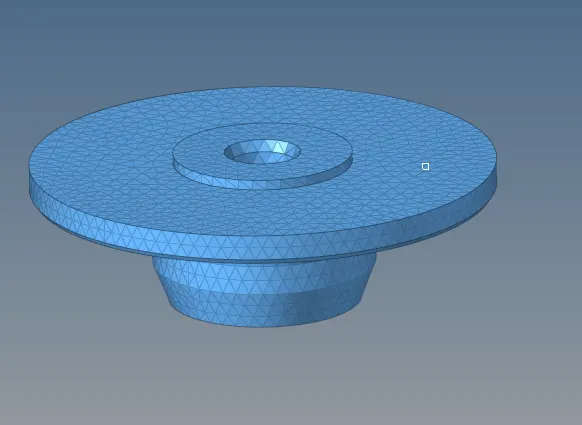
Fig.11 Housing Hub 2D Mesh.
3D Meshing:
Then 3D Meshing was carried out using the TETRAMESH option from the 3D menu bar with a TET COLLAPSE of 0.15 for the Housing Cover and Hub. If any quality issues in the tet collapse were then cleared using Fix 3D elements from the TETRAMESH tab.
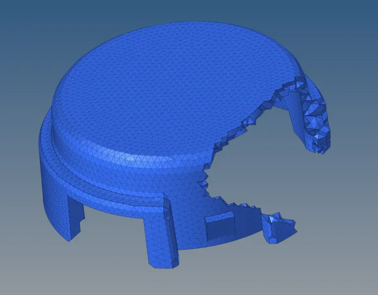
Fig.12 Housing Cover 3D Mesh.
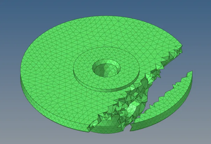
Fig.13 Housing Hub 3D Mesh.
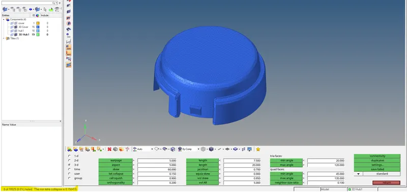
Fig.14 Tet Collapse Quality cleared.
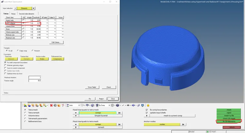
Fig.15 Fix 3D Elements option.
ARM BRACKET HEXAMESH – REPORT:
Import Geometry:
The Arm Bracket Model was imported to the HyperMesh IMPORT MODEL option under the IMPORT tab.
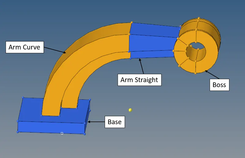
Fig.16 Arm Bracket Model.
BASE Meshing:
Then 2D Meshing was carried out using the AUTOMESH option with a target element length of 10mm QUADS ONLY. It was ensured that no trias are present on the Base Surface
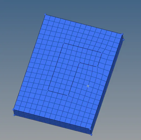
Fig.17 Base 2D Mesh.
Then the 2D Mesh was converted to 3D Mesh using the LINE DRAG – DRAG ELEMS option from the 3D menu tab. First, the ELEMENTS needed to be dragged were selected followed by selecting the LINE and then DRAG.
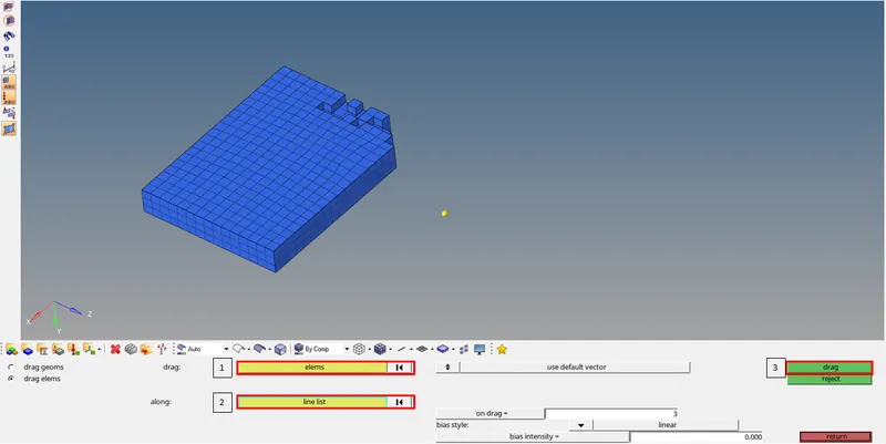
Fig.18 Base 3D mesh
ARM CURVE Meshing:
Then the 3D Mesh was generated on the arm curve using the SPIN – SPIN ELEMS option from the 3D menu tab. First, the ELEMENTS were selected followed by selecting the BASE POINT for the rotation and Rotation about X-axis, then ANGLE OF ROTATION = 90, ON SPIN = 25, and then SPIN-.
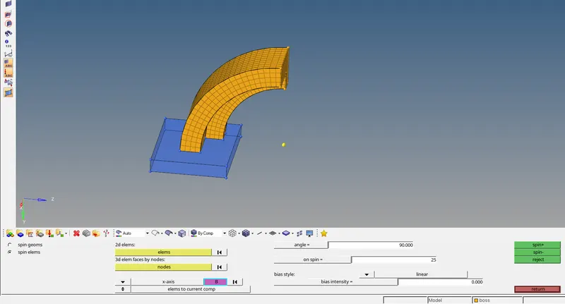
Fig.19 Arm Curve 3D mesh
ARM STRAIGHT Meshing:
Then the 3D Mesh was generated on the arm straight using the LINEAR SOLID option from the 3D menu tab. First, the TOOLS – FACES – FIND FACES option was used to create a 2D Mesh on the Arm Curve End. The 2D mesh was generated on the Arm Straight End connected to the Boss with the same number of elements and nodes. Later LINEAR SOLID option was used by selecting FROM ELEMS and TO ELEMS along with their Alignments with a Density of 12.
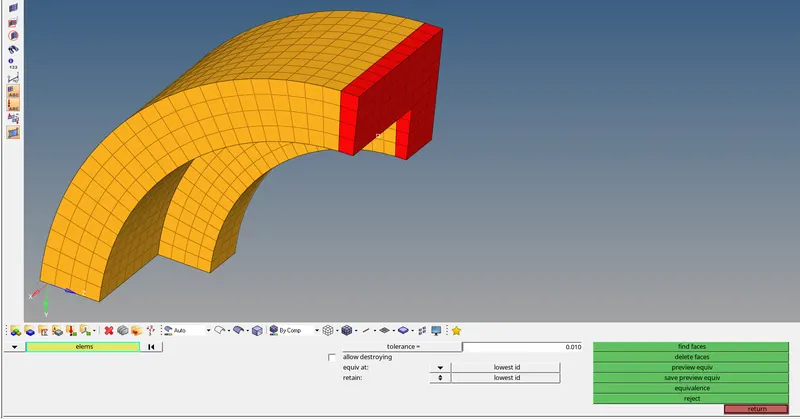
Fig.20 Arm Curve Find Faces.
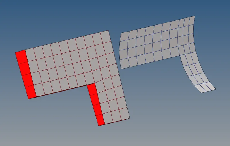
Fig.21 Arm Straight 2D Mesh
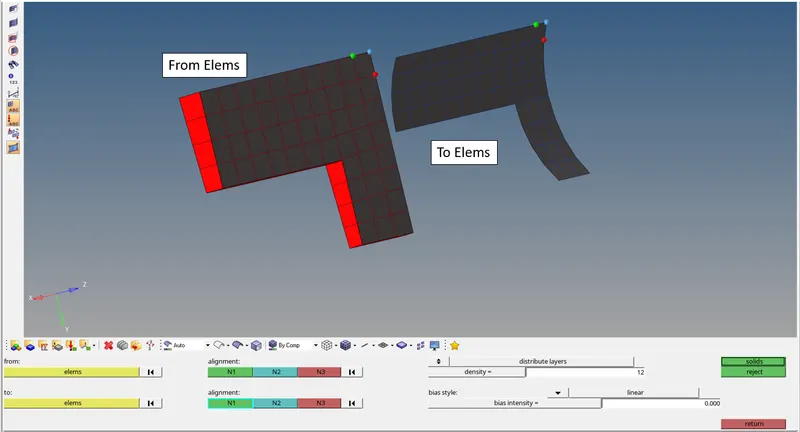
Fig.22 Linear Solid option
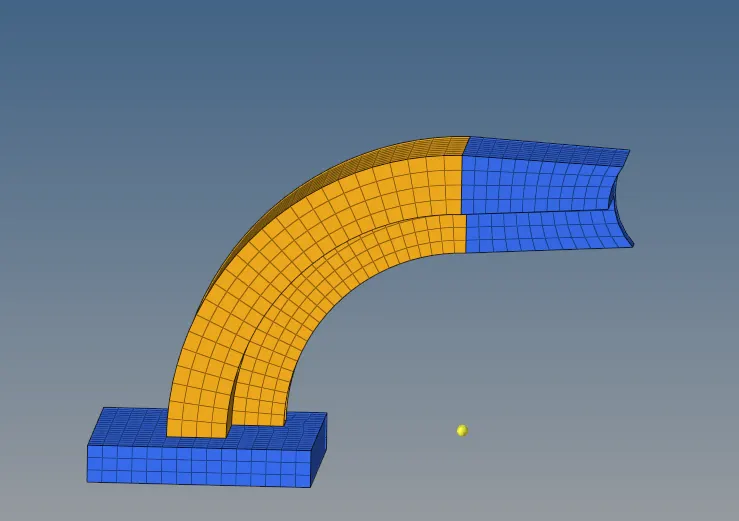
Fig.23 Arm Straight 3D Mesh
BOSS Meshing:
Then 2D Meshing was carried out using the AUTOMESH option with a target element length of 10mm QUADS ONLY. It was ensured that BOSS Surface elements matches the 3D Elements of the Previous part.
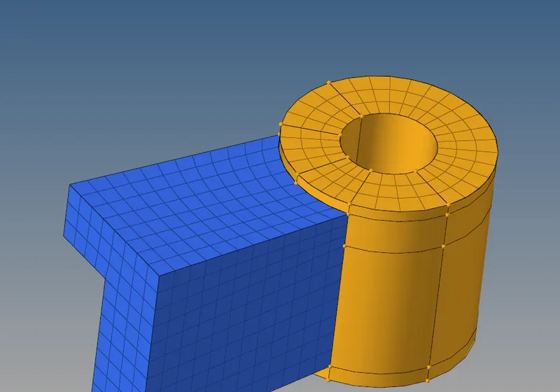
Fig.24 Boss 2D Mesh.
Then the 3D Mesh was Generated using the SOLID MAP – GENERAL option from the 3D menu tab. First, the ELEMENTS needed to be dragged were selected followed by selecting the Source and Destination Geometry which are the Upper Circular part and Lower Circular Part of the Boss, followed by providing Along Node Path and then MESH.
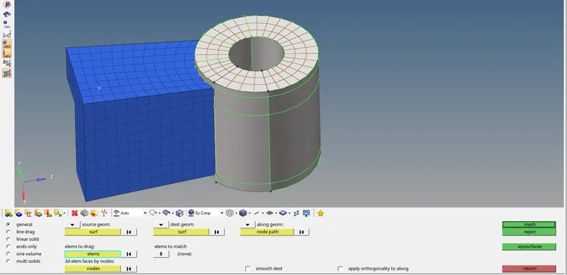
Fig.25 Boss Solid Map
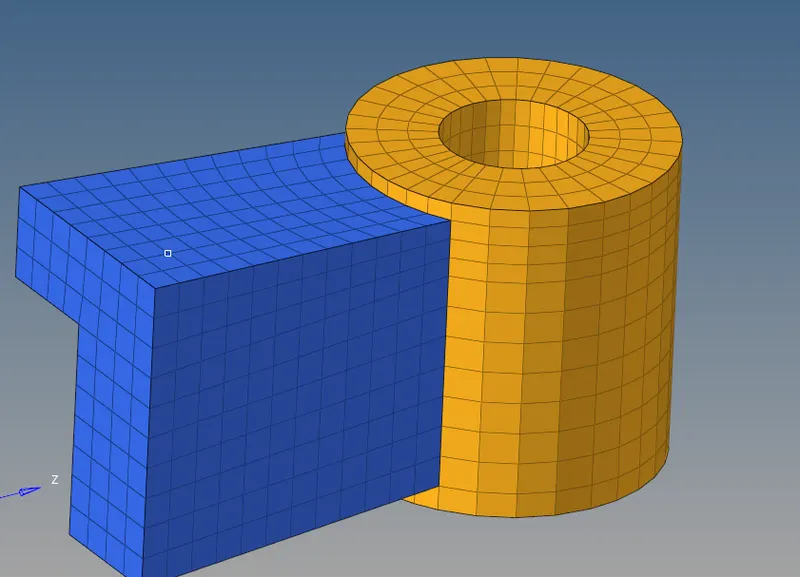
Fig.26 Boss 3D mesh
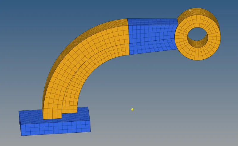
Fig.27 Final Mesh Model