Assignment 2-RADIOSS Engine File Editing & 3D Meshing Challenge
Questions:
1. Check the material properties of the rail component and calculate the speed of sound in steel rail=_______
2. The length of the rail is about 1000 mm.calculate the time takes for a shock wave to travel from one end of the rail to the other.
3.Time for sound to travel length of rail=______
4.Edit the engine file so that the stress wave can be monitored, moving from one end of the rail to the other during impact -this will require a termination time equal to the time it takes for the sound to travel the length of the rail(set on/RUN card)
5.Set the frequency of animation output to a time that will give 20 animation steps(/ANIM/DT)
6.Change /print -10.
7.3d meshing tetra mesh and hex mesh
- Repeat class examples and, maintain the quality.
- Target tet size=5mm,hex size=10mm,tet collapse=0.15.
SOLUTIONS:
1. Check the material properties of the rail component and calculate the speed of sound in steel rail=_______
- First of all, we will open the material property to check the steel properties. So, for that we have to follow some steps.
Go to File > Solver Deck > File Type RADIOSS and provide file path > Import
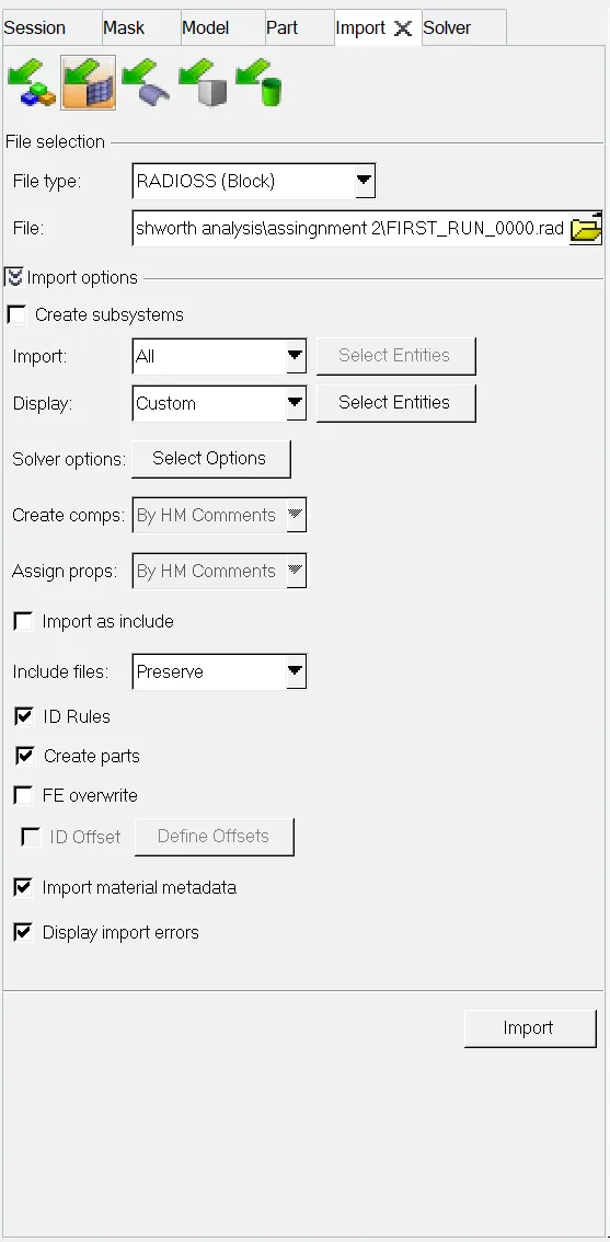
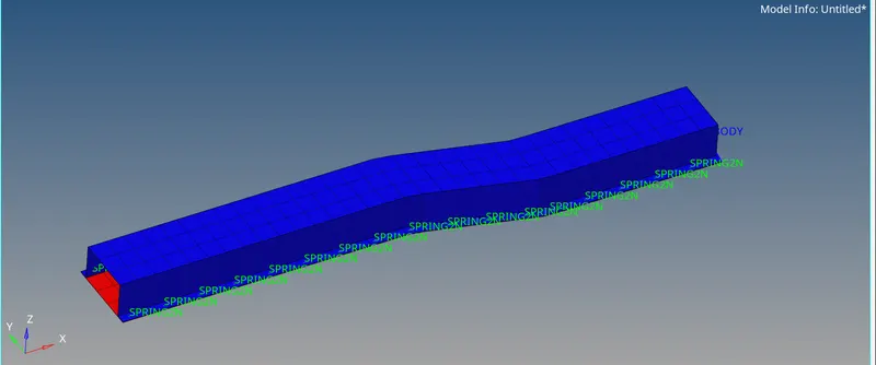
- Now file is imported “FIRST_RUN_0000.rad”, So to check the Material property of FURST_RUN_0000.rad we have to follow some steps.
Go to Model tree > Materials > Steel > And we can able to see the property
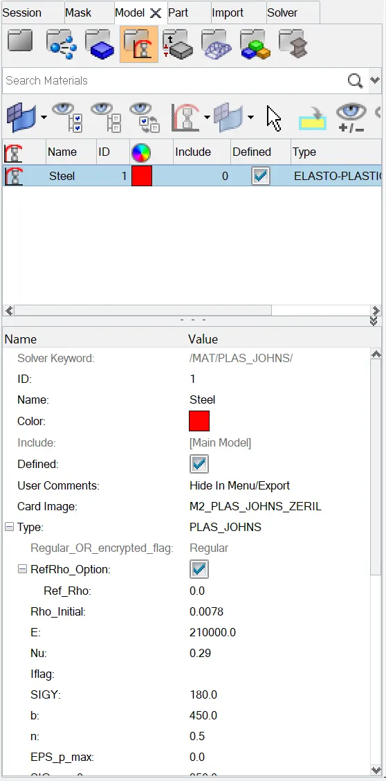
- As we can see that above figure is having Young’s modulus, Rho, and Poisson’s ratio. So now we will calculate the speed of sound in steel rail by using above data.
- Young’s modulus (E) N/mm2 = 210000
- Rho (ρ) Density Kg/mm3= 0.0078
- Poisson’s ratio = 0.29
Speed of sound', C= √E/ρ
C= √210000/0.0078
C= 5188.75 m/s
speed of sound in still rail is 5188.75 m/s
2. The length of the rail is about 1000 mm.calculate the time takes for a shock wave to travel from one end of the rail to the other.
Speed = Distance/Time
5188.75= 1000/ T
T= 0.1927ms
3. Time for sound to travel length of rail=0.1927ms.
4.Edit the engine file so that the stress wave can be monitored, moving from one end of the rail to the other during impact -this will require a termination time equal to the time it takes for the sound to travel the length of the rail(set on/RUN card)
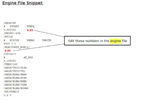
- For editing the engine file, we have to follow some steps.
Go to File > Import > Solver deck > Locate the .rad file > Import
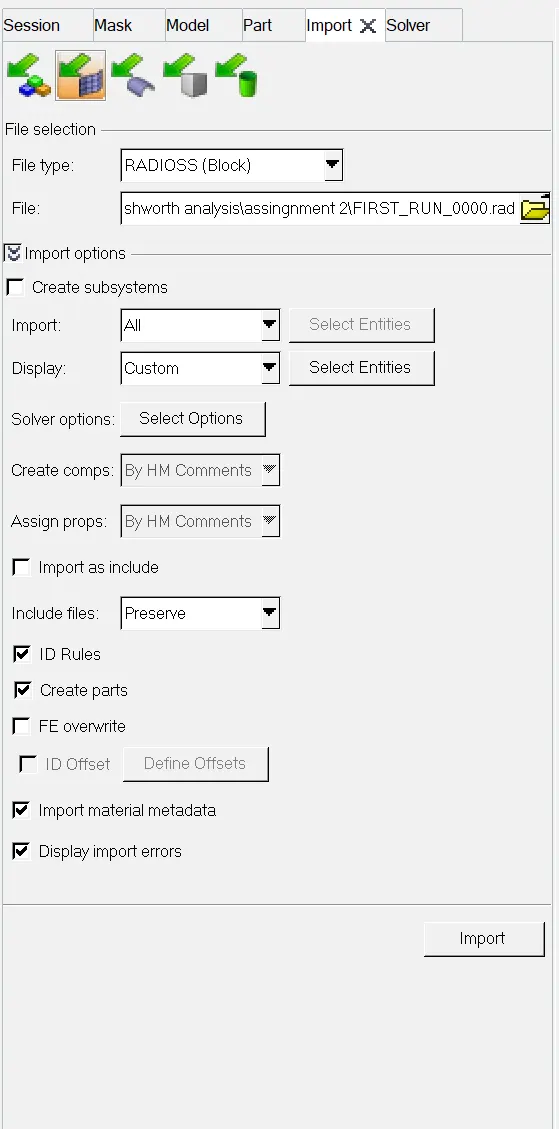
- Now file is imported and next step is to find engine file.
Go to Model tree > Cards > Engine RUN > Tstop > change the time.
- As we have already calculated the Time i.e., Ts = 0.1927 ms or 0.0001927 sec, now we have to add this time step in engine file.
- Replace Tstop = 60 to 0.1927
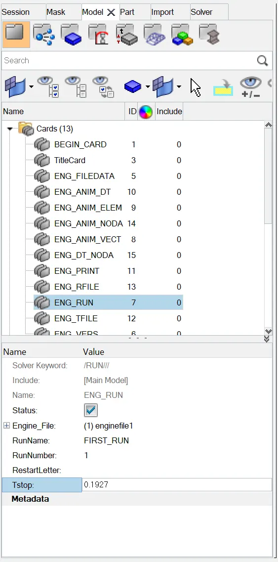
- Now another way to edit engine file is by following step.
Go to File > Export > solver deck > Check the box “Export Engine file only” > Now give location to save the file with proper name > Export.
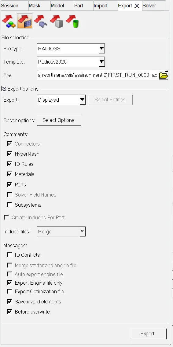
- Now go to exported file location and open file in notepad and replace 60.0 to 0.1927.
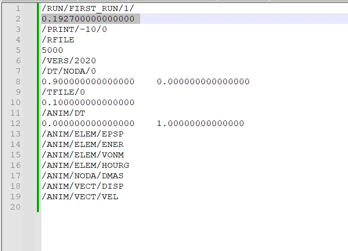
- Now save the file.
- If we are changing directly in Hypermesh Radioss then it will automatically be updated by second technique so we not require to use second method and if we are using second method then we not require to edit in hypermesh radioss.
5.Set the frequency of animation output to a time that will give 20 animation steps(/ANIM/DT)
- Now to set the frequency of animation output to a time then first we have to import the geometry in solver deck as we done before.
- First, we have to calculate the time related to frequency of animation.
As given,
Animation steps (As)= 20
Time Stop (Ts) = 0.1927 (Calculated before)
Time related to frequency of animation Tfreq = Ts / As
= 0.1927 / 20
Tfreq = 0.009635
- Now we will enter this value in time related to frequency of animation.
Go to model tree > Cards > ENG_ANIM_DT > Change the value Tfreq
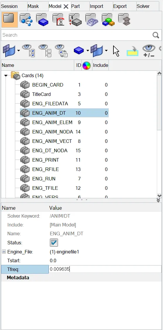
- We can also change the value by exporting the engine file and by using notepad.
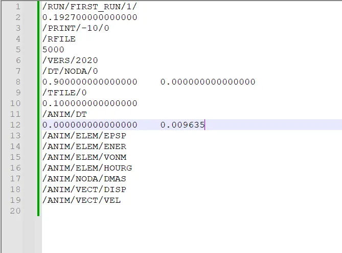
- Now we will check the animation depending upon Tstop and Tfreq.
Go to Analysis > Radioss :> Click on Radioss
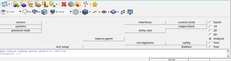
- Now give location to save the animation time steps and frequency.
Go to input file > assign proper name > save > click on Radioss.

- A simulation window will start showing the results.
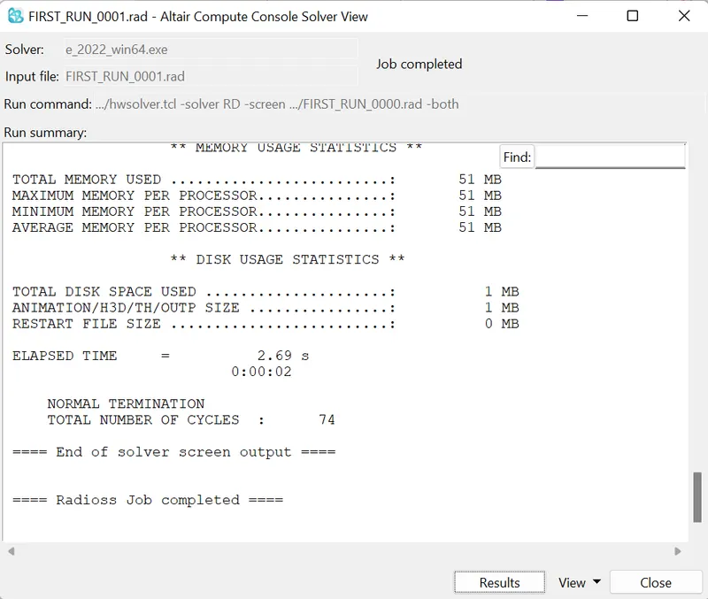
- Click on result to see the result output. A new window will open with result.
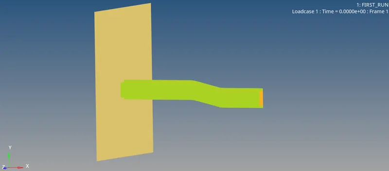
- Now go to file location of saved animation to check the number of animation frequency depending upon time stop.
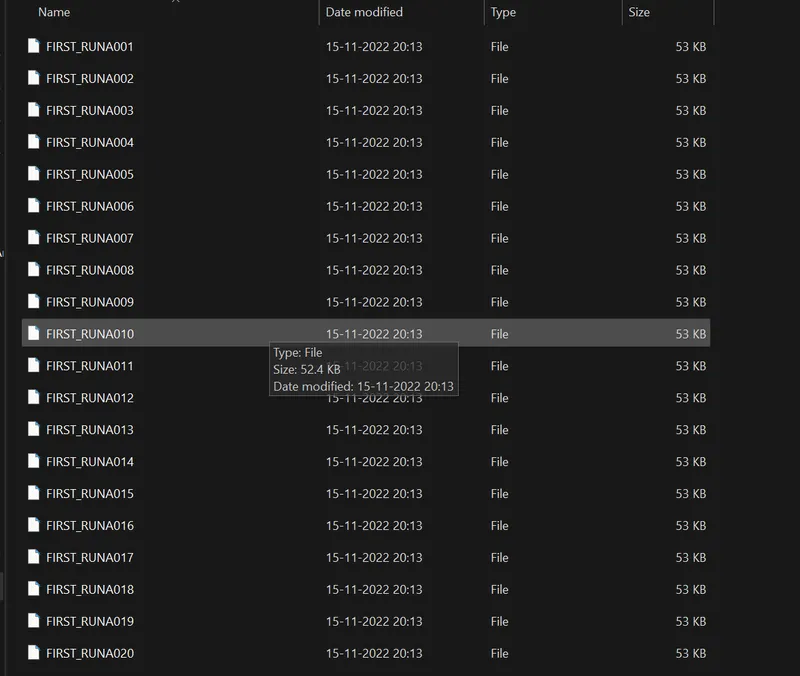
- As in above figure we can see the number of animation steps depending upon Tfreq = 0.009635
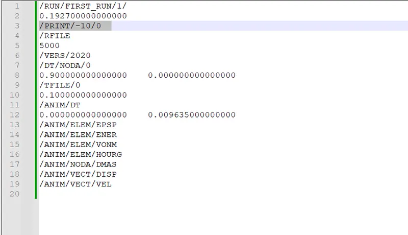
6.Change /print -10.
- To change the print
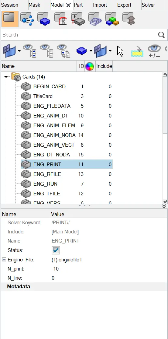
Go to Model tree > Cards > ENG_PRINT > N_print -10
- Also, we can change print number by exporting the engine file and editing in notepad.
Go to File > Export > solver deck > Give path to save > check on export engine file > Export.
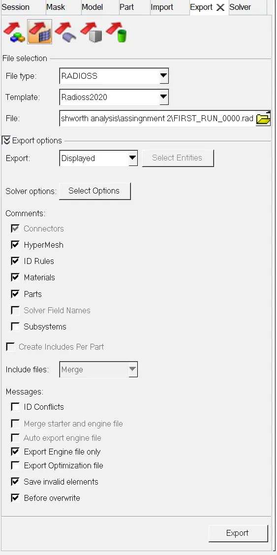
- Now change in notepad.
Go to exported file > open in notepad > Change PRINT
7.3d meshing tetra mesh and hex mesh
- Repeat class examples and, maintain the quality.
- Target tet size=5mm,hex size=10mm,tet collapse=0.15.
case1: housing
import geometry
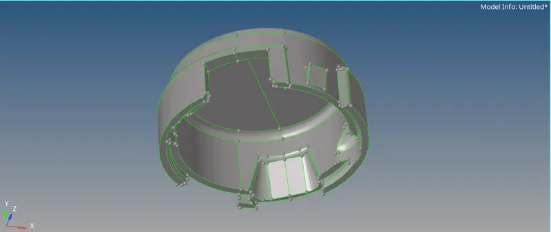
- Before that we will do automesh for 2D component Go To 2D > Automesh > element size 5 > mesh type Trias > mesh

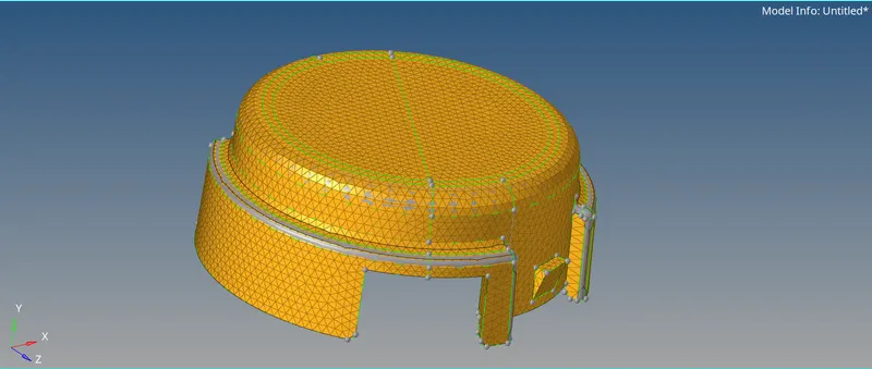
- For tetra meshing Go to 3D > Tetra mesh > Set parameter (Tetramesh parameters) > Set Tetra size = 5 > Tet Collapse = 0.15 > Tetra mesh > select all Elements > Create per-volume comps > Mesh
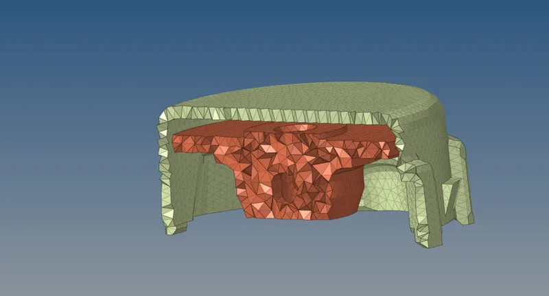
- Apply mask to see inner meshed area.
Go to tool > mask > Shift + mouse key and drag to select mesh area > Mask
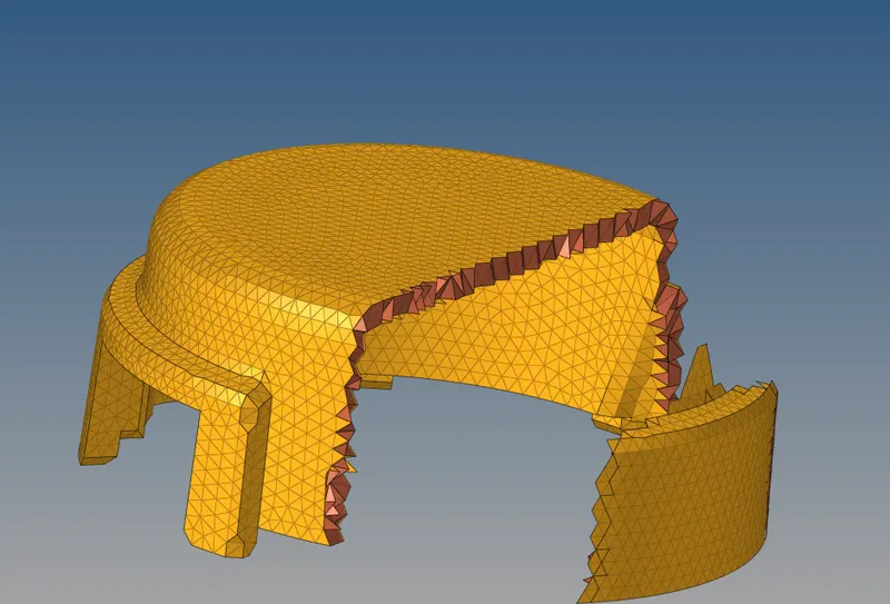
- Now to check the quality of mesh we go to check element
Go to tools > Check elems > 3D > Tet collapse > 0.15


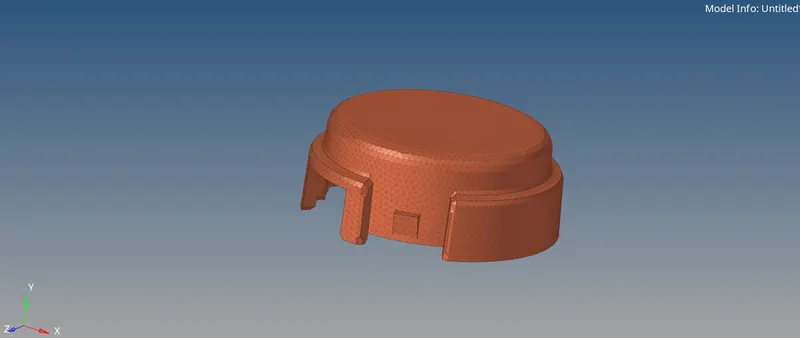
- Now next step is to do meshing of hub.
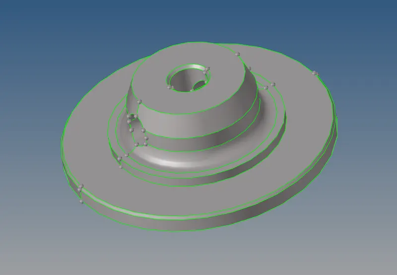
- Automesh for 2D component Go To 2D > Automesh > element size 5 > mesh type Trias > mesh
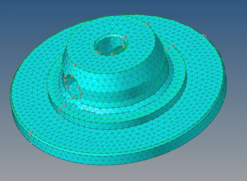
- For tetra meshing Go to 3D > Tetra mesh > Set parameter (Tetramesh parameters) > Set Tetra size = 5 > Tet Collapse = 0.15 > Tetra mesh > select all Elements > Create oer-volume comps > Mesh
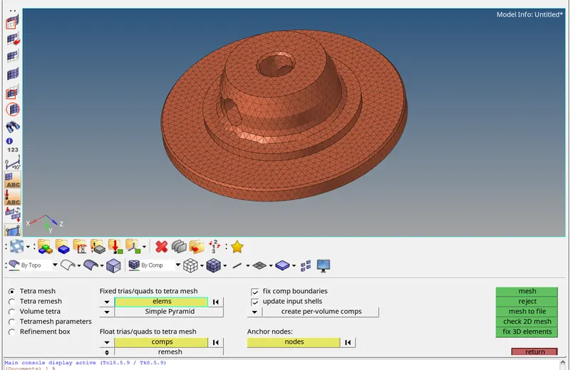
- Now to check the quality of mesh we go to check element
Go to tools > Check elems > 3D > Tet collapse > 0.15
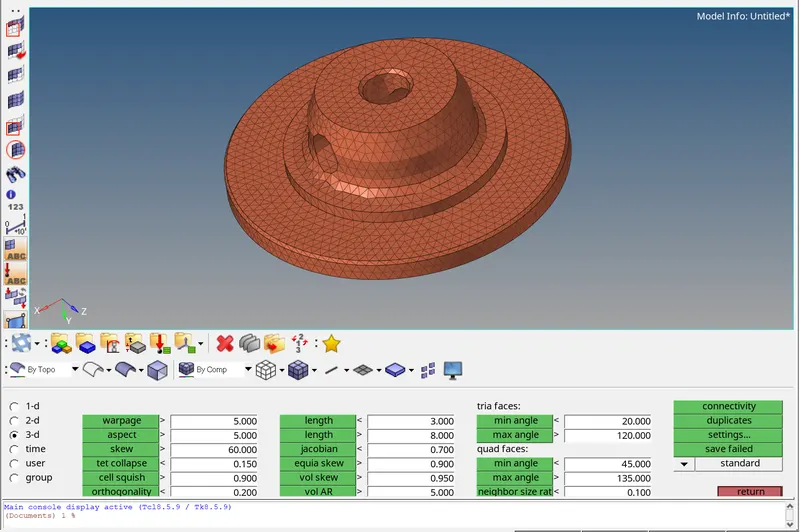

tetra mesh:
Arm Bracket Meshing – Hex Mesh
- First, step is to import the model
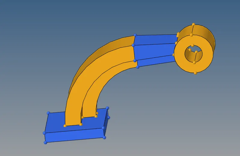
- Here we will perform individual meshing for each component, so first we will mesh base and hide all othe components.
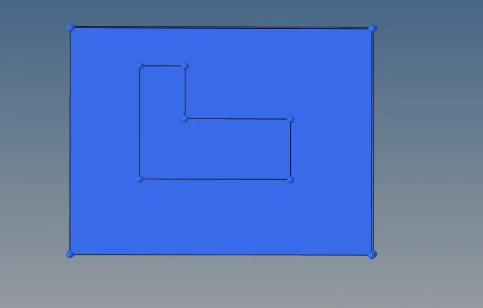
- For the meshing
Go to 2D > Automesh > element size = 10 > mesh type Mixed > select top surface > mesh
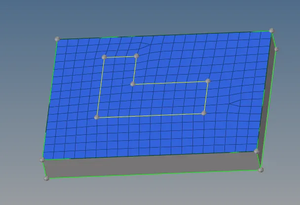
- Now to remove the tries Go to Quality index > Cleanup tool > drag trias element > outside the mesh.
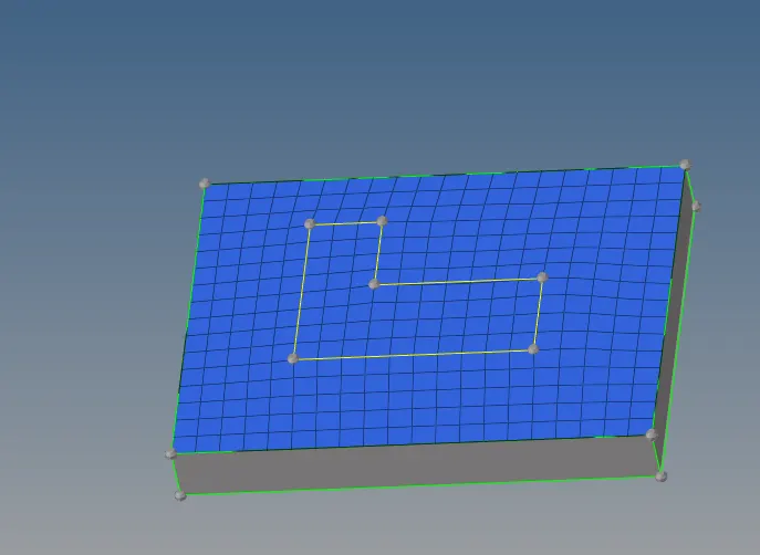
- Now go to element cleanup > select the highlited element > cleanup
- Now we have a better mesh.
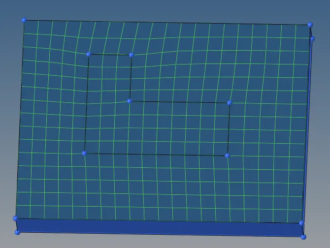
- Applying 3D meshing on same
Go to 3D > elem offset > Select the meshed element > along geom to follow (Select two surface) > Numbers of layer 5 > total thickness 25 ( To check the thickness click F4 and define with two points & Return) > Offset +

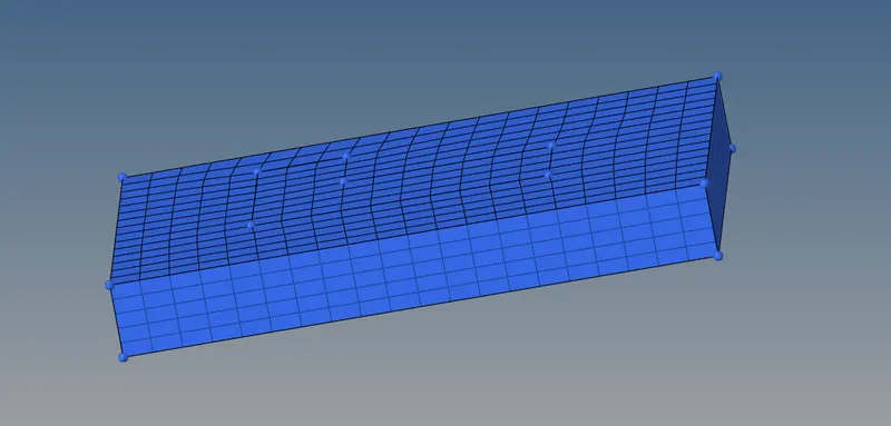
- Now meshing the arm curve so, unhide the component.
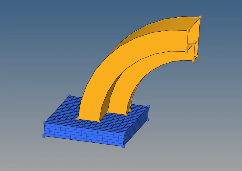
- Now hide the 3D element in base
Go to model tree > component > Base > click on 3D icon to hide
- Now by pressing F5 in mask and click on elems and select by config.
Go to Elems > by config > config = hex8 > select entities.
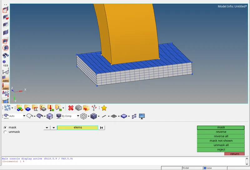
After selecting the entities, Mask them and we will get 2D element
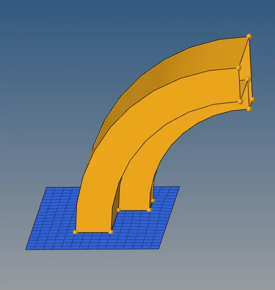
- Now by using spin feature we will create other meshing.
Go to 3D > Spin > Spin element > angle = 90 > On spin = 25 (estimate) > Plane definition = X axis (x-axis is selected to the plan with rotational point)
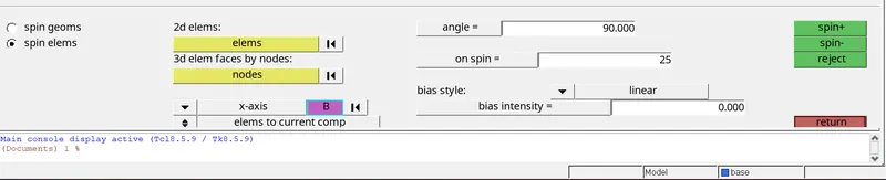
- After setting the above value now press F4 to create centre point of circle and drag cursor to surface line and create 3 points. After that click circle center. As we can see in bellow figure with three-point node and center circle point.

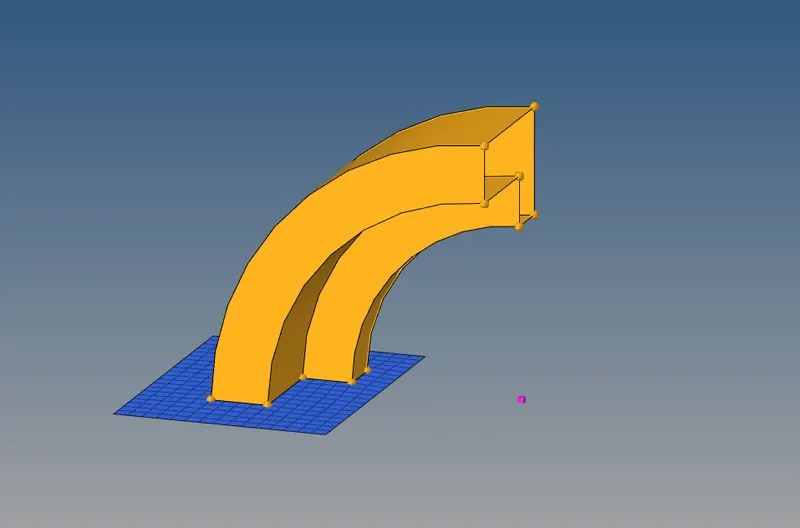
- Now go back to spin command and select the center point and click on spin (-) to create mesh.
- Select all element and spin (-)
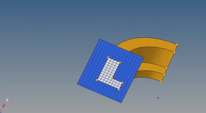
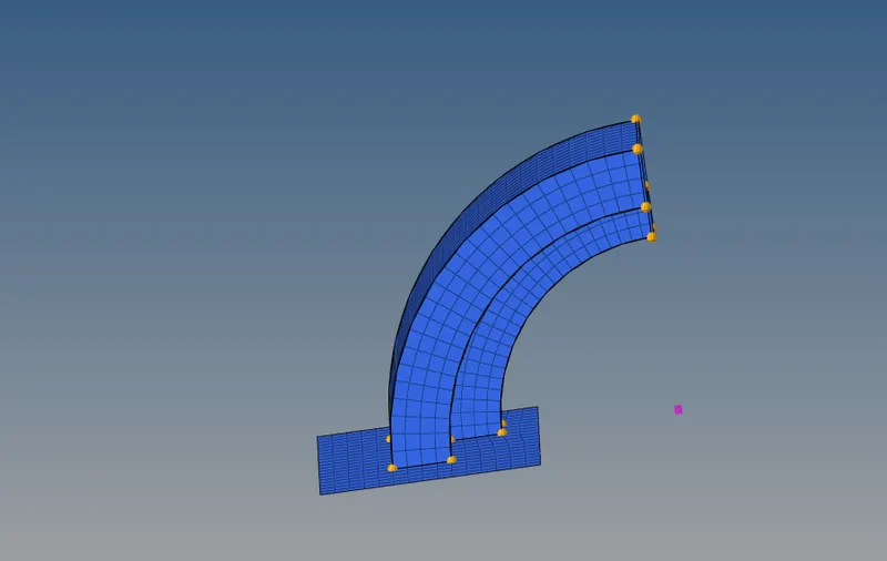
- Now we have to mesh other two component i.e. arm straight and boss by using linear solid.
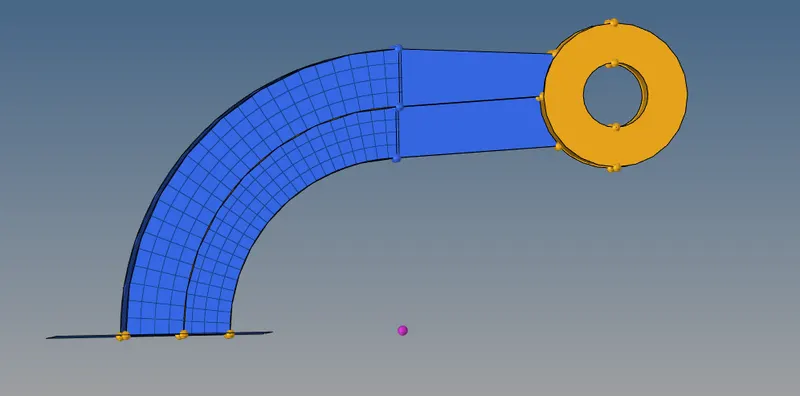
- Before that we need faces.
Go to Tool > faces > comps > arm curve > select
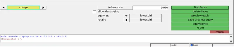
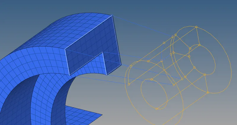
- As we can see that face is highlighted, now we will hide components which are not require.
Go to 3D > linear solid > select from element and to element > alignment with node equal on both side > density 12 ( half of arm curve > solids
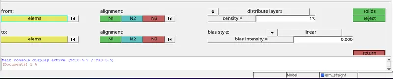
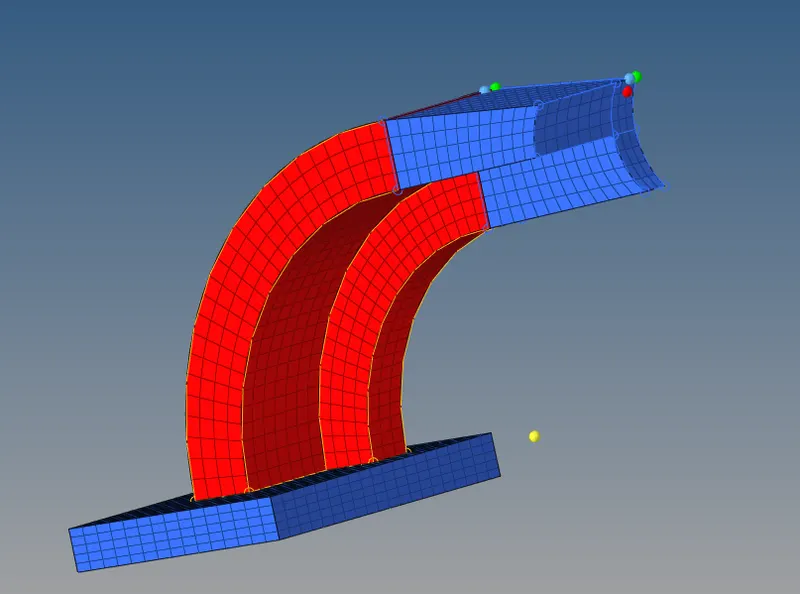
- In above figure we can see that the mesh is generated by using linear solid method.
- Now delete the faces
Go to tools > Faces > Delete faces.
- Next thing is to mesh the boss.
Go to 2D > Automesh > select all faces of boss > mesh
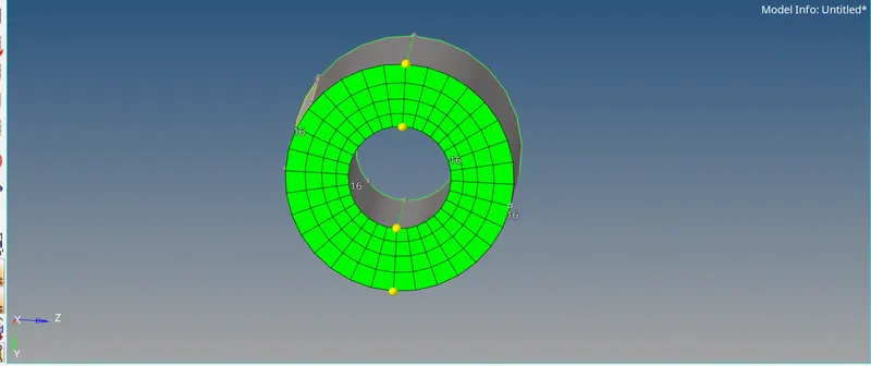
- Now we get the perfect matched mesh.
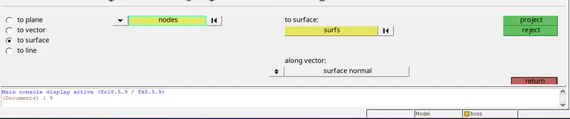
- Now by using project we will mesh all the boss component. Go to tool > project > to surface > select node ( of arm straight) > node > duplicate > select boss surface > project
- Click on along vector and select surface normal > click on surfs > nodes > project. Once we will project it will create temporary node.
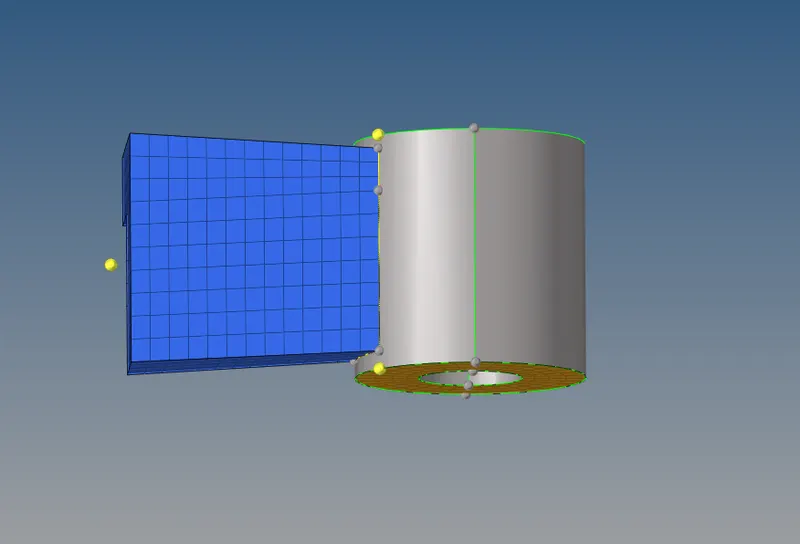
- Now next step is to create solid map.
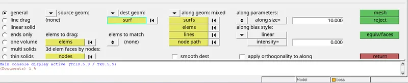
Go to 3D > solid map > source geom (None) > dest geom (select surface which having temp node) > elems to drag (select another meshed elements) > along geom (mixed) > node path ( select all the node path) > select line > mesh

Final meshed:
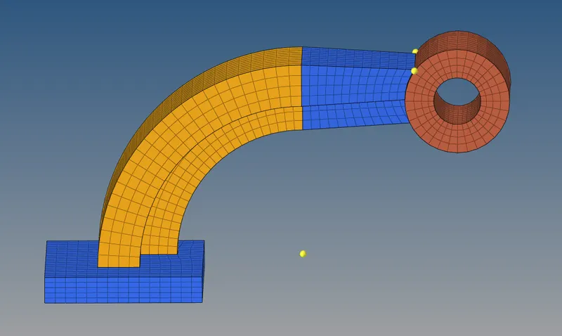
Conclusion:
All the questions are answers, 3d mesh are created on given 2 cases.