Assignment 2-RADIOSS Engine File Editing & 3D Meshing Challenge
Crashworthiness Analysis using HyperMesh and Radioss
#Assignment 2 - RADIOSS Engine File Editing & 3D Meshing Challenge
AIM: Engine File Calculation, Editing & 3D Meshing
OBJECTIVES:
(1). To calculate parameters from given Engine input file.
- Checking the material properties of the rail component and calculating the speed of sound in steel rail.
- Calculating the time it takes for a shock wave to travel from one end of the rail to the other if the length of the rail is 1000 mm.
- Calculating time for sound to travel length of rail
(2). To edit Engine output file.
- Editing the engine file so that the stress wave can be monitored, moving from one end of the rail to the other during impact -this will require a termination time equal to the time it takes for the sound to travel the length of the rail(setting on RUN card)
- Setting the frequency of animation output to a time that will give 20 animation steps(/ANIM/DT)
- Changing /print -10.
(3). To connect 1-D different collectors to given geometry.

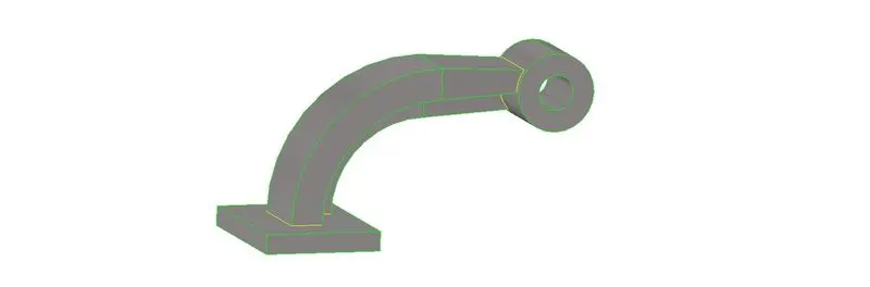
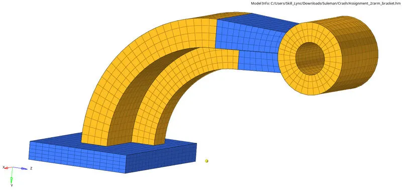
(4). 3D Mesh of arm bracket.
- Hex size=10mm
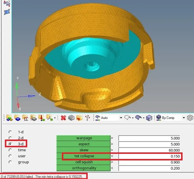
(5). 3D Mesh of Housing components.
- Target tet size = 5 mm
- Tet collapse = 0.15

PROCEDURE FOR OBJECTIVE 1 :
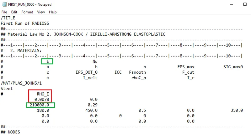
(1). Check the material properties of the rail component and calculate the speed of sound in steel rail=_______
Solution 1:
Given --
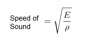
We know that --
Calculation --
Speed of Sound = (Modulus/Density)^½ [Under root can be represented as ^½ ]
Speed of Sound = (210000/0.0078)^½ [From given data]
Speed of Sound = (210000)^½ / (78/10000)^½ [converting decimal to simple form]
Speed of Sound = (21/78)^½ *100*100
Speed of Sound = 0.5188745*100*100
Speed of Sound = 5188.745 m/s [Equation (I)]
(2).The length of the rail is about 1000 mm.calculate the time it takes for a shock wave to travel from one end of the rail to the other.
Solution 2 :
Given -- Length of the rail = 1000 mm.
We know that--
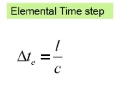
Elemental Time Step = Length of Element / Speed of Sound
Calculations --
Elemental Time Step = 1000 mm / 5188.745 m/s [from given data & equation (I) respt. ]
Elemental Time Step = 1 m / 5188.745 m/s [converting mm to m]
Elemental Time Step = 0.0001927 s --- i.e. 0.1927 ms [ Equation (II) ]
(3). Time for sound to travel length of rail=______
Answer 3: Time for sound to travel of rail is the same as shock wave travel in rail.
That is 0.1927 ms [From equation (II) ]
PROCEDURE FOR OBJECTIVE 2 :
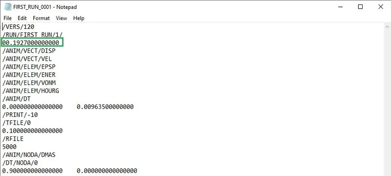
(4). Edit the engine file so that the stress wave can be monitored, moving from one end of the rail to the other during impact -this will require a termination time equal to the time it takes for the sound to travel the length of the rail(set on/RUN card)
Answer 4: From equation (II), We can show that --
(5). Set the frequency of animation output to a time that will give 20 animation steps(/ANIM/DT)
Solution 5 :
Given -- No. of animation steps = 20
We know that--
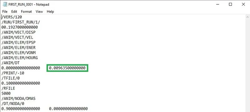
Tfrequency = Time of sound travel / Number of animation steps
Calculation --
Tfrequency = 0.1927 / 20 [From equation (II) and given data respt.]
Tfrequency = 0.009635 Hz
We can show that as --
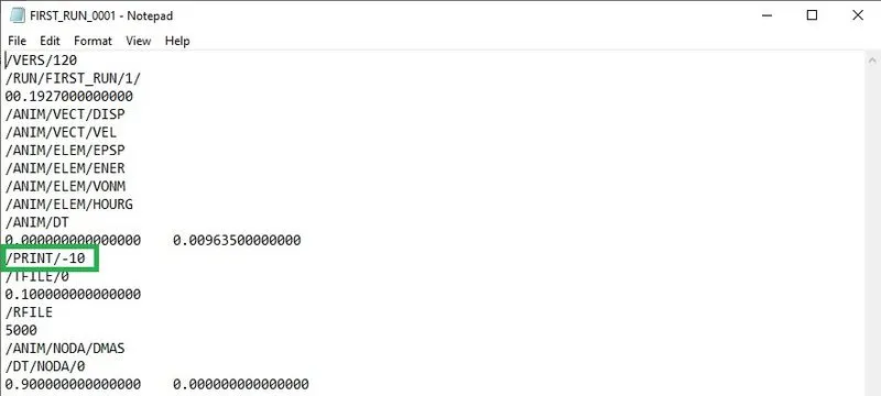
(6). Change /print -10
Answer 6 : We can show that as --
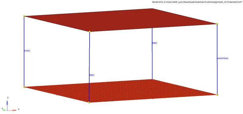
PROCEDURE FOR OBJECTIVE 3 : To connect 1-D different collectors to given geometry.
STEP 1: Creating temporary nodes at all four corners of the geometry
*Geom>Temp nodes>select all four corners>add
STEP 2: Obtaining RBE2 rigid element at one of the corner of the geometry.
*1D>rigids>create>select independent node>select dependent node>element type(RBE2)>create

STEP 3 : Obtaining spring element at second corner of the geometry.
*1D>springs>create>select first node >select second node>element type(HMSPRING)

STEP 4 : Obtaining RBE3 element at third corner of the geometry.
*1D>rbe3>create>select independent node>select dependent node>element type(RBE3)>create

STEP 5 : Obtaining rod element at fourth corner of the geometry.
*1D>rod>create>select first node >select second node>element type(CROD)
PROCEDURE FOR OBJECTIVE 4 : 3D Mesh of arm bracket with hex size of 10mm.
STEP 1: 2D mesh on Base component with 10mm element length.
*2D>automesh>surface>select surface>mesh
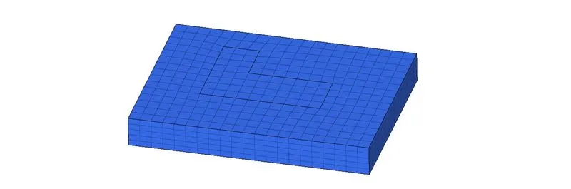
STEP 2: 3D element offset of 2D elements of base component
*3D>offset elements>solid layers>select 2D elements>select along surface>number of layers(5)>total thickness(25)>offset +

STEP 3: Mask hex 8 elements by configuration so that only 2d elements can we shown, which will help us to 3D mesh arm curve component
*F5>elements>by config>hex 8>select entities
STEP 4: Create a center node of arm curve component, which will help us to spin the elements.
*F4>three nodes>select line>put node N1,N2,N3>circle center
STEP 5: Spin panel can be used to spin the 2D elements of base component to arm curve component.
*3D>spin>spin elements>select 2D elements>select axis of rotation(x-axis)>select base node>angle(90 degree)>on spin(25)>spin -
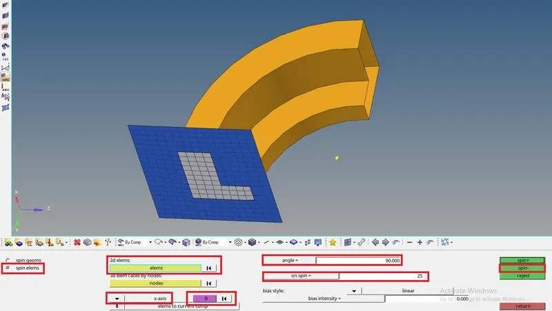
STEP 6 : 2D mesh on the front side surface of the arm straight
NOTE: The number elements on the arm straight should be equal to the number of elements of last face of arm curve.
STEP 7: Find faces of the arm curve
*Tool>faces>select arm curve component>find faces
STEP 8: 3D linear solids panel can be used to create 3D elements in arm straight as followed--
*3D>linear solids>from elements>select elements of first surface by face>select alignments nodes N1,N2,N3>select elements of second surface by face>select alignments nodes N1,N2,N3>density(12)>solids
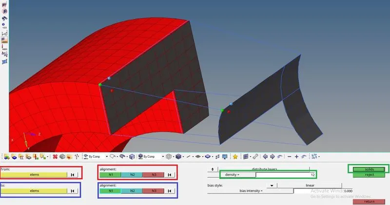
STEP 9: Create 2D mesh on one side of circular upper part of the boss component.Keep equal number of elements outer and inner side of the surface.
STEP 10: Duplicate node to below side of the surface of boss
*Tool>Project>to surface>node>select node>duplicate>select surface>project
STEP 11: To create 3D elements in Boss component , we can go through solid map panel
*3D>solid map>general>select elements by face>select destination surface>along geom>mixed>select node path>select line>along parameters size(12)>mesh
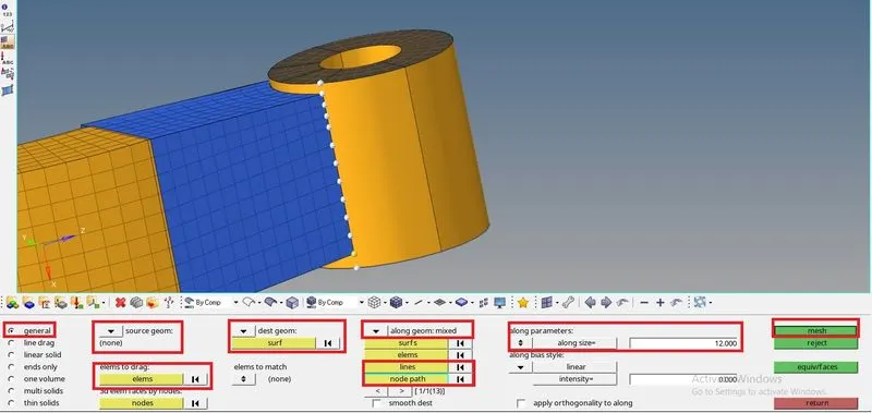
We can see that a new collector has created of 3D elements of the boss, so we can organise those elements to boss components.
STEP 12: Deleting 2D elements from the whole arm bracket component.
- Mask 3D elements by config hex 8.
- Delete 2D elements as it is shown unmasked.
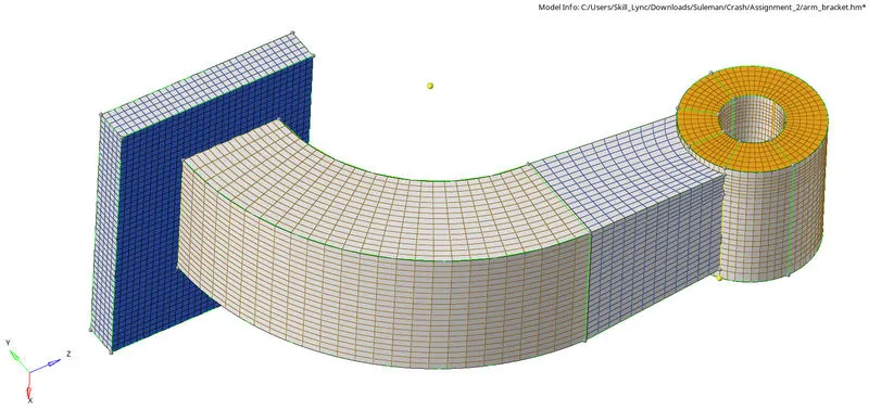
- We can see that whole arm bracket is consist of 3D elements
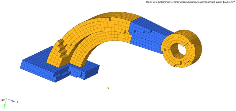
PROCEDURE FOR OBJECTIVE 5 : 3D Mesh of Housing components with target tet size 5 mm and tet collapse 0.15
STEP 1: 2D mesh on cover with 5mm tria elements.
*2D>automesh>select surface(displayed)>element size(5mm)>mesh type(trias)>mesh
STEP 2:Now we have to proceed for 3D tetramesh by tetra mesh panel
*3D>tetramesh>tetramesh>select elements(displayed)>simply pyramid>mesh
- We can check 3D tetra mesh by masking an amount of elements
*Tools>Mask>select elements>mask or F5

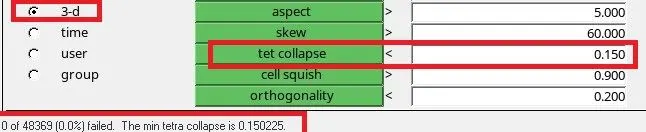
STEP 3: Now we have to also check for tet collapse if any, if yes then we have to fix that particular element
*Tool>check elements>3-d>tet collapse(0.15).
- There should be zero elements failed.
STEP 4: 2D mesh on hub with 5mm tria elements.
*2D>automesh>select surface(displayed)>element size(5mm)>mesh type(trias)>mesh
STEP 5: 3D tetramesh by tetra mesh panel
*3D>tetramesh>tetramesh>select elements(displayed)>simply pyramid>mesh
- We can check 3D tetra mesh by masking an amount of elements
*Tools>Mask>select elements>mask or F5

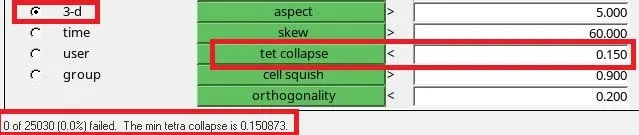
STEP 6: Now we have to also check for tet collapse if any, if yes then we have to fix that particular element
*Tool>check elements>3-d>tet collapse(0.15).
- There should be zero elements failed.
NOTE: 3D mesh can be also obtained by Tetra Mesh from Utility Panel, Volume Tetramesh Panel.
RESULTS OF OBJECTIVE 3:
RESULTS OF OBJECTIVE 4:
RESULTS OF OBJECTIVE 5:
LEARNINGS:
From objective 1
- Reading and writing starter and engine file.
- Calculating speed of sound
From objective 2
- Calculating elemental time step
- Calculating Tfrequency
From objective 3
- Creating 1D RBE2,RBE3,Spring,rod elements.
From objective 4
- 3D element offset panel
- 3D spin panel
- 3D linear solid panel
- 3D solid map panel
- Masking elements by configuration
- Creating circle center node by using distance three node option
- Projecting node by project panel
From objective 5
- 2D meshing
- 3D meshing
- Checking and correcting tet collapse