Assignment 2-RADIOSS Engine File Editing & 3D Meshing Challenge
MODULE 1
1. Check the material properties of the rail component and calculate the speed of sound in steel rail
2. The length of the rail is about 1000 mm.calculate the time takes for a shock wave to travel from one end of the rail to the other.
3.Time for sound to travel length of rail
4.Edit the engine file so that the stress wave can be monitored, moving from one end of the rail to the other during impact -this will require a termination time equal to the time it takes for the sound to travel the length of the rail(set on/RUN card)
Check the material properties of the rail component and calculate the speed of sound in steel rail
TO check the material properties of the rail component ,we have two ways to extract parameters
1 To extract the material [roperties by just opening the FIRST_RUN_0000.rad in notepad
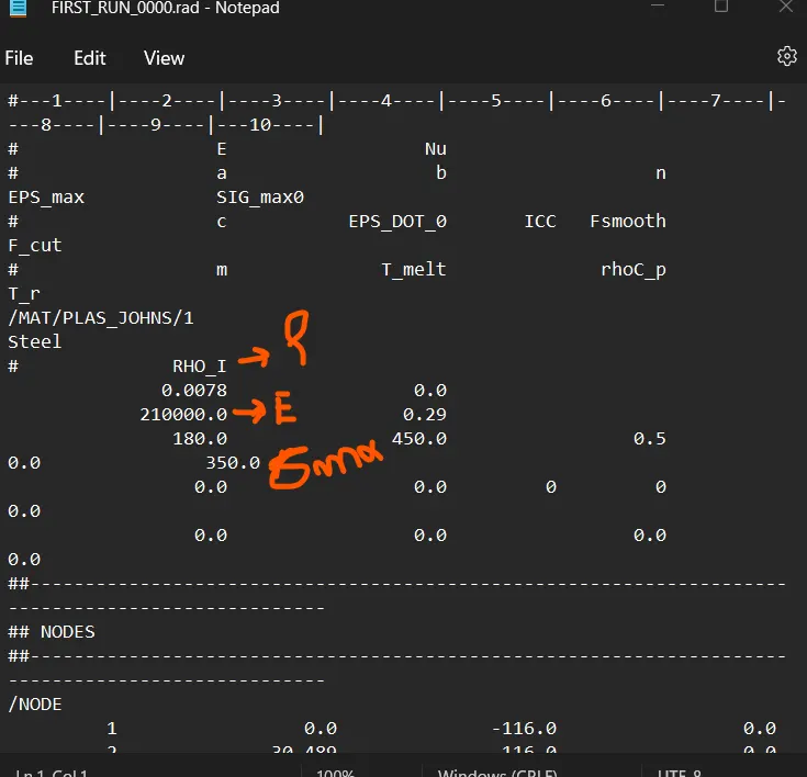
The other way is to open the FIRST_RUN _0000.rad in Radioss to see the material properties
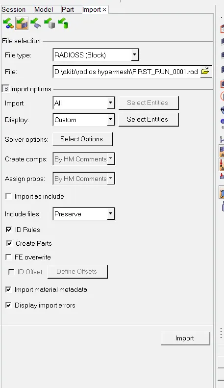
start the hypermesh>select the import option >select the option solver deck>choose the file FIRST _RUN_0000.rad and click on import option
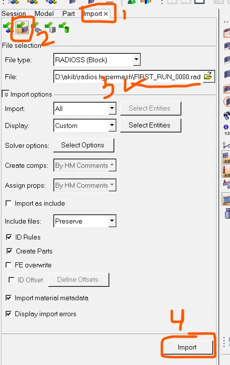
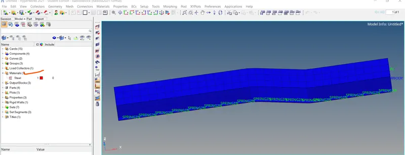
once the FIRST_RUN_0000.rad file has been imported you will be able to view the material properties in the model browser
now to check the material properties of the rail component click on steel and window will open below
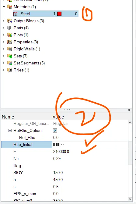
here we can see the density of the material rho=0.0078 g/mm^3
youngs modulus (E)=210000Mpa(N/mm2)
to calculate the speed (c) of sound in the steel rail
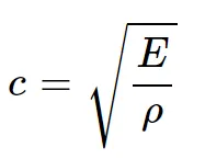
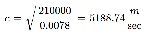
time taken for shock wave to travel through the rail component having length of 1000mm
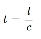
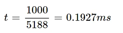
in the above calculation time taken to complete one animation=0.1927milli sec
in order to get 20 animation steps we need to divide the one animation cycle to 20
therefore time step for 20 animation=0.1927/20=0.009635ms
what will be the frequency of animation output to a time that will give 20 animation steps
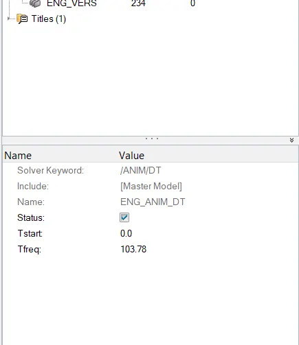
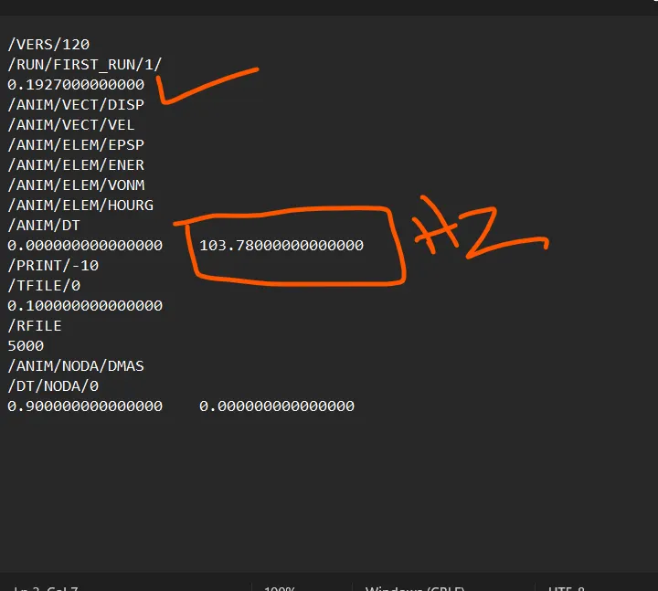
frequency(f)/animation=1/0.009635=103.78hz
now we have to set the above frequency in the engine file (0001.rad file )
import the 0001.rad file
once we import the 0001.rad file we can easily change the values as showne in the below snaps
click on eng_anim_dt set the frequency to 103.78
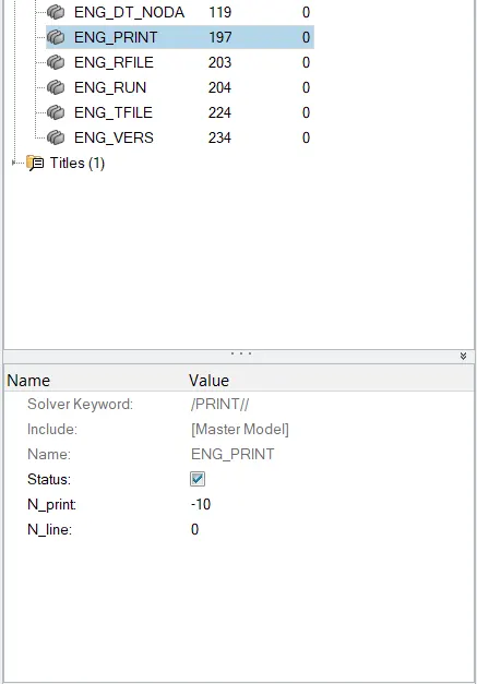
click on the ENG_PRINT check the value of N_print ,the defaulted value is -10 and we donot need to change this
we can easily change the values of frequency from the 0001.rad file we need to open this file in the notepad
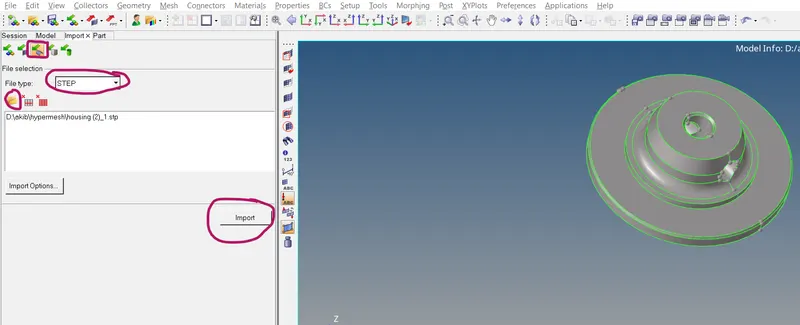
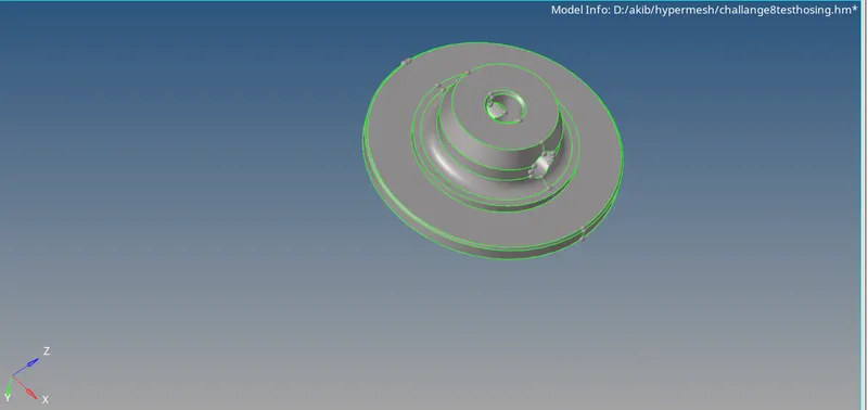
we have successfully imported the STEP file now we are going to check the model very carefully to fix the free edges if present and also we are going to remove unnecessary lines by using the toggle option or various other cleanup tools
process to find out the element failure since the minimum element size is 2 thus below 2 units will fail the elements
click on F4 >select 2 point option >select the point on the component to measure the distance
the distance we have measured is 2.23 and element failure will not occur in this region
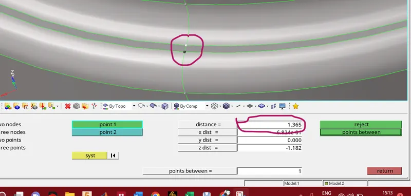
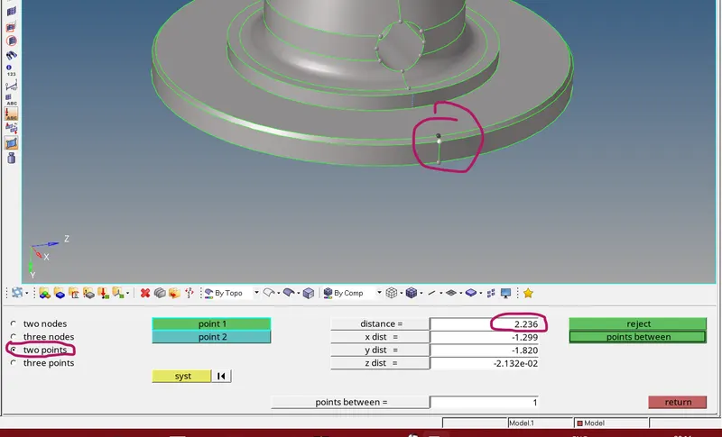
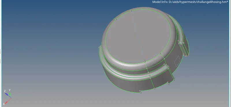
we have succesfully clean up the geometery and remove the unecessary lines from the model now we are going to generate surface mesh
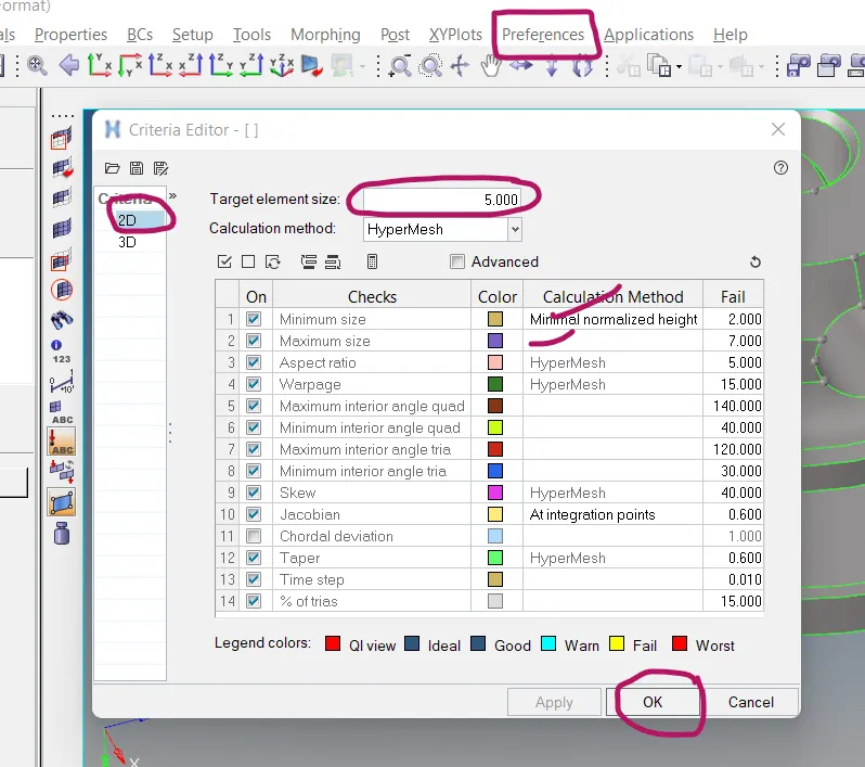
To set the quality criteria .click on preference >select criteria file editor>click on 2D
target element size =5 units
minimum element size=2
maximum element size=7
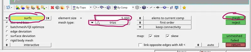
2D mesh generation process
click on 2D>select automesh

click on suface >select element size=5units>select mesh type trias>click on mesh
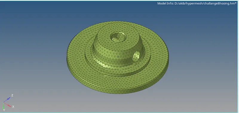
now 2D mesh has been generated
now we are going to check the quality of the elements
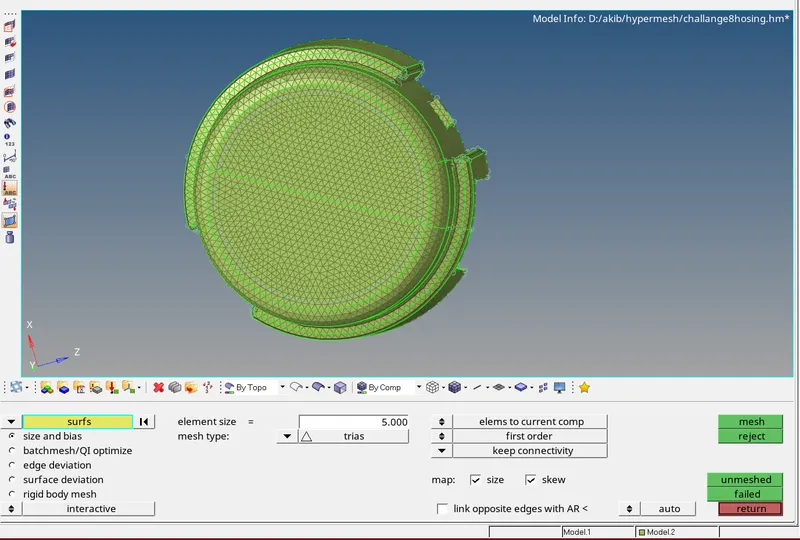
process to check element quality
click on F10
click on minimum length (2 units in our case )
there are almost 47 elments failed in the minimum length criteria
now we are going to fix these elements
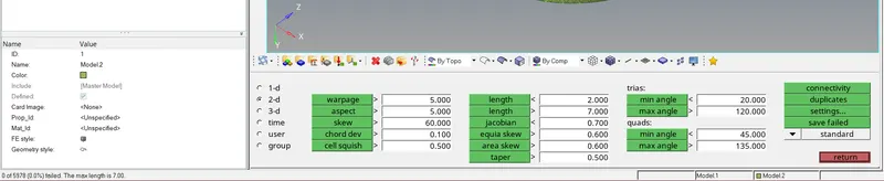
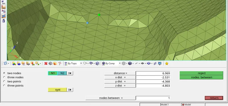
click on F4 (this will take us to the node edit pannel)
select the option 2 nodes
select the node of the failed element ,green node indicates fixed node where as the blue will move according to minimum and maximum lengthe that we can set in the distance box
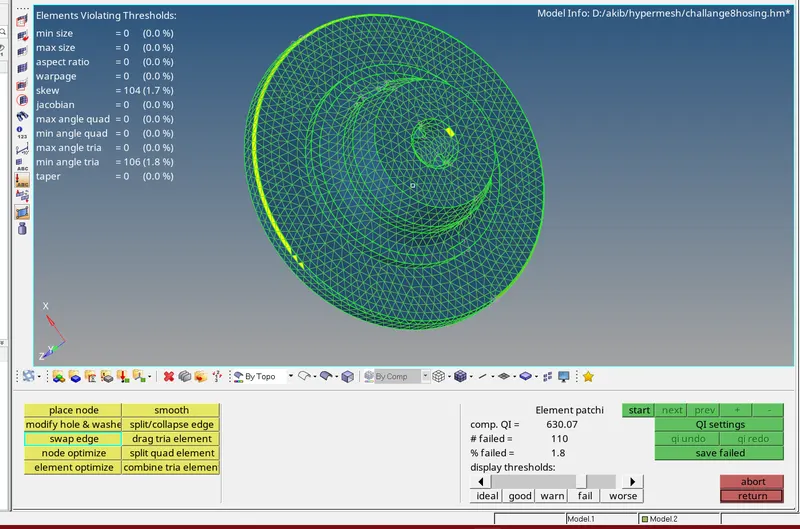
minimum and maximum element failure has been fixed and this can be seen from the image below
process to transform 2D mesh to 3D
click on 3D from the pannel >click on tetra mesh
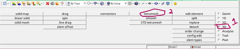
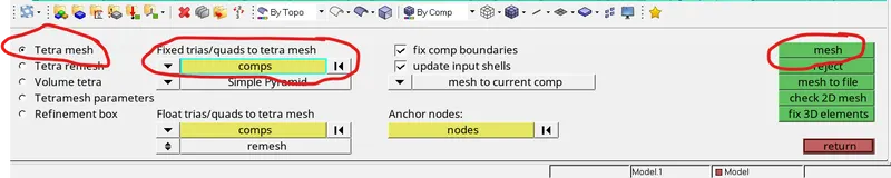
click on tetra mesh>select the component>click on mesh
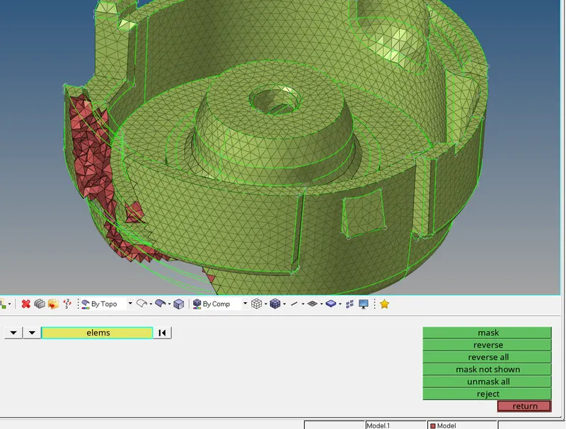
the 3D mesh has been generated in order to see the 3D elements click on mask option >select the elemens >select the mask
in order to check the element quality click on F10 >select 3D >select tet collapse(0.15)

as we can see from the image 0 elements are failed from tet collapse
we have successfully generated the 2D mesh on housing and conversion of 2D mesh TO 3D tetra mesh.The mesh quality has been improved by using quality tools
MODULE 3
intially we are going to import model into the hypermesh GUI
after importing the model we neen to set the model in topo mode to check the free edges and defected surfaces
there was no free edges and we proceed for the meshing
procedure for 2D automesh
set the base as current component
press F12 >select automesh >set element size=5>click on the surface and hit on mesh
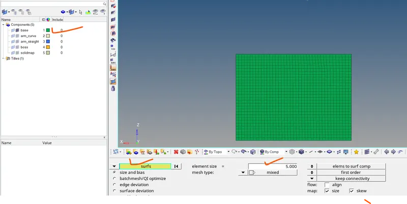
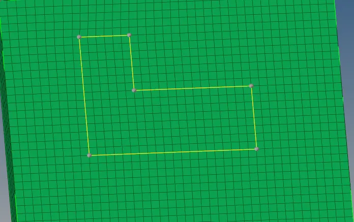
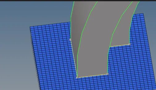
now we are going to drag these 2d elements along the thickness of the base
procedure to drag the 2d elements
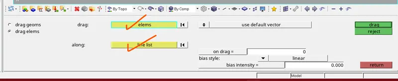
click on 3d from the pannel>select line drag >click on drag elements >select all the 2d elements >select the line along drag >click on drag option and set no of elements =5>now hit the drag
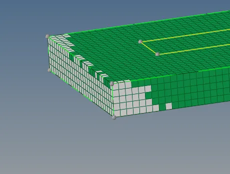
we have succesfully drag the 2d elements along the thickness of the component
now we are going to mask the 3d elements and we left with 2d shell elements ,we need these 2d shell elements for the arm so that we can spin them along the surface of the arm and finally convert them into 3d shell elements
we need and a node along which we are going to rotate /drag the 2d shell elements
set the arm bracket as current component
to create a node we need to press on F4 from keyboard and select three node option
now we need to select the line on which we are going to place those three nodes and and extract the circle center for the base purpose
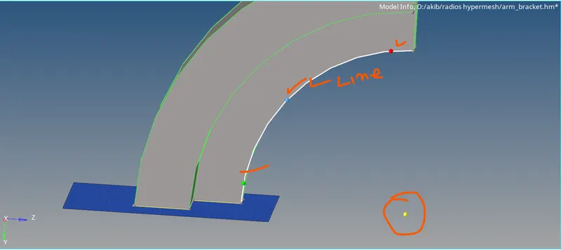
to drag the elements from the base we need to select the 3d option >select spin option >select spin elements >select 2d elements from the base component>set the angle as 90 deg>set on spin =25>hit spin -

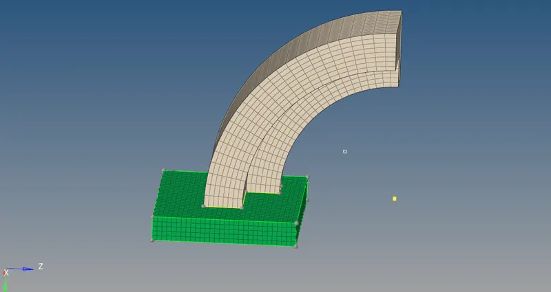
now we have mesh the arm straight component for that we have to make arm straight component as current
to drag the elements from the arm we need faces of the arm that can represent 2d shell elements
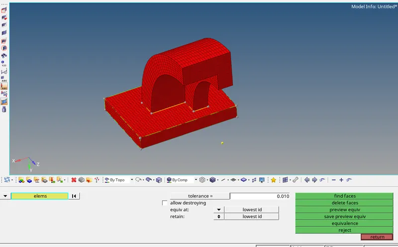
once we get the face of arm curve we can map them with the other face of arm straight
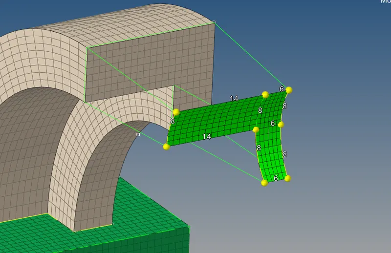
from the above snap we have mesh the front face of the arm straight with 2d elements
the elements on the front face of arm straight should match in all the sides with the front face of the arm curve
once we match the elements now we can drag the elements from the front face of arm curve to the front face of the arm straight
procedure to drag the elements
Click on 3d from the pannel select >click on linear solid >click on 'from elements' and select all elements from face and for alignment select the 3 node from the face
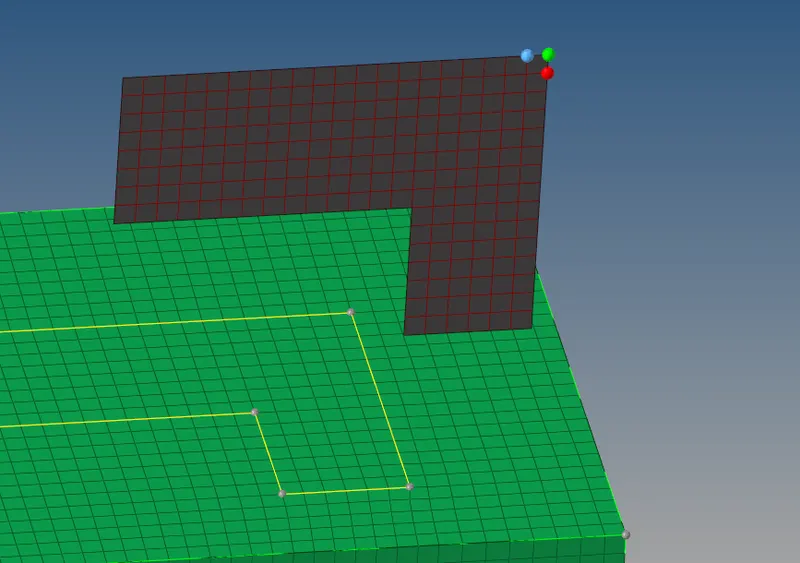

similarly we can select the elements from the front face of the arm straight and for allignment we are going to select the node at the top right of front face of the arm straight
we have to set the density =12
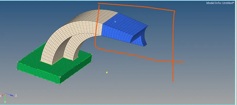
now we are going to mesh the boss
click on 2d and select the automesh >set element size=5>mesh type =quard>select the side face of the boss component and hit on mesh
important to note
if we are going to drag the elements in the boss component we may loss the connectivity between boss and arm straight also if we are going to toggle any line after 2d mesh the mesh is going to deform. to keep the mesh as it is before and it should be same after toggle operation of any line .we need to press 'o ' from the keyboard>select the option mesh under which we need to click on topology revision from the drop down arrow select keep mesh
and you are ready for toggle operation

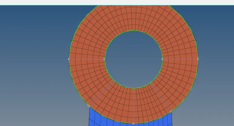
now we are going to drag the elements from the face of the boss to the other face
procedure
click on 3d select solid map>select general>select the source geometry(2d shell element face >select other face as dest geo>select elements to drag >select elements to match as none>select along geom as node by path and select the nodes (select nodes from cross section of arm straight >now hit mesh
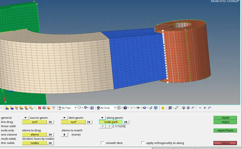
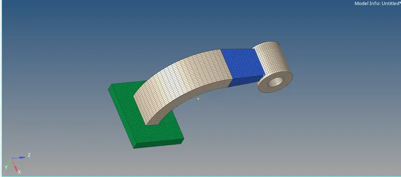
at the end we need to check free edges , we need to delete the faces and we also need to delete 2d shell elements
i have checked connectivity before submitting the challenge