Assignment 2-RADIOSS Engine File Editing & 3D Meshing Challenge
RADIOSS Engine File Editing & 3D Meshing
Objective:
1. Check the material properties of the rail component and calculate the speed of sound in steel rail=_______
2. The length of the rail is about 1000 mm.calculate the time takes for a shock wave to travel from one end of the rail to the other.
3.Time for sound to travel length of rail=______
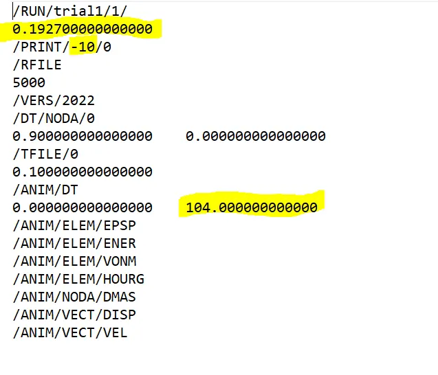
4.Edit the engine file so that the stress wave can be monitored, moving from one end of the rail to the other during impact -this will require a termination time equal to the time it takes for the sound to travel the length of the rail(set on/RUN card)
5.Set the frequency of animation output to a time that will give 20 animation steps(/ANIM/DT)
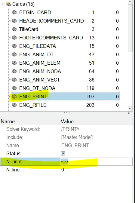
6.Change /print -10.
7.3d meshing tetra mesh and hex mesh
- Repeat class examples and, maintain the quality.
- Target tet size=5mm,hex size=10mm,tet collapse=0.15.
Solution:
1) For calculating speed of sound in still rail;
'Speed of sound', C= √E/ρ
from the file ,
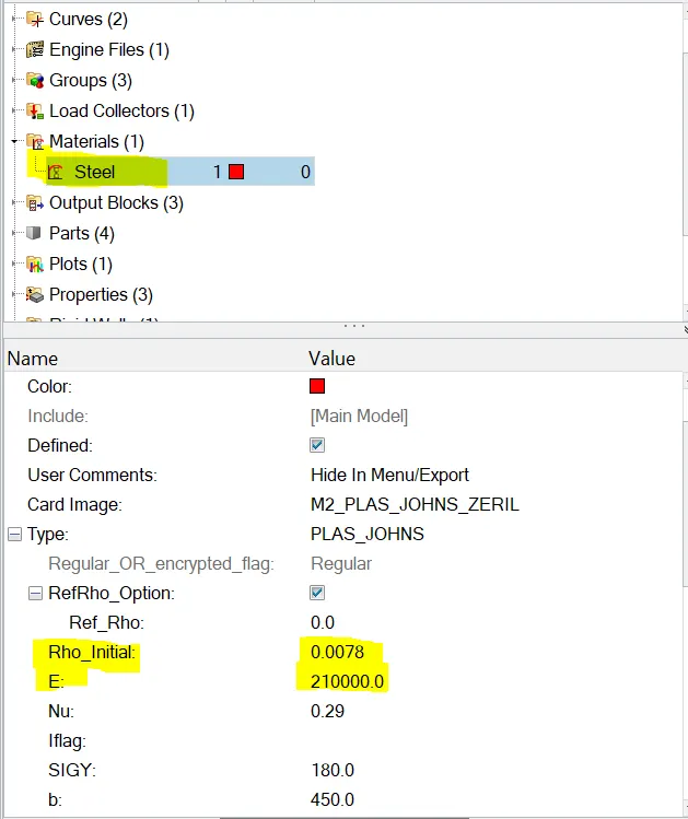
for steel, E= 210000.0 MPa
ρ= 0.0078 g/mm^3
∴ C= √210000/0.0078
∴ C= 5188.75 m/s
speed of sound in still rail is 5188.75 m/s .
2) For the time takes for a shock wave to travel from one end of the rail to the other of length 1000mm ;
Speed = Distance/Time
∴ 5188.75= 1000/ T
∴ T= 0.1927ms
3) Time for sound to travel length of rail= 0.1927ms.
4) Following is the updated engine file as per above calculations;
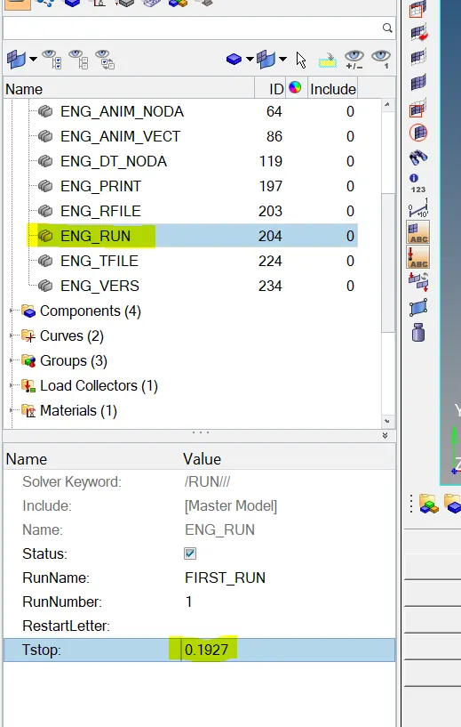
5)Set the frequency of animation output to a time that will give 20 animation steps;
Frequency= (1/time)* no of steps
= (1/0.1927)*20
= 103.788≈ 104 Hz.
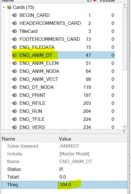
6) Change /print -10
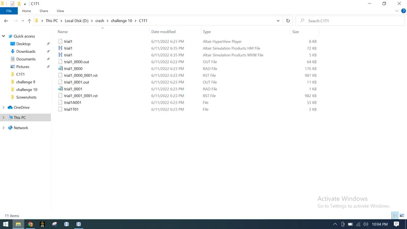
Now after updated all the changes the file is run under radios analysis which leads to generation of following folders,
the file name trial_0001.rad can be opend in text document to confirm the changes ;
Case 2:
3d tetra mesh generation with;
- Target tet size=5mm
- tet collapse=0.15.
Procedure:
Steps to be followed: Import Geometry > Perform Geometry CleanUp > 2D automesh > Check for minimum length > Rectify (Check Elements )> Minimum Length > Save Failed > Mask Elements > Retrieve > Mask > Reverse > Rectify) > 3D Tetramesh > Rectify.
1) Meshing the housing component to meet the given quality criteria:
- Import the geometry into hypermesh. Delete Solids if any.
- Check for any surface errors and perform the geometry cleanup if required. Set the geometry in By Topo Mode.
- If the fillits in the geometry are less than minimum mentioned size limit, it is recommended to defeature them.
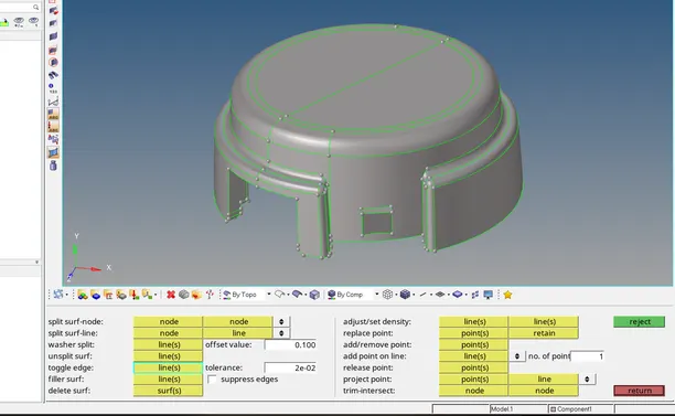
- Once the geometry cleanup is done the next step to be processed is to perform 2d Automesh (only tri) according to mentioned quality criteria. After the mesh is performed, for better mesh quality rebuild mesh and check for minimum length and rectify the mesh quality.
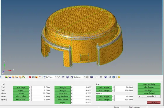
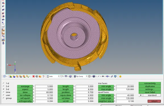
In the above mentioned image, 0 elements have failed for 2D minimum length. Now we move further with 3D tetramesh using the criteria of tet collapse as 0.15.
3D Tetramesh > mesh using elements displayed.
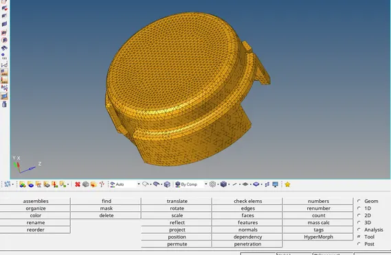
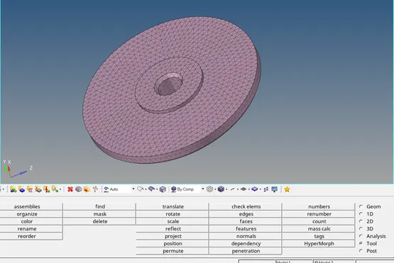
Similarily, for other component:
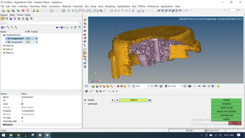
Final meshed geometry obtained :
Case 3:
3d Hexa mesh generation with;
hex size= 10mm
- The 3D Hexa mesh generation for the give model is followed is 4 steps , that is one component at a time and 4 components are need to be meshed.
- The first component need to be meshed is the base.
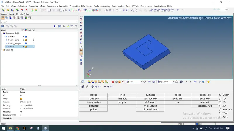
- Since the geometry is simple it is preffered to mesh the shell element and then coonvert into a 3d mesh as shown below;
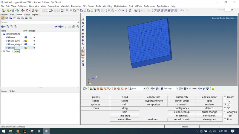
- for the second compont the geometrry is curved in shape so the operation to be performed for mesh generation is SPIN.
- To spin the geometry the most important required feature is the centre of rotation, the centre of node can be generated by getting a circle centre by measuring three random points on an Arc.
- After the point is generated the geometry is ready to spin as shown below.
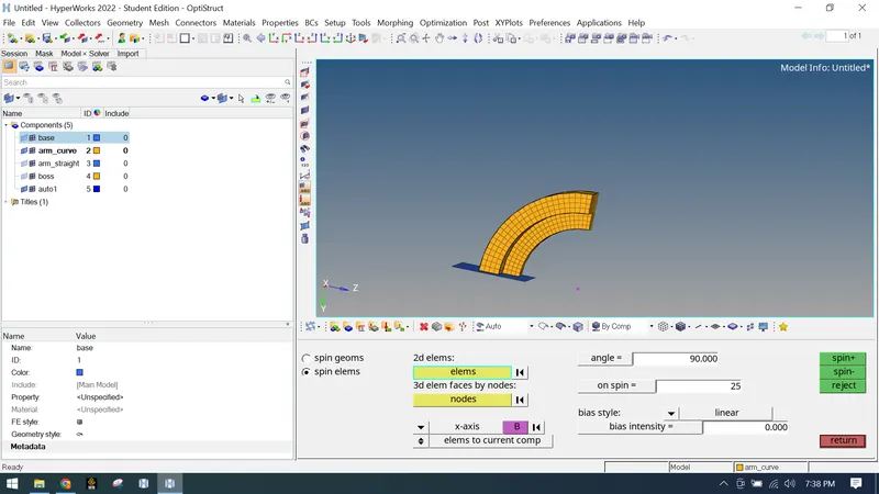
• To mesh the arm straight component, 3d›linear solid option can be used,
• Each end of the straight part is needed to be meshed by 2d element.
• 3D element from hexa element can be used to genarate 2D mesh to perform the operation , to generate 2D mesh following is the process to be followed tools >faces >extract faces
• For the other end mesh the same number of elements and nodes in the mesh is impoortant.
• After the mesh is generated , three nodes from each of the mesh is selected for alignment as shown below.
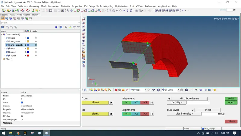
• Now the geometry is ready to be converted into solid as shown below,
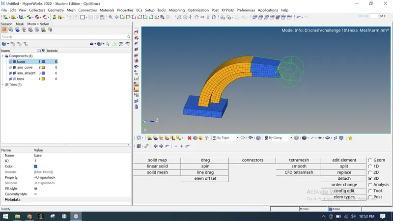
• Solid map feature can be used mesh boss
• 2d Mesh the one side of boss and once meshing is done he nodes are need to be projected along with the mesh nodes can connect.
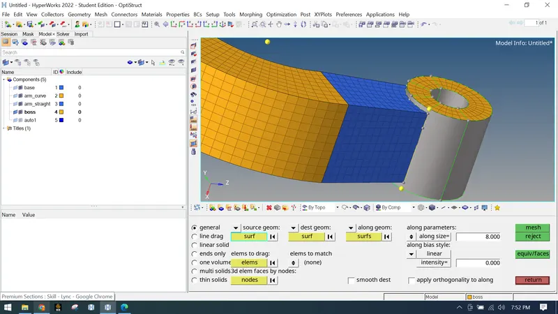
• Now the 2D mesh can be converted to 3D along the straigt line and node by paths feature.
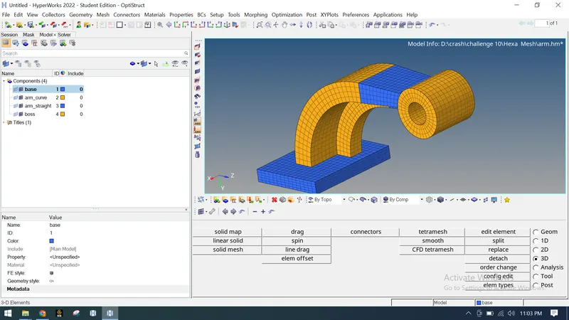
• Now after meshing all the components by hexa elements, delete all the 2d elements present in the
model.
Conclusion:
• Calculated speed of sound in different material, frequency, time step
• worked on understanding and reading input radioss file
• Exported the file in .rad format
• Created 3d tetra mesh and hexa mesh using verious procedures.