Assignment 2-RADIOSS Engine File Editing & 3D Meshing Challenge
1. Check the material properties of the rail component and calculate the speed of sound in steel rail.
Import the given Radioss file into the GUI, File>import solver deck> Select file type> Import
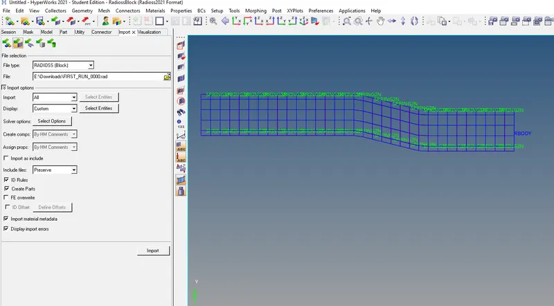
Now to check for the material property of the given component, to calculate the speed of the sound in steel
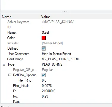
Material is steel:
Given:
E: 210000.00 MPA
Nu: 0.29
Rho:0.0078 kkg/l
Formula :- C= Sqrt(E/ρ)
= sqrt(210000/0.0078)
= sqrt(2,69,23,076.923)
The speed of sound in steel rail (C) =5,188.75 m/s
2. The length of the rail is about 1000 mm.calculate the time takes for a shock wave to travel from one end of the rail to the other.
Given:-
l=1000mm
Formula:- T=l/c
=1000/5188.75
Time taken T =0.1927s
3.Time Taken for sound to travel length of rail T =0.1927s
4. Edit the engine file so that the stress wave can be monitored, moving from one end of the rail to the other during impact -this will require a termination time equal to the time it takes for the sound to travel the length of the rail(set on/RUN card)
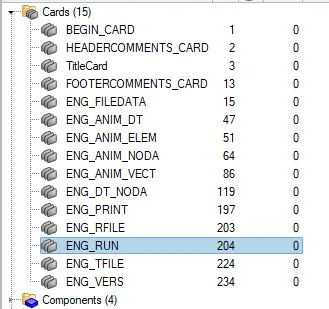
Expand Cards From Model browse> ENG_Run.
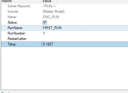
Editing the Tstop or termination time is equal to time taken for the sound to travel the length of the rail.
Tstop=T=0.1927
5.Set the frequency of animation output to a time that will give 20 animation steps(/ANIM/DT)
Animation steps= 20
Formula: Tfreq = Tstop/ No of animation step.
= 0.1927/20
Tfreq = 0.009635s
Now to edit the value of the Tfreq in from ENG_ANIM
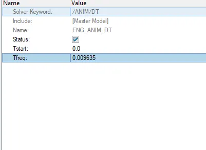
6.Change /print -10.
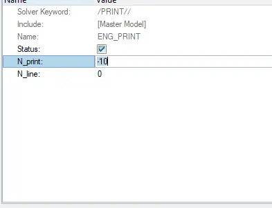
7.3d meshing tetra mesh and hex mesh.
OBJECTIVE: To Create a Tetramesh from 2d tria mesh to 3d tetramesh for Housing component.
PROCEDURE:
Step1: To import the model give model to the interface or GUI.
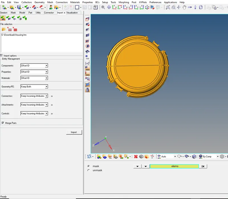
- Import>import the model select the file type and import.
Step2: Generating the tria mesh on the surface which is the 2D mesh.
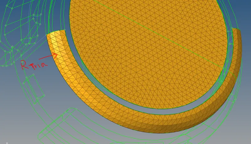
- Geom>2D mesh element Size 5 units> selecting the surface
- Using R tria in Edge fillet to capture the fillet.
Step3: Now generating the 3d mesh for the components.

- 3d>tetramesh>Selecting the 2d elements > Mesh
- The 3d Tetra mesh is generated.
Step4: Checking for tet collapse which is the element is failure in 3D mesh.
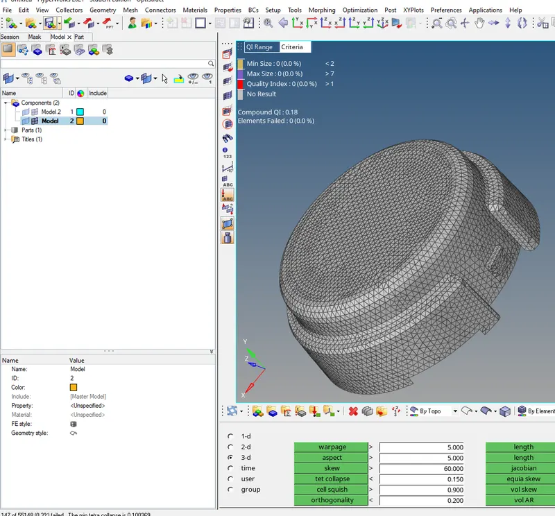
- F10 or Tools>check elements>entering the tet collapse value>selecting the tet collapse>save failed.
- F5 or Tools>mask>elements>retrive>mask>reverse.
- The failed elements are shown
- Removing Tet collapse by translate option and tetra remesh option
Pictures of the Model:
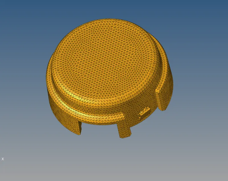
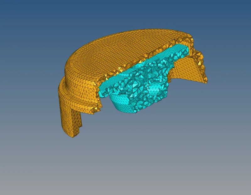
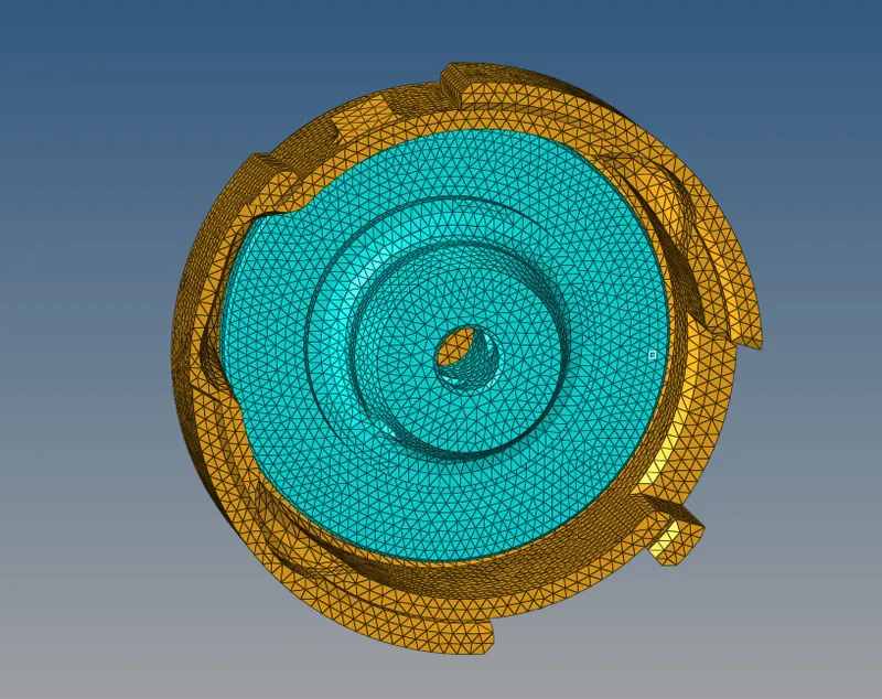
RESULT: Successfully meshed the components with a tria element (2D) and then converted into tetrahedral or 3D mesh with the given Quality and mesh parameters.
Hexa Mesh
OBJECTIVE: To Create a Hexamesh from 2d quad mesh to 3d Hexamesh for component.
PROCEDURE:
Step1: To import the given model to the interface or GUI.
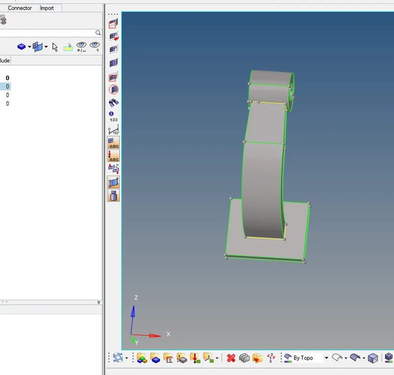
Step2: To mesh the pedal with the 2D quad.
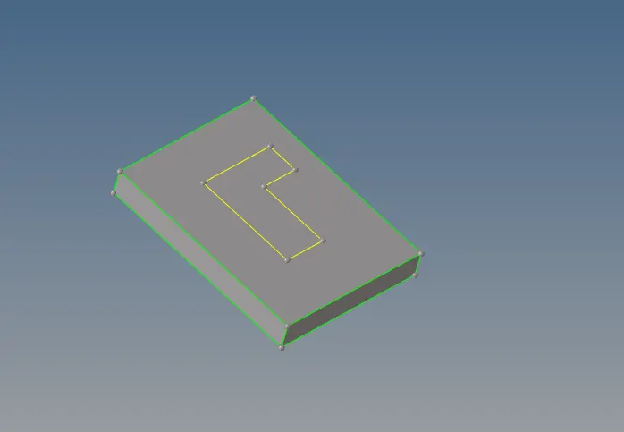
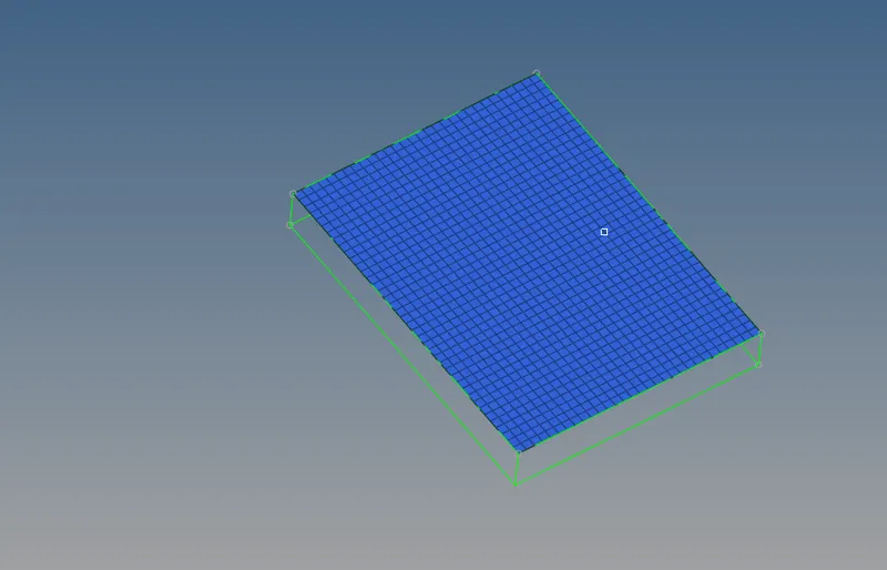
- Geom>2D> Mesh size 10mm> Select quad only.
- 3D> element offest selecting the elements and the surface to be followed and number of layers.
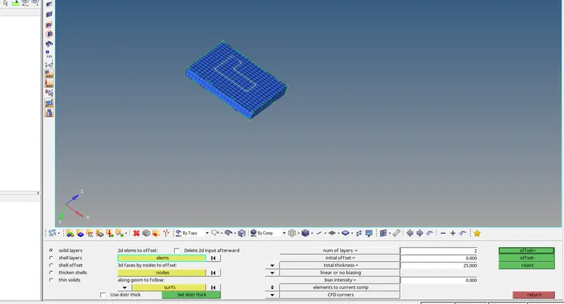
- Now Hexa mesh is created or solid mesh.
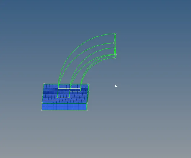
- Now to mesh the above component and generate the hexa element.

- Now to have only 2D elements in oder to Spin the elemts to create the hexa mesh.
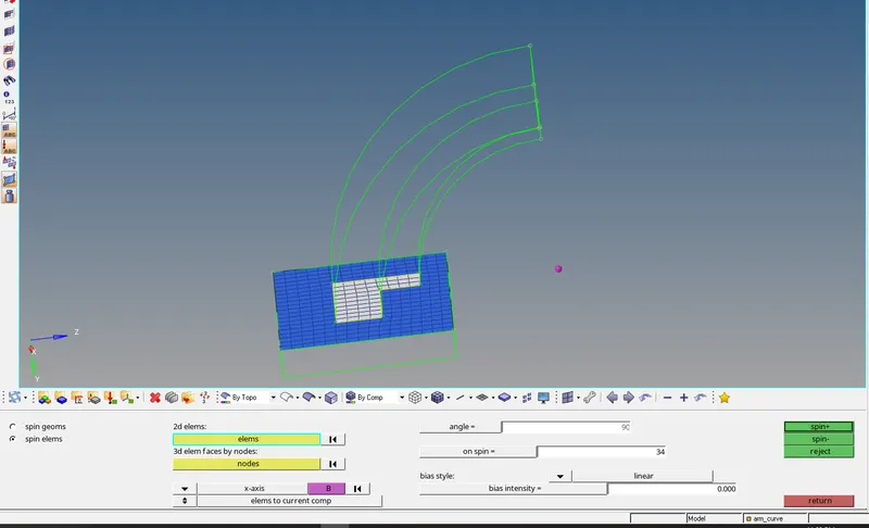
- Using mask option or F5> select elements> By config>Hex8 to hide the elements>displayed>Mask.
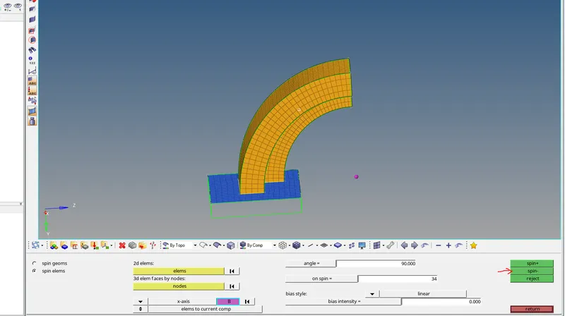
- Now to create the node for the axis of rotation
- Using Geom> distance or F4 >three node option>circle centre> the node is created.
- The axis is selected Perpendicular to golbal axis of rotation
- 3D>spin> selecting the elements to rotate > selecting the base point and also providing the angle and the number of elemts to creat> Spin.
- The hexa elemets are created.
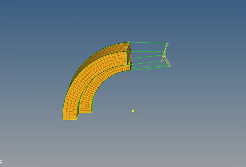
- To create the hexa mesh for the varing cross section component as shown above.
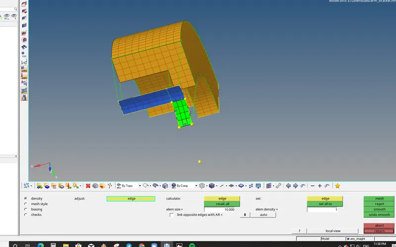
- Now to mesh the other side of the component with 2D Elements
- Matching the elemets on the other end of the face to avoid the penta elements.
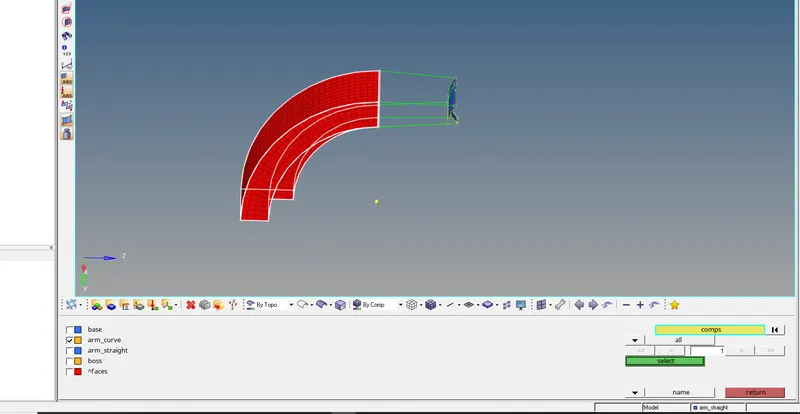
- Tools> Faces>selecting the components>Find face to create the 2D elements.
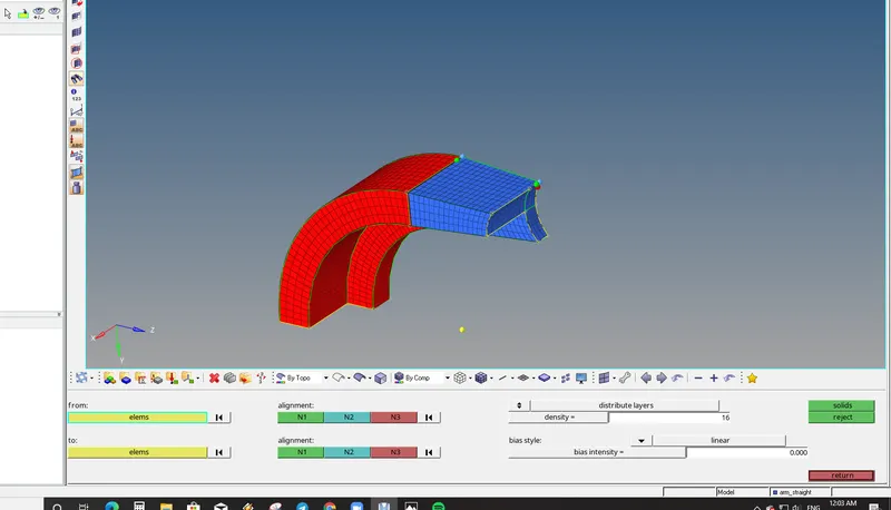
- 3D> Linear solids> Selecting the elements from one side and also selecting the other elements on the other side.
- The Hexa mesh is created in varying cross sections.
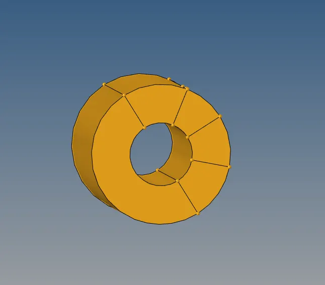
- Now to mesh the above component with the Hexa mesh.
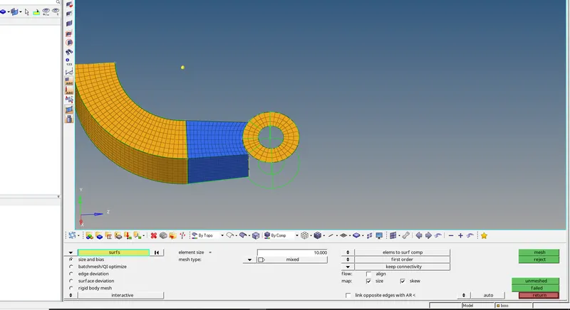
- 2D> mesh> Element size> meshing the surface using 2D qauds.
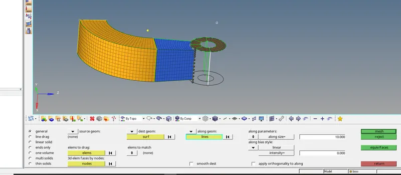
- 3D> Solid map> general> selecting the nodes to drag along the geom.
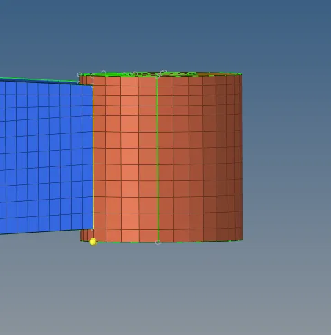
- Now Hexa mesh in genrated in the boss component.
Pictures of the Model:
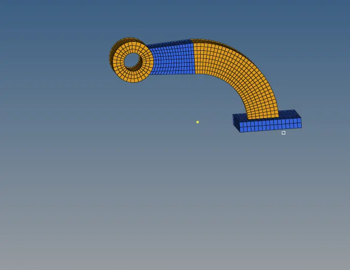
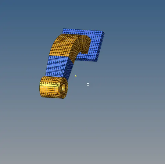
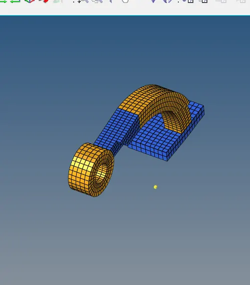
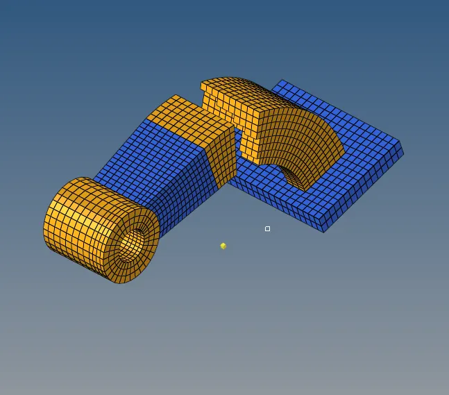
RESULT: Successfully meshed the given components with hexa mesh.
CONCLUSION:
- Tetra mesh are used for complex shapes and features and Hexa mesh are used when the geometry is symmetric and with less features.