Assignment 2-RADIOSS Engine File Editing & 3D Meshing Challenge
OBJECTIVE:
Check the material properties of the rail component and calculate the speed of sound in steel rail
To calculate the time takes for a shock wave to travel from one end of the rail to the other.
Time for sound to travel the length of the rail
Edit the engine file so that the stress wave can be monitored, moving from one end of the rail to the other during impact -this will require a termination time equal to the time it takes for the sound to travel the length of the rail(set on/RUN card)
Set the frequency of animation output to a time that will give 20 animation steps(/ANIM/DT)
Change /print -10.
3d meshing tetra mesh and hex mesh
- Repeat class examples and, maintain the quality.
- Target tet size=5mm,hex size=10mm,tet collapse=0.15.
CALCULATIONS:
1. Speed of sound in steel rail :
The formula for speed of sound is C=√E/ρ
where E is young's modulus and ρ=density
Import the given 0000.rad file to the radioss profile in hypermesh and we can get the material properties .
From the material, we can see that the value of E =210000 Mpa(N/mm^2)
ρ=0.0078g/mm^3
Substituting the above values in the formula C=√210000/0.0078=5188.745m/s
2.Time taken for the shock wave to travel from one end to another:
Time =Distance of the rail /Speed of shock wave
D= 1000mm
C= 5188.745
time = 1000/5188.745 =0.1927s
3. Time for Sound to travel the length of rail = 0.1927s
4. Edit the engine file:
5. Set the frequency of animation output to time that will give 20 animation steps:
frequency=time/no.of revolutions
=0.1927/20
=0.009635
6: change/print -10
The value is by default -10 , so it doesnt need to be changed.
7. 1DConnector, Tetra and Hexa mesh
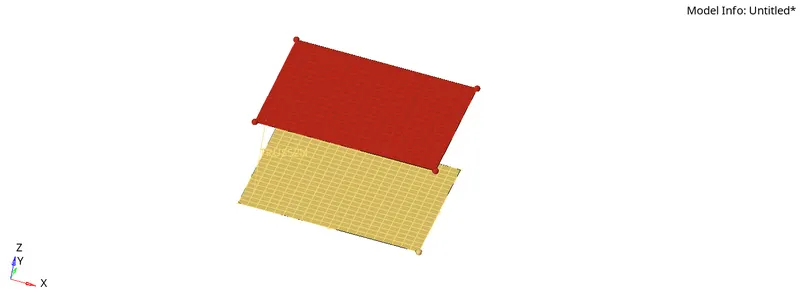
1d CONNECTOR:
- To mesh the given file and connect it using 1D connectors.
- Open the given .hm file in hypermesh
- Mesh both the surfaces
- Go to 1D- connectors-rods and select any two nodes to connect.
- now the connection is done, after which the property card should be assigned to the component, new hyberbeam has to be created, go to hyperbeam and select required cross section and give dimensions.
3D Tetra mesh
Open the model in the hypermesh.
using the topo mode check for any geometrical errors or missing surfaces in the component.
mesh the component with 2D tria elements according to the given quality criteria.
After that we have to convert 2D to 3d tetra mesh, select 3D-tetramesh select elements and provide the tet collapse for quality criteria.
Do the sameprocedure for all the components and convert it into tetramesh and check for quality errors.
3D hexa mesh
In this model, there are 4 components that should be meshed individually.
It is meshed using different methods like element offset, Linear solid, solid map, spin, etc.,
First, the base is to be meshed, the surface of the base has meshed first without any tria elements and only quad elements.
Now using 3D-Elem offset-solid layers, the 2d shell mesh is converted Hexa mesh with giving thickness and layers
Next, the curved shape in the component is meshed , for that a point of reference is obtained using Geom-nodes-arc center
After taking out the arc center using 3d-spin-spin elements, the elements in the base are selected and layers and degree of spin is given and it is spinned
for the third section, the shell mesh of the curve is required to get the shell mesh tools-faces -elements are used and it is created which is hollow on the inside
now to mesh section three the rows and columns must be the same as the rows and columns of section 2 (curve) face and mesh with shell elements
Go to 3d-linear solid the form elements and to elements are selected from both faces of the 2d shell elements. the alignment node should be the same for both faces.
density is set for the Component.
the next component is the boss. solid map is used for meshing this component
The first one side of the component has meshed with quad elements only
now with the help of the solid map option, the destination surface, the elements to be mapped, the nodes for connectivity and the lines along which the surface is meshed is selected
after generating the Hexa mesh the connectivity between the Section 3 and boss element is checked
the final model is meshed with Hexa mesh
Conclusion
Generated a 3D mesh using tetra and Hexa elements by following given quality criteria on given models.
Learning outcomes
calculations such as speed of sound, frequency, time step is calculated using formulas
editing of engine file
3D meshing using Hexa and tetra mesh
Connect components using 1D connectors in Hypermesh.