Assignment 2-RADIOSS Engine File Editing & 3D Meshing Challenge
OBJECTIVE :
- To calculate the required parameters using the given values and to input those parameters in the Radioss Solver Deck.
- To Volume mesh th given 2 models (i.e)., Housing and Arm Bracket using Tetramesh and Hexamesh respectively.
PROCEDURE FOR A:
- Check the material properties and to find the Speed of sound in steel rail:
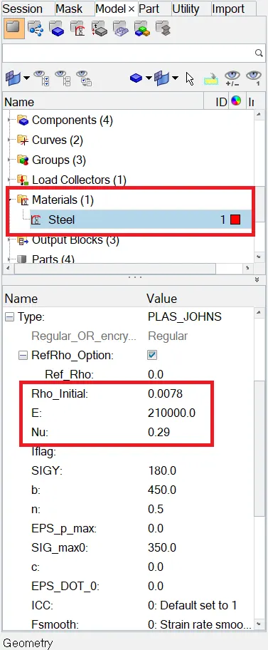
Given Data:
- Young's Modulus (E) - 210000 g/mm.ms^2
- Density (ρ) - 0.0078 g/mm^3
- Poisson's Ratio (ν) - 0.29
Formula :
c = `sqrt`(E/ρ)
c = `sqrt`(210000/0.0078)
Speed of Sound (c) = 5188.74 mm/ms
- To calculate the time taken for a shock wave to travel from one end of the rail to the other :
Given Data :
- Length of the rail - 1000mm
- Speed of sound - 5188.74 mm/ms
Formula :
Δt = Length of rail / Speed of Sound
Δt = 1000/5188.74
Δt = 0.1927 ms
- To edit the engine file so that the stress wave can be monitored, moving from one end of the rail to the other during impact :
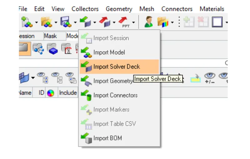
Initially the given input file is imported in the radioss solver deck and the cards are listed down that are assigned to the model.
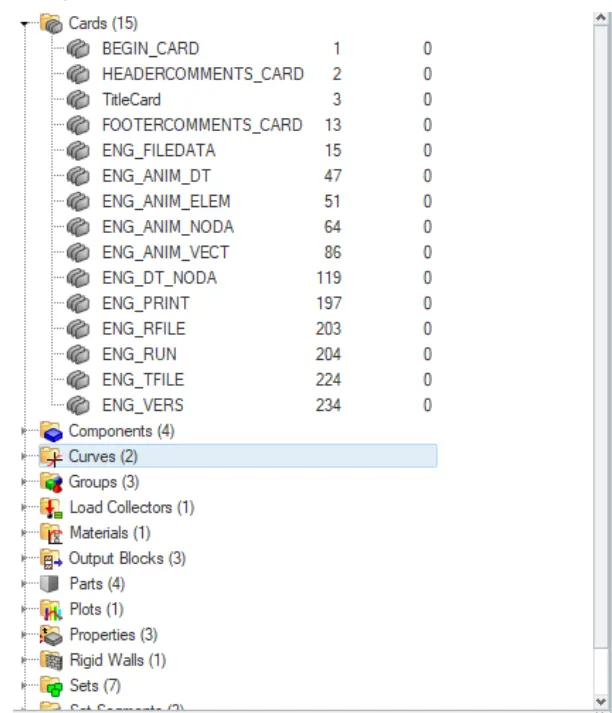
The values that are calculated and given as input in the card value are as follows.
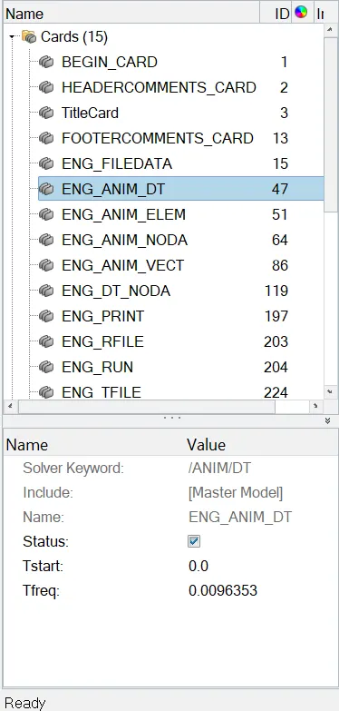
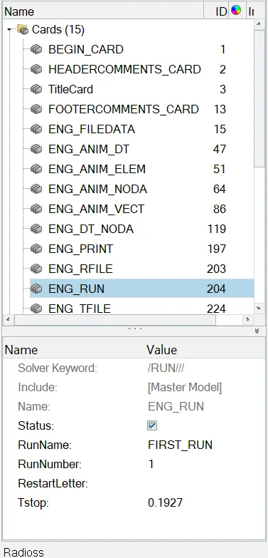
Finally after providing all these inputs, the model is run in the rodioss solver deck by following the steps as follows.
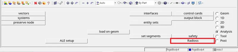
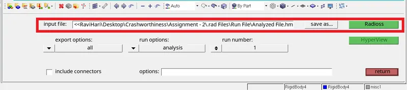
Radioss will send a pop-up after the task is completed. This indicates that the radioss job has been accomplished in the manner described.
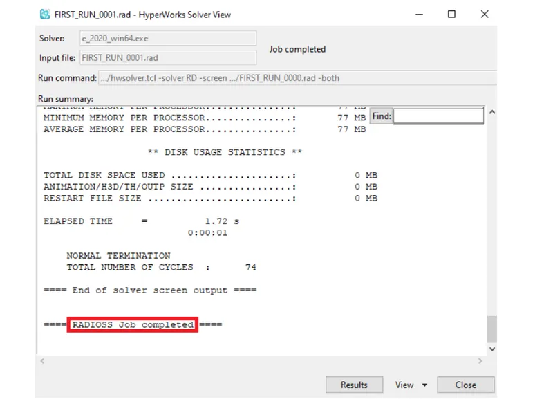
Now it's time to see if the engine file has been modified. Browse to the file location and open the "FIRST RUN 0001.rad" file which displays the engine file once it has been modified, as shown.
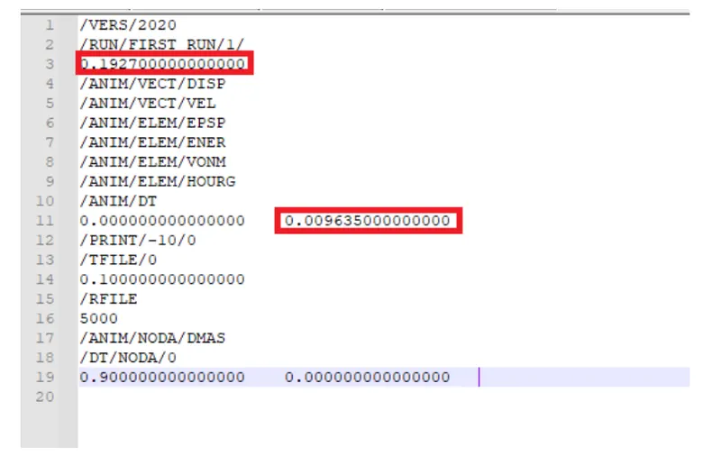
- To set the frequency of animation output to a time that will give 20 animation steps :
Given Data :
-
Animation steps (As)= 20
-
Time Stop (Ts) = 0.1927
Formula :
Time related to frequency of animation = Ts / As
Time related to frequency of animation = 0.1927/20
Time related to frequency of animation = 0.00963
- To modify the cycle with a 10 seconds difference in specific intervals:
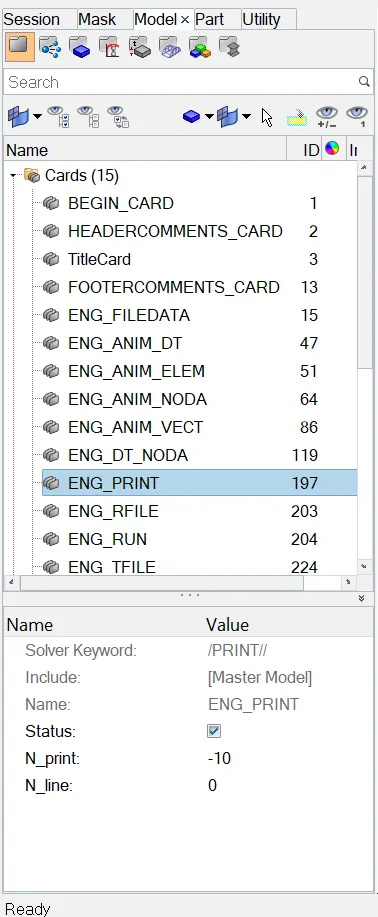
For modifying the intervals as 10 seconds, the ENG_PRINT card N_print value is changed as -10.
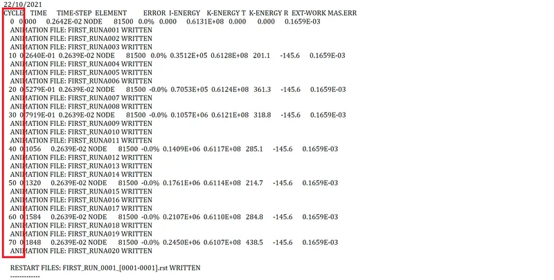
When the engine output file "FIRST RUN 0001.out" is opened, this can be noticed. As shown, the full cycle is represented as a set of specific cycles with a difference of 10seconds.
- 3D MESHING OF GIVEN 2 MODELS : HOUSING - TETRAMESH & ARM BRACKET - HEXAMESH
PROCEDURE FOR B:
MODEL 1 - HOUSING:
Steps to be followed:
- Import the given model using the Import Deck → Geometry → STEP type file → Browse and select the file → Click import.
- Check for any solids in the imported model and if any are found they can be deleted using the delete option and the given model is made ready for meshing.
- Before meshing the geometry cleanup is carried out either by defeature option or by manual cleanup using toggle edge option. The model is thus made properly ready for the meshing.
- If the tertamesh is made by converting 2D to 3D mesh, then the surfaces of the model are meshed using the automesh option in 2D panel and only trias of mentioned target element length are used in 2D meshing.
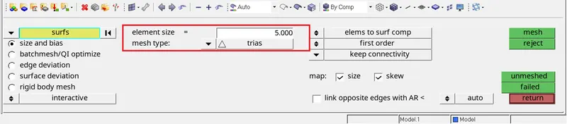
- Then the 2D mesh is converted to 3D mesh by switching to the 3D panel where the tetramesh option is selected and the elements displayed are selected and processed for tetrameshing. Thus the tetramesh is done and the 3D mesh is verified by masking few elements of the geometry.
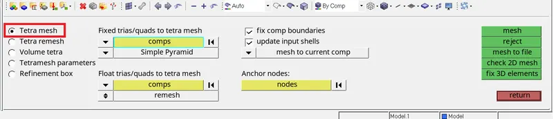
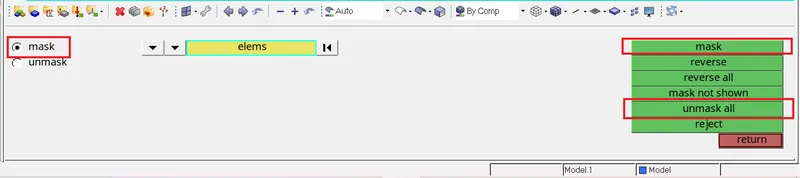
- Tetramesh can also be made by volume tetramesh method in which either the solids or surfaces of the component are selected and meshed. Thus the volume tetramesh is made but the quality of the mesh made by this method does not have better quality mesh as compared to the 2D to 3D mesh converting method.
- The other method for making tetramesh is by using the quick tetramesh from the utility panel and the mesh made in this method is almost similar to the mesh made by volume tetramesh.
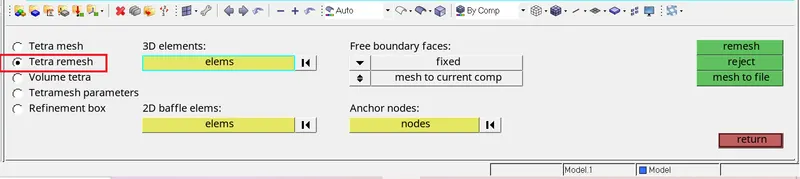
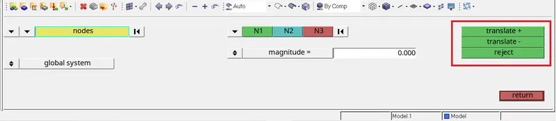
- The tetramesh is then checked for the tetcollapse using the check elements option and the failed elements are fixed up by using the tetraremesh option and still the elements which are failing for tetcollapse are fixed by using the translate option.
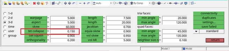
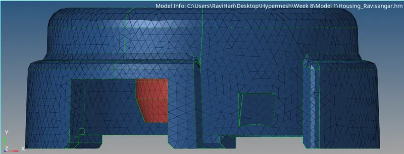
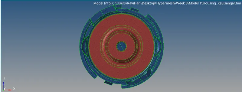
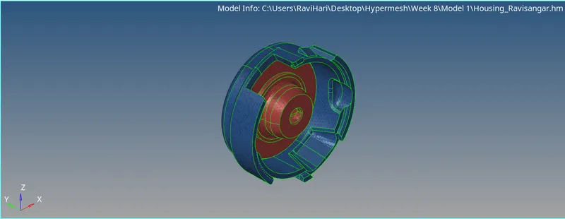
- Thus the tetramesh of given quality is made for the housing model by using the most suitable and accurate method.
CAD Model Images:
MODEL 2 - ARM BRACKET:
Steps to be followed:
- Import the given model using the Import Deck → Geometry → STEP type file → Browse and select the file → Click import.
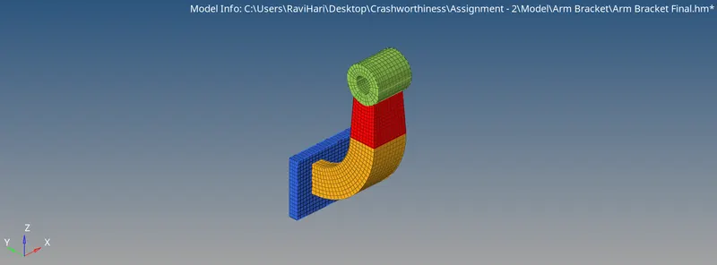
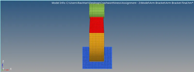
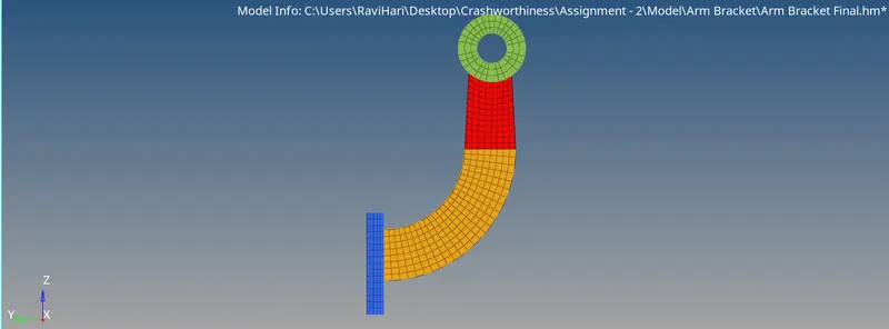
- Check for any solids in the imported model and if any are found they can be deleted using the delete option and the given model is made ready for meshing. The given model has 4 components namely Base, Arm Straight, Arm Curve & Boss.
- Geometry cleanup is carried out either by defeature option or by manual cleanup using toggle edge option. The model is thus made properly ready for the meshing.
- For meshing, the target element length given here is 10 and the meshing to be done for this model is Hexameshing. Thus the 2D mesh type followed for the surfaces is by quads only option in the automesh panel.

- Initially the base component is 2D meshed on one face alone and the mesh is converted to 3D hexamesh using the element offset option. In element offset panel the parameters such as elements to be offseted, Number of layers, Total thickness are assigned and clicking on offset, the 3D hexa elements are created for Base component.


- For arm curve the 3D mesh is made by using the spin option in the 3D panel. In order to spin the 2D elements, the elements that are on the base corresponding to the arm curve are selected and the spin option is processed and the value here for on spin is 25 and the angle in 90 degrees.

- For the direction of spinning the elements it is take along the x-axis and for the base node, centre node of the arm curve is created using the three nodes in the distance option. Thus on clicking spin option the 3D elements for arm curve is created.

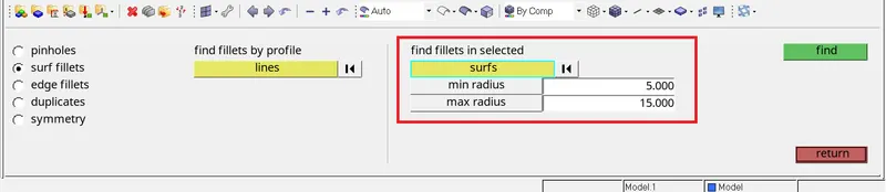
- Next for creating 3D elements in the arm straight, linear solid option in the 3D panel is used. As a function, the elements should be present in both the source and destination geometries. The faces are utilised in order for the source geometry to have 2D quad elements. This is done by selecting the Faces from the tool panel. After selecting the component, click "Find faces" as shown.

- The faces that are obtained will be displayed as shown below
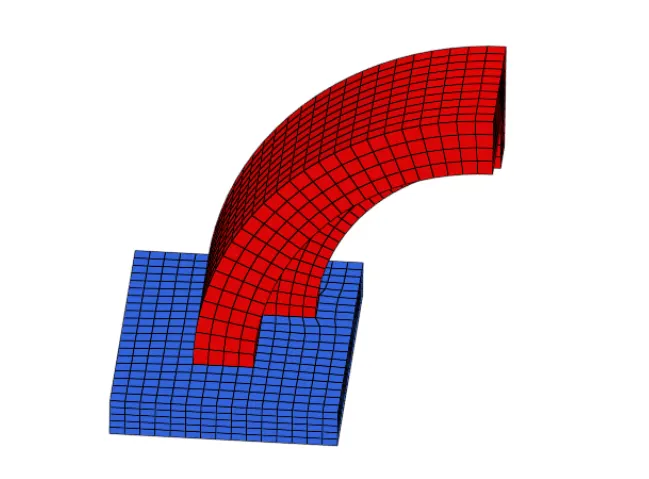
Then an equal number of 2D elements are created on the destination surface and thus the linear solid option can be peroformed.
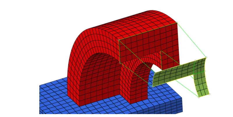

- For boss component, the 3D mesh is made by solid map option and for this purpose the elements to drag, along geometry and the destination geometry are to be selected. For the elements to drag, 2D elements are created on one of the surface and for along geometry using mixed option node path and the lines along which 3D mesh are to be created are selected and then the destination surface is the either side surface with 2D mesh.

- Finally the 2D elements that were created for 3D meshing is deleted and thus the 3D hexamesh is done for the Arm Bracket.
CAD Model Images:
CONCLUSION:
- Thus the required parameters using the given values are calculated and are provided as input in the cards for solving the model in Radioss Solver Deck successfully.
- Thus the Volume mesh is done for Housing using Tetramesg and Arm Bracket using Hexamesh is done successfully.