Assignment 2
Objective :-
- To find out speed of the sound wave in the steel material .
- To find out the time step in in the rail component of 1000mm length .
- To find out the time required by the sound wave to propagate through the rail .
- To Edit the engine file so that the stress wave can be monitored, moving from one end of the rail to the other during impact -this will require a termination time equal to the time it takes for the sound to travel the length of the rail(set on/RUN card).
- To Set the frequency of animation output to a time that will give 20 animation steps(/ANIM/DT).
- To Change /print -10.
- To mesh the models .
Procedure :-
1. Given Material properties of steel
* Density of steel (ρ) = 0.0078 Kg.mm^3
*Youngs modulus (E) = 210000 Mpa
we know that velocity of sound for 1D element is C=√E/ρ.
By substituting the above values in the equation .
C=`square root`210000/0.0078
C=5188.74 mm/ms
2. Given Length of the rail component (L) = 1000mm .
We know the speed of the sound wave through steel material (C) = 5188.74 mm/ms
Therefore Timestep (dt) = L/C
dt = 1000/5188.74
dt= 0.1927ms.
3.The time required for the sound to travel the rail is (T) = Length of the rail (L) / Speed of the sound (C) .
T=1000mm/5188.74mm/ms
therefore T= 0.1927ms .
4&5 . Termination time = Time taken by the sound wave to travel the rail .
= 0.1927ms
Frequency(F) = termination time/animation steps
F=0.1927/20
F=0.009635ms
F=0.000009635s
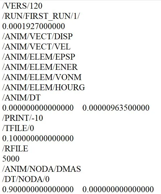
6.Change /print -10 is already mentioned properly in engine file.
7.Tera mesh :-
- Imported cad model image .
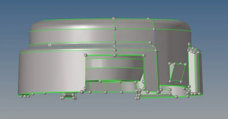
- We required a surface mesh for generating 3D elements .
- Go to automesh command (F12 is the shortcut key ) from 2D panel .
- Set the target element length and mesh type as trias .

- All the surfaces to be meshed .
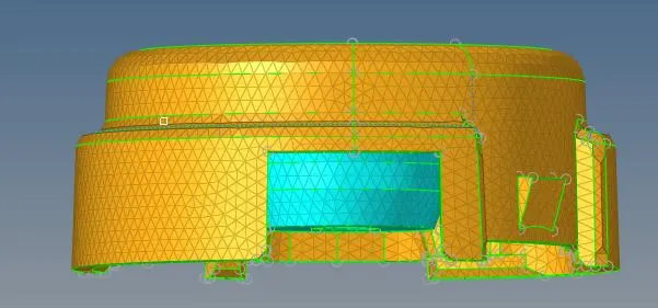
- Go to tetramesh command in 3D panel .
- Select the comps and click on mesh .
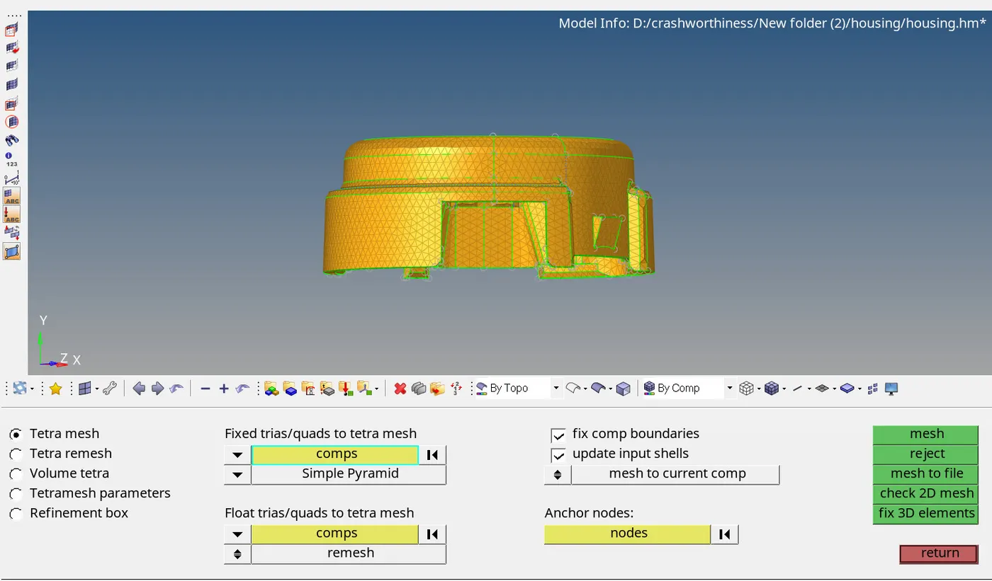
- 3D mesh will be generated .
- check for the quality .
Hexa mesh :-
- Imported Cad model image .
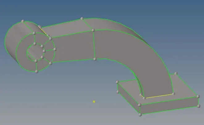
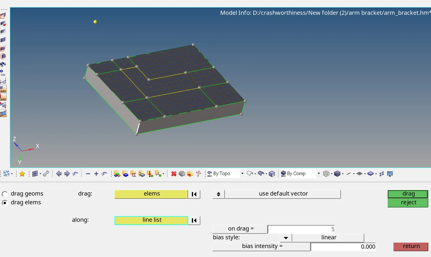
- Mesh the base surface and use the line drag option to generate a solid mesh .
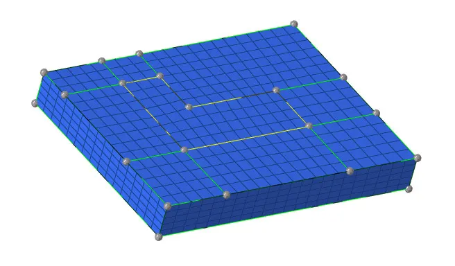
- Solid mesh will be created as shown .
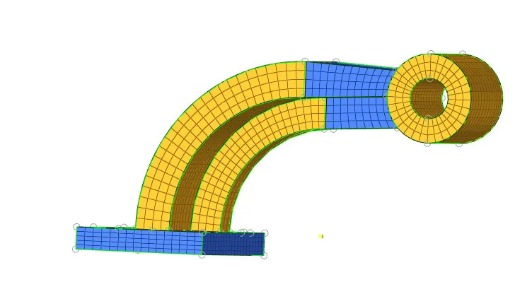
- similarly we can use spin option for arm curve .
- We can use solid map for the arm straight and bose .
- check for faces wether the conectivty is fine in the all componets or not .
Conclusions :-
From this challenge i have understood that how to do 3d meshng . How to calculate the time step for the 1D elements .