SIMULATING RAIL COMPONENT IN HYPERMESH WITH RADIOSS SOLVER
OBJECTIVE :
- To check the material properties of the rail component and calculate the speed of sound in steel rail
- To calculate the time takes for a shock wave to travel from one end of the rail to the other where length of the rail is about 1000 mm.
- To calculate Time for sound to travel length of rail
- Edit the engine file so that the stress wave can be monitored, moving from one end of the rail to the other during impact -this will require a termination time equal to the time it takes for the sound to travel the length of the rail(set on/RUN card)
- Set the frequency of animation output to a time that will give 20 animation steps(/ANIM/DT)
- 3d meshing tetra mesh and hex mesh on arm bracket and housing model.
THOERY :
- Radioss
Radioss is a solver created by Altair which is a powerful and robust solver used for solving explicit analysis.the processing of RADIOSS files can be used at users discretion.this solver follows two kinds of files i.e., starter and engine file.
starter file is essentially called as input deck.all the input details about model setup like components,mesh nodes/eleements information,material laws,contact details,boundary condition details etc.,
whereas engine file is a file which contains the running instructions for the solver.it also contains the animation outputs expected from the model.
- Time step
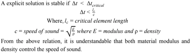
In the context of explicit analysis, time step is the time required for a shock wave to propagate across the smallest distance of the element. A run is a single model simulation and it starts at time zero and continues till the user defined endpoint is reached. The basic time unit in the run is the time step.
The time step is directly dependent on the length of the element and inversely proportional to the speed of sound of material.The speed of sound of the material is dependent on both material modulus and density of the material. So, if the material is stiffer (higher modulus of elasticity), the speed of sound increases resulting in a lower solution time step.
PROCEDURE :
Here in this model we have been given a steel rail component of length 1000 mm for which we have to calculate the speed of sound that travel throughout this rail length
After importing the rail component we will check its material properties to calculate the speed of sound in steel rail.to calculate the sopeed of sounf in steel rail we need density (rho) and youngs modulos E .that we can notify ubder material-steel. as shown below
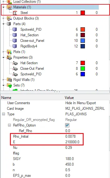
here we found that Rho-initial value ie., density value as 0.0078 and E value as 210000.0
- now we will calculate the speed of sound (C)
c =  = √(210000/0.0078)= 5188.745 mm/ms
- Since the length of the steel rail is already given i.e., 1000 mm we can calculate the time taken for the shockwave to travel from one end of the rail to other i.e.,
Elemental Time step, Δtc = (l/c)=(l/√(E/⍴))= Length of the rail / speed of sound = 1000/5188.745 = 0.1927ms
therefore,Time for sound to travel length of rail i.e., Δtc=0.1927
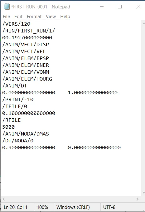
- we edited engine file so that the stress wave can be monitored, moving from one end of the rail to the other during impact -this will require a termination time equal to the time it takes for the sound to travel the length of the rail(set on/RUN card)
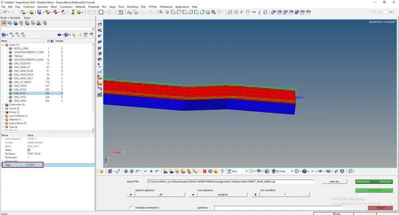
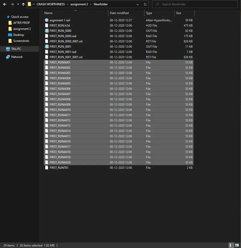
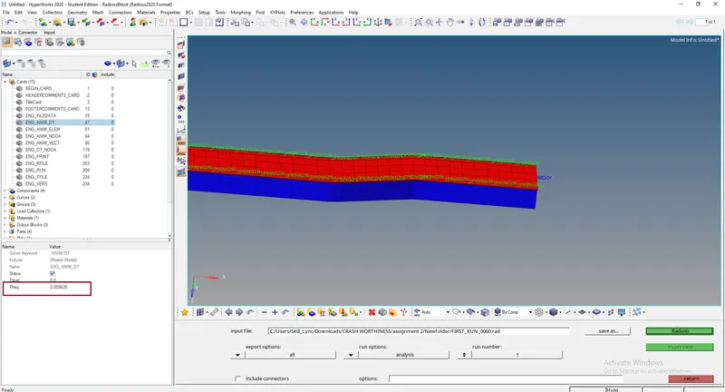
- Then we will Set the frequency of animation output to a time that will give 20 animation steps(/ANIM/DT)
Tfreq=Termination End time / Steps Required = 0.1927/20=0.009635
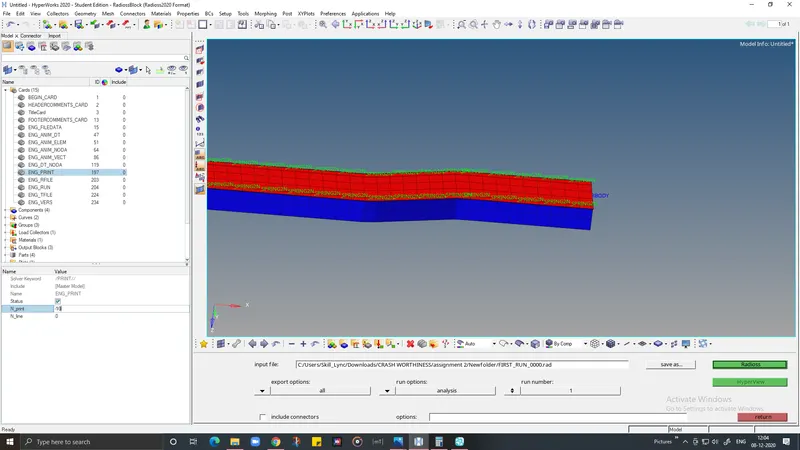
- Change /print -10.
to set value print -10 we need to go cards > ENG_PRINT
- 3d meshing tetra mesh and hex mesh on arm bracket and housing model.
- TETRAMESHING ON HOUSING MODEL
Firstly we will import the housing.since the model we have given is in .stp format
Files with the .step extension are usually 3D model files created in the STEP file format. STEP stands for Standard for the Exchange of Product Data. This ISO standard exchange format is used to distribute 3D data files (such as CAD files) in a format that can be viewed by a variety of software applications.
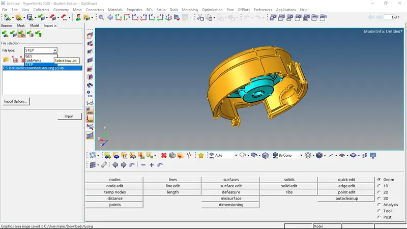
To import the model in hypermesh to import solver deck  and switch to import geometry
  and select the suitable file type from the given options and click on import.since housing is given in .stp file format so i chose STEP as my file type.
we continue with applying 2d mesh by selecting 2d-automesh-surfaces .then we have to select all the surfaces we want to apply mesh on.we can press F12 key as a shortcut to enter into meshing panel.
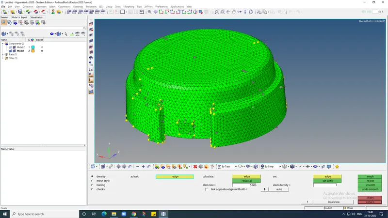
now the model is ready for tetra meshing.the process for tetra meshing is as follows.go to 3D-tetramesh,in the tetramesh panel select the elements under the "fixed tias/quads to tetra mesh" option.after selecting the elements click on the mesh button
once the meshing is finished .few elements are masked at random areas of the model to check the mesh generation.
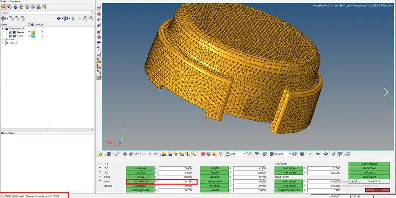
this method is how we convert 2d tria elements into tetrahedral elements using tetramesh panel.after completing the tetra mesh we check for failed elements by selecting tools-check elems-3D-tet collapse.
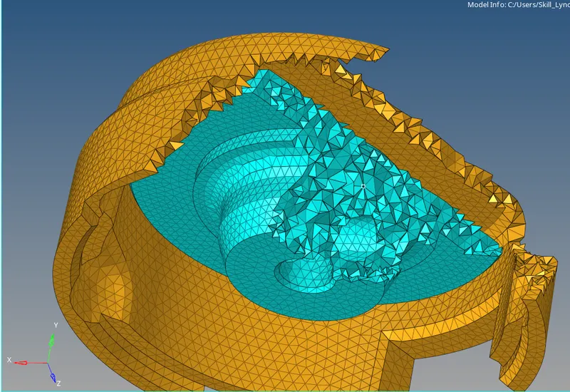
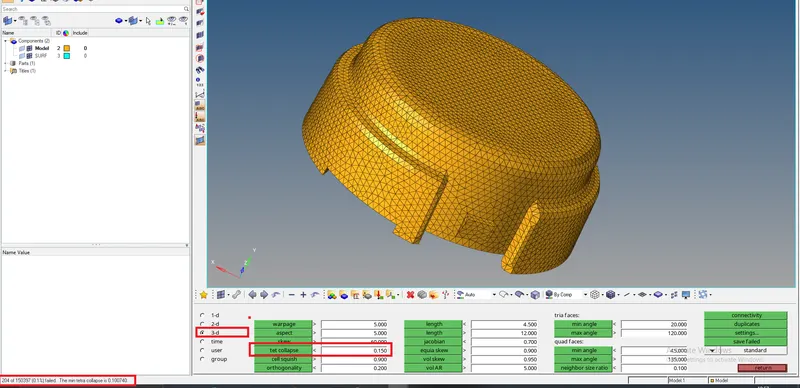
in the status bar it will show how many elements are present in the model.Click on the “save failed” option to save the tet collapse failed elements Isolate the failed elements, by clicking on “Mask” option Then right click on “elements”, to select the “retrieve” option.This will automatically select the failed elements as your masking entities.Click on the “mask” to hide the failed elements, then select the “reverse” option to show only the failed elements in the HyperMesh GUI
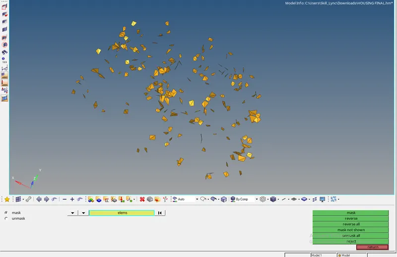
Now to clear the Tet collapse, select the Tools→ translate command. Manually inspect the failed element and do the following procedure:
-
Pick a node in any one failed element, which has minimum height.
-
Select N1, N2, N3 which represents the opposite plane of the prior selected node.
-
Choose the magnitude value approximately by trial and error method.
-
Click on the “translate” button to move the node
since there are so many failed elements clearing tet collpase for all elements take more time so we follow another method to clear the tetcollapse Using the “Tetra remesh” panel, to remesh failed elements. for that we go to the Tools→ tetramesh→ Tetramesh parameters, to specify the tet collapse value.Tick the checkbox of “Max tetra size” and “Min tetra size”, to specify the limit of tetra mesh size.Under “Elem quality target”, enter the target tet collapse value and tick the checkbox of fill voids, fix midnodes, smoothing
Once, after setting the “Tetramesh parameters”, select the “Tetra remesh” option.Select the “3D elements” and “2D baffle elems” for remeshing the model.Click on the “remesh” button, to clear the failed elements.
To ensure the Tet collapse quality, check the failed elements in the “check elems” option.In the status bar, now it will show the 0% failed elements as shown below:
2.3D HEXAMESHING ON ARM BRACKET MODEL
Right after importing the model. we can see that the solid part is splitted into 4 diff section. the base,curved section,tapered straight section and then the boss which are all connected together
first we have to make 2d mesh on the base surface with size 10, with only quad elemets.
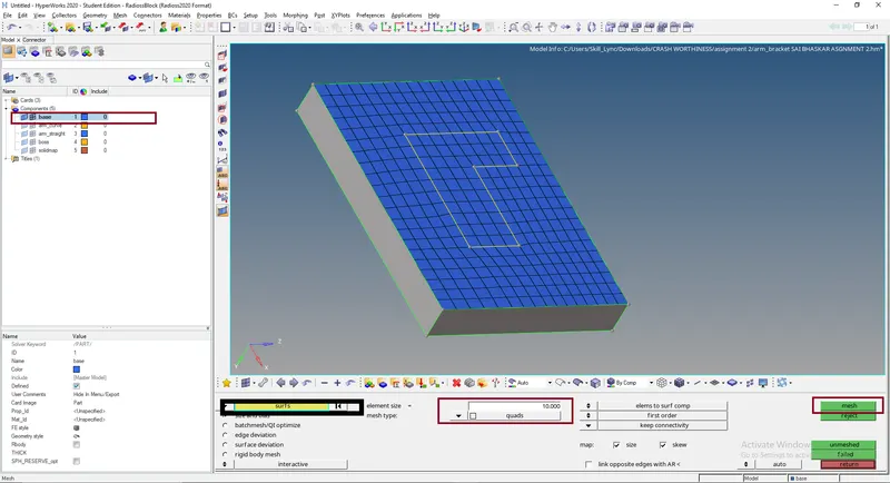
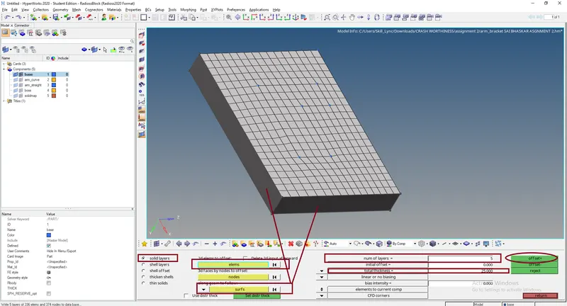
after meshing properly,we will go for solid mesh.to make solid hexa mesh from the shell mesh we created before we will use offset option that available under 3d panel.for that we go to 3d-element offset-solid layers then we select the shell elemets that we created before to offset then we select two adjacent surfaces just below that surface mesh on the base component in geometry to follow button.

later that we have to specify the no.of layer that mesh should be offsetted for that we will first measure thickness length of the base by pressing f4. we get 25 distance so we will choose 5 layers ie,. the height of element will be 5 with 5 rows of elements so that the thickness of 25 will be meshed properly.
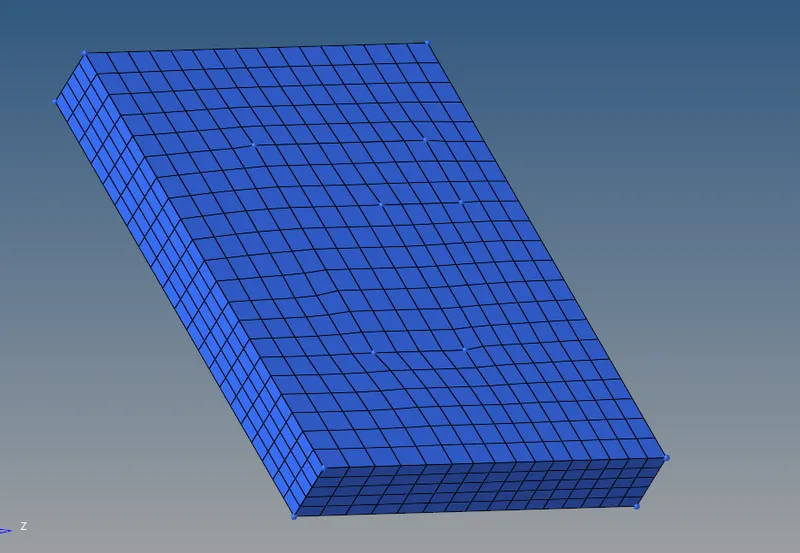
Now we will proceed meshing the with arm curve component.we will make sure that we hide all other solid elements by keeping only surface elements for that we will mask the elements (hex8) by config under mask tab.

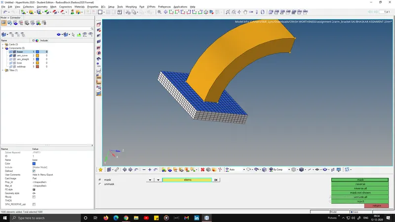
after masking all now we have are 2d shell elements.
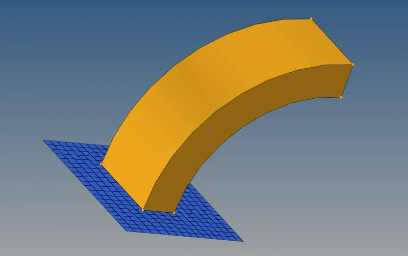
now we will switch on the arm curved component which have curved geometry,to mesh this type of geometry we will use spin elements option by choosing the elements at that particular cross-section where we have to spin the elements along the curved arm.
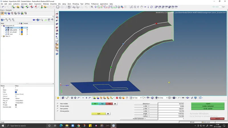
we need the centre point of circle to spin. For that we make a temp node in the centre by choosing F4 option by three nodes option then we select the node between which will create the circle centre node.
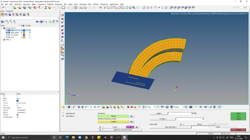
Then we select the elements and we will specify the angle of 90 degrees, and we choose x-axis to spin with the circle Center node as base point then we select spin- which will perfectly spin the elements along the curved arm.
Now all we have left are arm straight and boss .we will use linear solid option on arm straight since the geometry is linear. to create mesh we need 2d elements on one side of face tool-faces-select arm curve component so that we can get face elements on the surface so that we can make linear solid elements.
3d-linear solid. for linear solid we need source group and destination group .since we dont have destination element group, we will mesh the other wend surface of arm straight by matching the nodes on both sides.
After meshing we select the from and to source and destination elements. then for alignment we select the exact same equivalent nodes on both sides of surfaces and then by clicking on solids it will create linear solid elements.then will go to tools-faces and select the faces to delete after creating the hexa mesh on arm straight.
now we will mesh the boss. we will first mesh the upper surface of the geometry to use it as a source geometry.then we will slect (shift+f7) PROJECT option then we select surface nodes to project to the bottom surface,later we will go to 3D-SOLID MAP and then under source geometry we will select (none) and choose bottom surface as the destination geometry.after choosing the source and destination, we need the elements to drag to the bottom for that we will select the elements that we meshed before on the top surface then we will select mixed option under along geometry tab to select both node path and lines on ther boss and node path is the nodes that we have on the arm straight component and projected component.
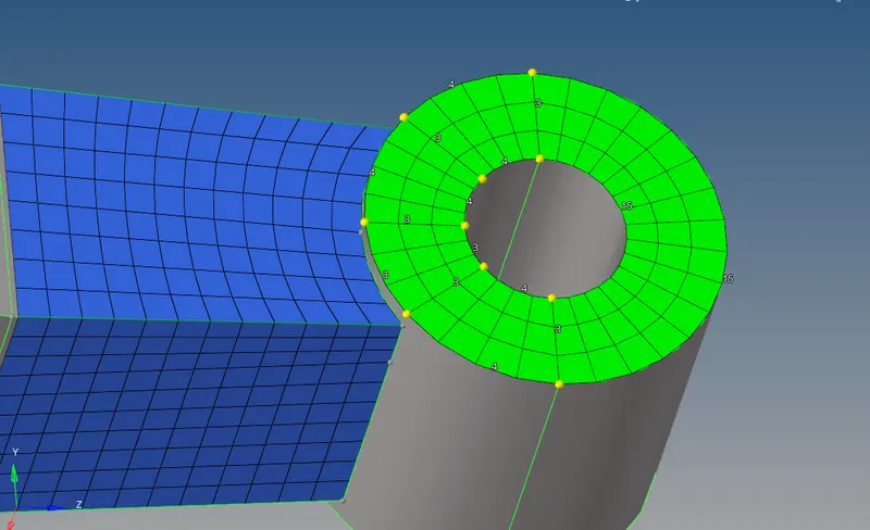
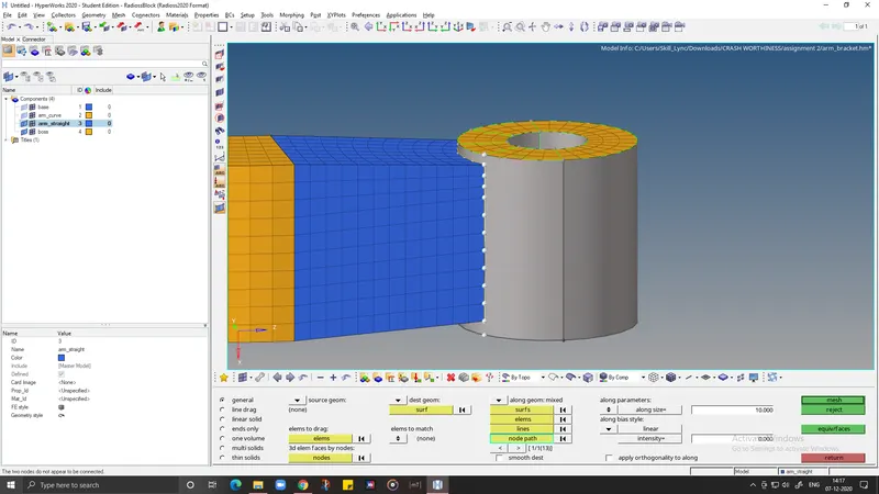
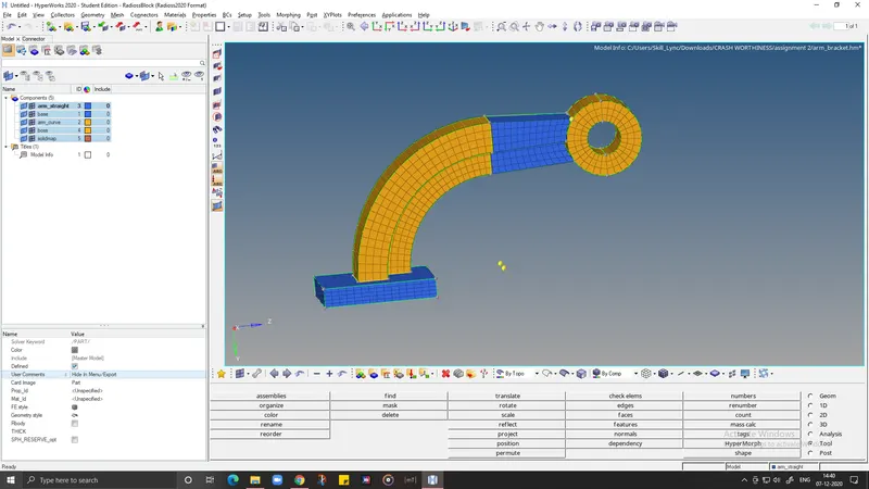
after meshing the boss component make sure that we delete that 2d shell elements ,so we go to delete option,then under elements we will choose elements by config ie., quad 4 elements and delete the shell elements on the top surface.now the component is free of shell elements and the meshing of part is completely done successfully without any errors.
RESULT
- calculated the time that takes for a shock wave to travel from one end of the rail to the other where length of the rail is about 1000 mm.
- calculated the Time for sound to travel length of rail
- Edited the engine file so that the stress wave can be monitored,
- calculated the value and edited the Tfreq value for frequency of animation output to a time that will give 20 animation steps(/ANIM/DT)
- Successfully 3d meshing tetra mesh and hex mesh on arm bracket and housing model has been done without elemental errors.