Assignment 2
AIM:
To process the 2D 1D and 3D mesh on the given model and understand the meshing concept strongly
Procedure:
2D Meshing of ARM BRACKET:
STEP 1) Check for the solids in the model, if any delete the same using delete option.
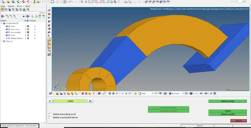
Figure 1. SOLID DELETION RPRESENTATION
STEP 2) The next step is to generate midsurface for the model. Use Geom > midsurface option.

Figure 2. Geom PANEL RPRESENTATION
STEP 3) Select and right click the surfs option and select displayed option to select the entire surface at one shot.


Figure 3. MIDSURFACE PANEL RPRESENTATION Figure 4. AFTER RIGHT CLICKING ON SURFS OPTION
The below image represents the midsurface generated.
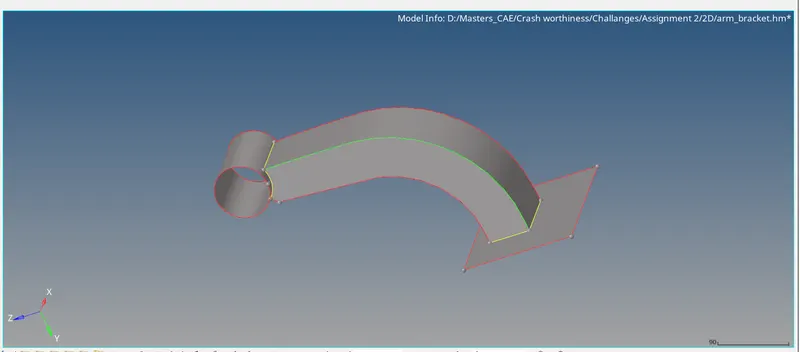
Figure 5. MIDSURFACE GENERATED
STEP 4) After craeting midsurface next is to start meshing with shell elements of size 5mm. Use 2D > automesh or F12 button.

Figure 6. 2D PANEL REPRESENTATION
STEP 7) To give quality criteria use Preferences > Criteria file settings and input the given criteria.
Min & Max : 3.5 & 7 mm respectively
Min & Max tria angle : 20 to 120
Min & Max quad angle : 40 to 140
Aspect ratio : 5
Warpage : 15
Jacobian : 0.5
Skewness : 60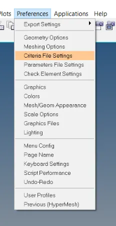
Figure 7. CRITERIA FILE SETTING
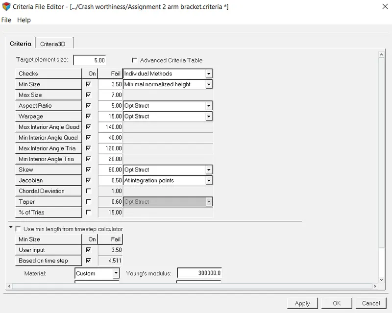
FIGURE 8. QUALITY CRITERIA
STEP 8) Mesh the model surface by surface so that we can have a cotrol over the quality criteria. Choose Target element size as 5mm.
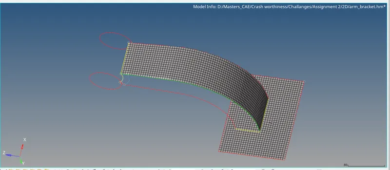
FIGURE 9. MESHING REPRESENTATION
STEP 9) After meshinfg the entire arm bracket, next is to check and fix for quality.
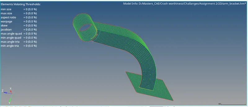
FIGURE 10. QUALITY CRITERIA
STEP 10) The next is to assign the elements their thickness, taken from the parent geometry. Right click on the tool bar and create property to assign appropriate thickness.
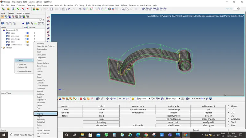
FIGURE 11. PROPERTY ASSIGNATION REPRESENTATION
STEP 10) Update the card image to PSHELL since they are 2D elements & and give appropriate thickness ( taken from parent geometry).
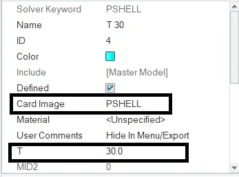
FIGURE 12. THICKNESS ASSIGNATION REPRESENTATION
Detailled representation of thickness assigned for 2D elements.
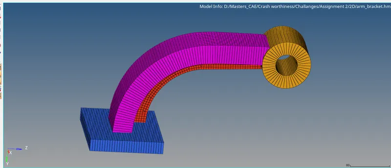
FIGURE 12. 2D DETAILED ELEMENT REPRESENTATION
3D Meshing of Arm bracket:
STEP1) Check for the solid and mesh the base part of arm bracket on bottom side.
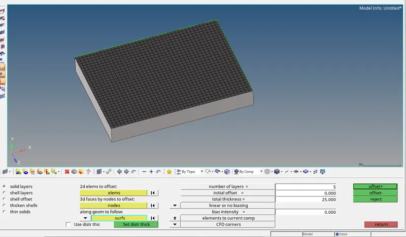
FIGURE 13. 2D REPRESENTATION OF BASE OF ARM BRACKET
STEP 2) Use 3D > Elem offset to convert the base model 2D elements.

FIGURE 14. 3D PANEL REPRESENTATION
STEP 3) Select the 2D elems to get offsetted and also select the surface along which the elements need to be offsetted(along geom to follow). Tabulate the value for number of layers and thickness in the tab provided & simply hit offset -.
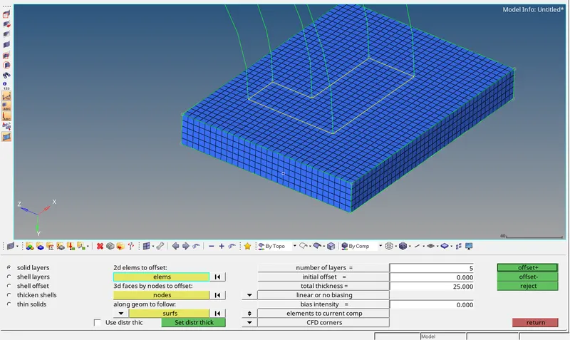
FIGURE 15. ELEM OFFSET REPRESENTATION
STEP 4) Mask the created hexa element and procees for next component arm curve. For this use by config option.
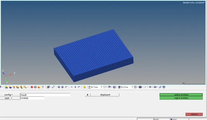
FIGURE 16. MASK OF HEXA ELEMENT REPRESENTATION
STEP 5) Find the center point of the arm curve. For this open distance option & select randomly three points on the curve and simply select circle center.
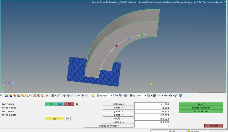
FIGURE 17. CENTER POINT REPRESENTATION
STEP 6) select the particular elements to spin, choose accurate axis & specify the base node, record the angle and on spin value as shown and hit spin+ or spin - according to the necessary direction.
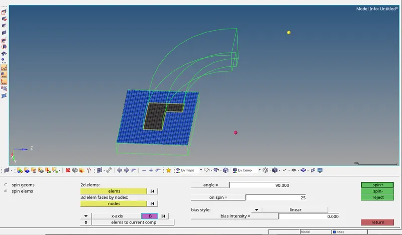
FIGURE 18. SPIN PANEL REPRESENTATION
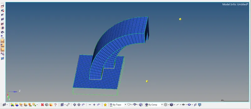
FIGURE 19. AFTER SPIN REPRESENTATION
STEP 7) Use Tool > faces to find the face of arm curve so that we can start by keeping the face of arm curve as base for 3D meshing of arm staright. Also mesh the smaller side of arm straight (Blue meshed part). Make sure all the elem number are same on the face and the meshed part.
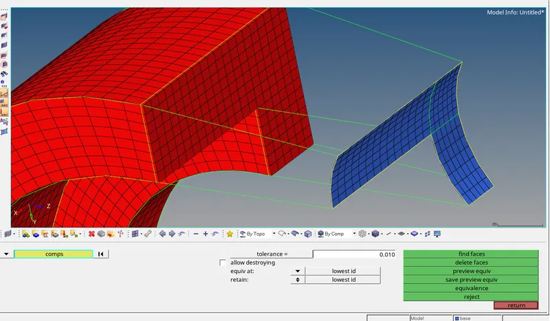
FIGURE 20. TOOL PANEL REPRESENTATION
STEP 8) Selct the face elements for from elems and created mesh elems for to elems . Select the alignment nodes as selected and give density value and hit solids option.
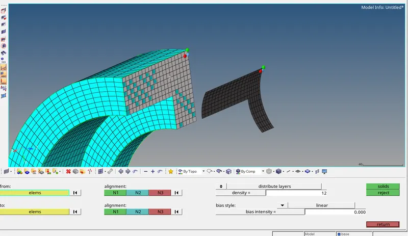
FIGURE 21. LINEAR SOLIDS PANEL REPRESENTATION
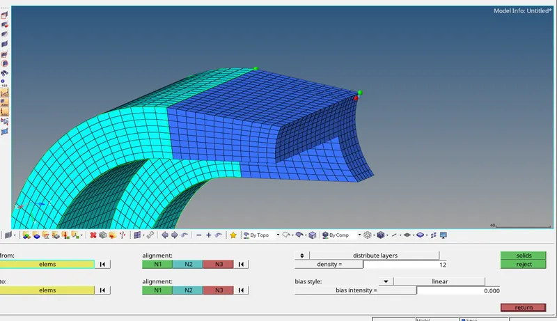
FIGURE 22. AFTER TOOL SOLID REPRESENTATION
STEP 9) Mesh one side of the boss part.
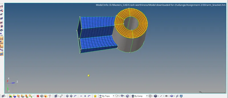
FIGURE 23. MESH OF BOSS REPRESENTATION
STEP 10) Project the node from the meshed element to the surface using Tool > project, to surface option. This is used for the correct alignment of the mesh.
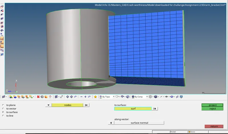
FIGURE 24. PROJECT PANEL REPRESENTATION
STEP 11) Select the elements to drag from the mesh of the boss, from along geom select mixed option & select the lines and the node path as in the image and simply hit mesh button.
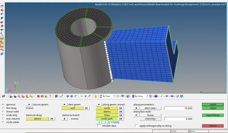
FIGURE 25. SOLID MAP PANEL REPRESENTATION
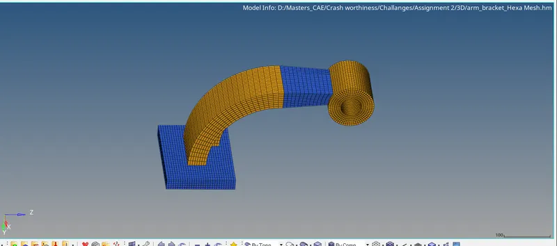
FIGURE 26. HEXA MESH REPRESENTATION OF ARM BRACKET
TETRA MESH OF HOUSING:
STEP 1) Mesh the cover of housing with trias mesh type and of element size 5 mm.
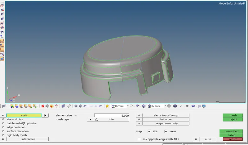
FIGURE 27. HEXA MESH REPRESENTATION OF ARM BRACKET
STEP 2) From tetra mesh parameters change the tet collapse value to 0.15 for quaity
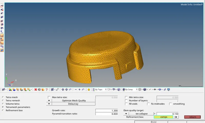
FIGURE 28. TETRA MESH PARAMETER REPRESENTATION
STEP 3) Go to Tetra mesh, select the elements and simple hit mesh button.
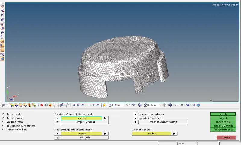
FIGURE 29. TETRA MESH REPRESENTATION
STEP 4) Similarly repeat the same steps for the cap of housing.
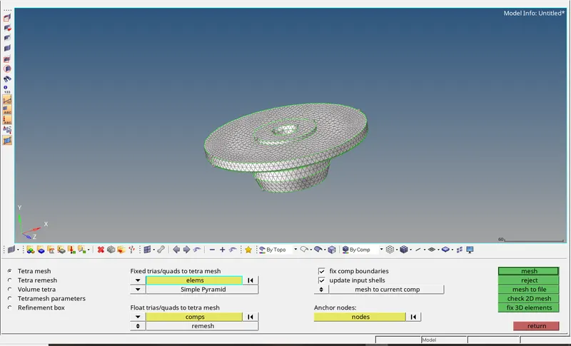
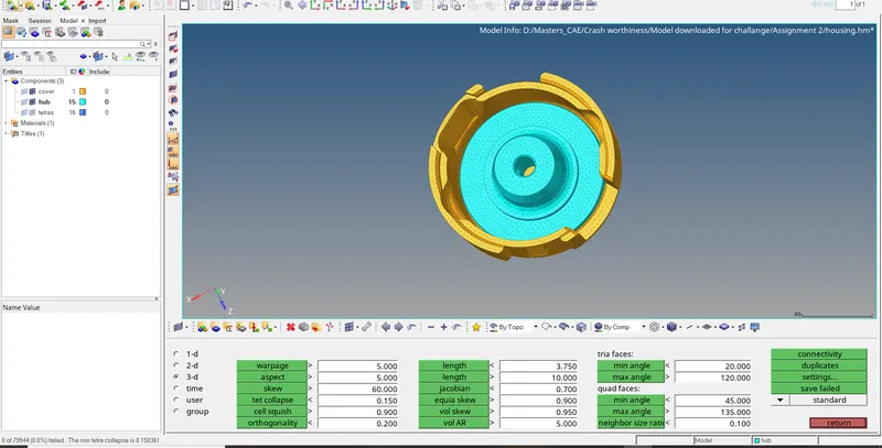
STEP 5) Finally check for tet collapse of the model using Tool > check elems or F10 button.
1D MESHING:
STEP 1) : Select the two surface and mesh them with the element size 5mm.
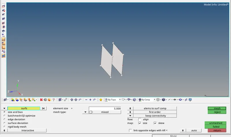
FIGURE 32. MESH PANEL REPRESENTATION FOR 1D ELEMENT
STEP 2) From 1D > Springs, create a simple spring connector as shown. Select the two nodes between which the spring has to be placed
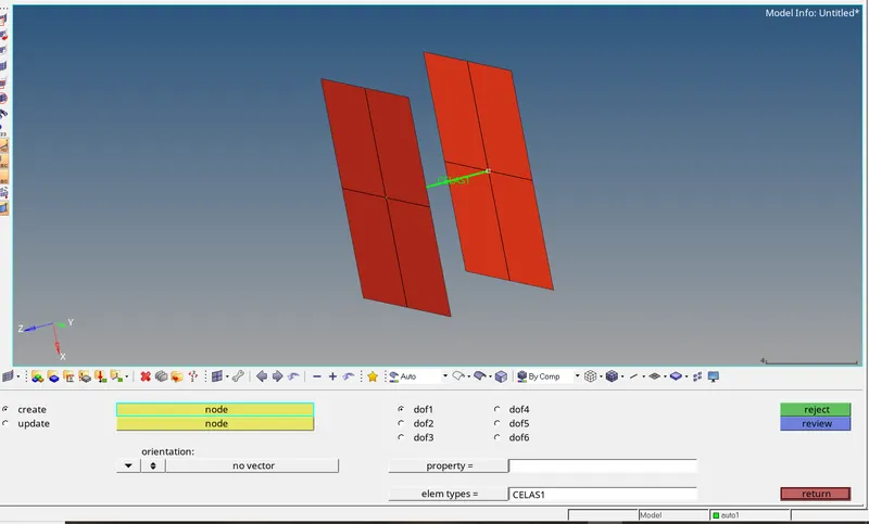
STEP 3) Update them with single dof, by using update option.
Questions: