Assignment 1-2D Meshing Challenge
Objective :
To Carry out the geometry cleanup operation on the given 3 files.
- Practice
- Clip Repair
- Mounting Bracket
There should not be any free edges, convert all of them into refine geometry.
- Clean the geometry.
- Extract midsurface.
- Clean midsurface geometry.
- Ignore holes less than dia 5mm.
- Create 2D mesh with target length 5mm, min 3.5mm max 7mm.
- And assign proper thickness, by creating a generic property.
- Then Save in .hm format.
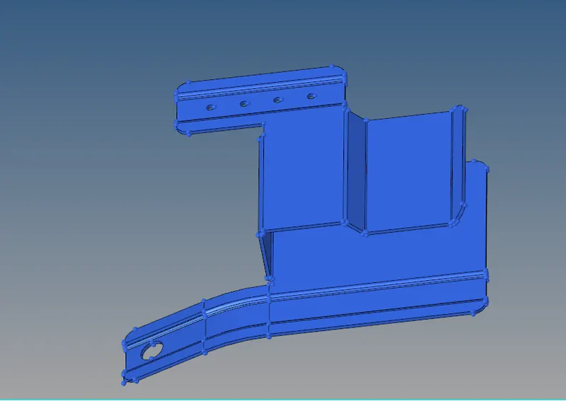
Fig 1 Model-1 Practice
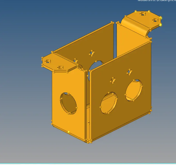
Fig 2 Model-2 Clip repair
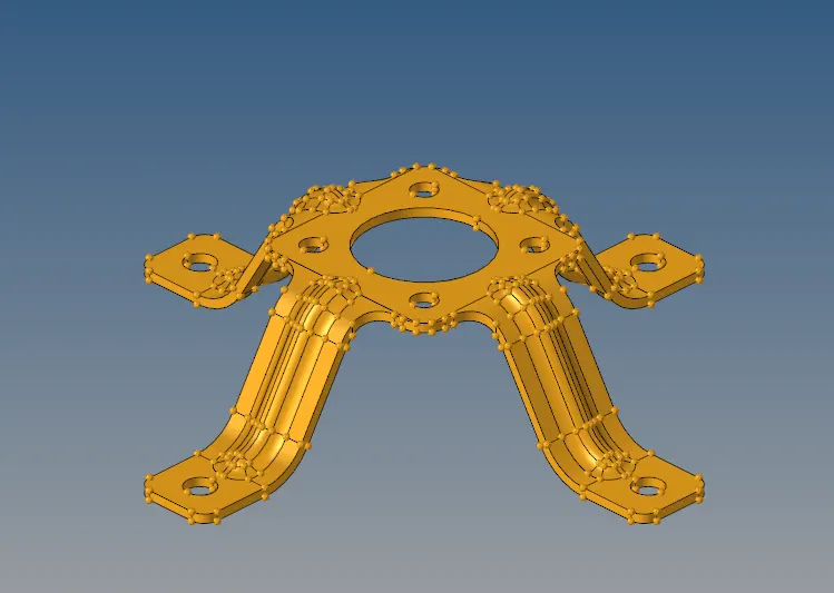
Fig 3 Model-3 Mounting bracket
Procedure:
Part-1
1. Cleaning the Geometry:
The Geometry in the Topology mode should be checked for free edges.
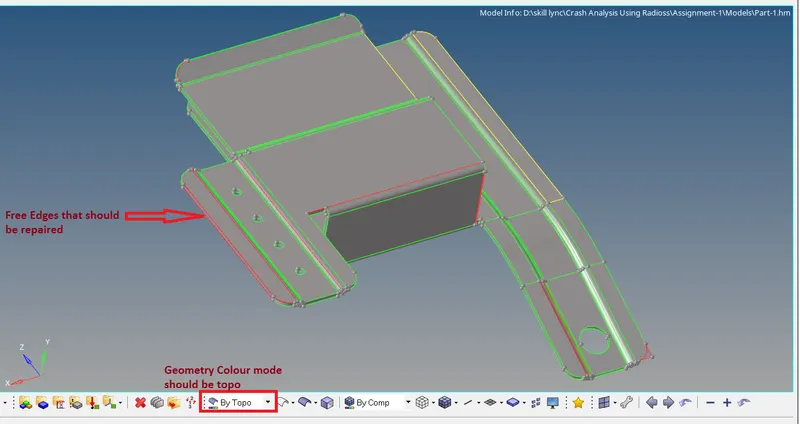
Fig 4 Part Geometry to be cleaned up
These Edges are toggled using the Quick edit option and the freed edges are toggled to split surface edges.
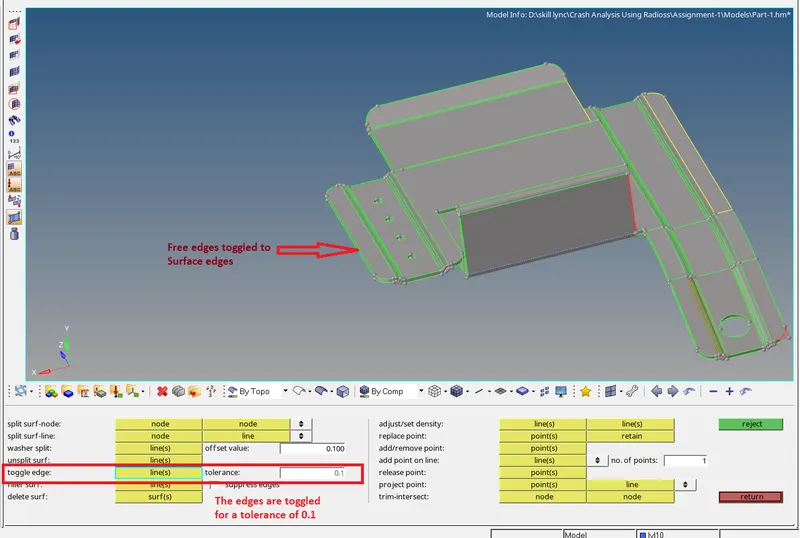
Fig 5 Free edges toggled to Surface edges
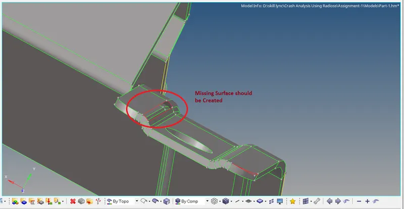
Fig 6 Part geometry with missing surface
The Missing surfaces are created using the Create surface using lines option from the surface tools in the geometric tools panel.
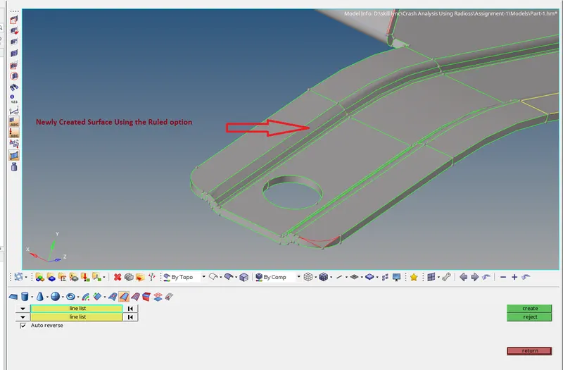
Fig 7 Creating the surface Using the Surface edges through the ruled option.
2. Extracting the Mid- surface:
The Mid-surface for the given geometry is extracted using the mid-surface tool in the geometric tools panel.
In the Extraction Option Sub panel the option, the option chosen is offset+planes+sweeps.
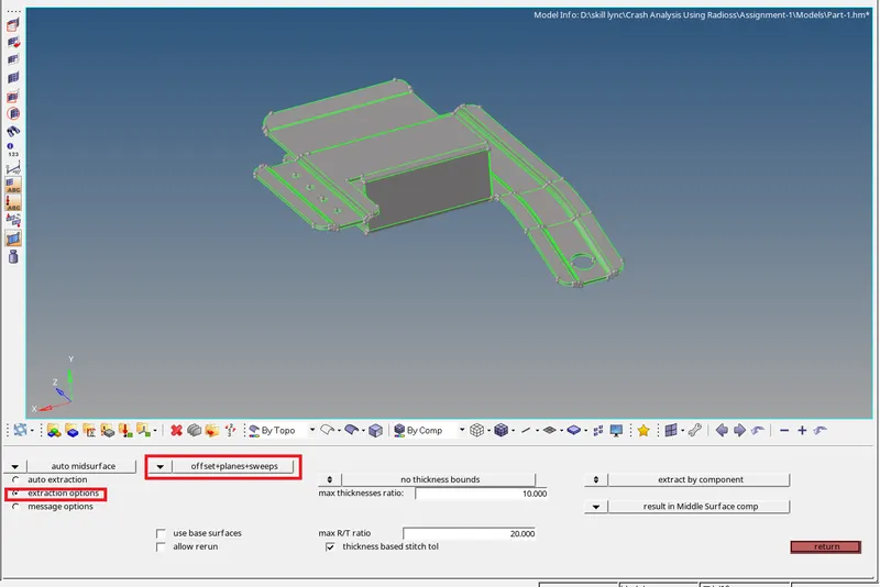
Fig 8 Extraction option Subpanel
The Mid-surface to be extracted is chosen & the extract button is hit.
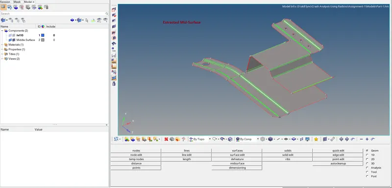
Fig 10 Extracted mid-Surface
3. Geometric Clean up of Extracted Mid-Surface
The Extracted Mid-Surface has anamolies such as surface holes which are less than 5 mm,Surface fillets less than the radius 3.5mm & free edges. Hence these Geometric anamolies have to be cleaned up using the Quick edit option and defeature option.
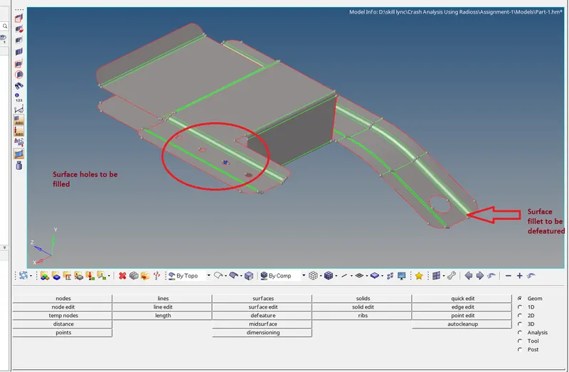
Fig 11 Mid surface to be cleaned geometrically
The holes on the surface are filled using the filler surface tool in the Quick edit tools panel
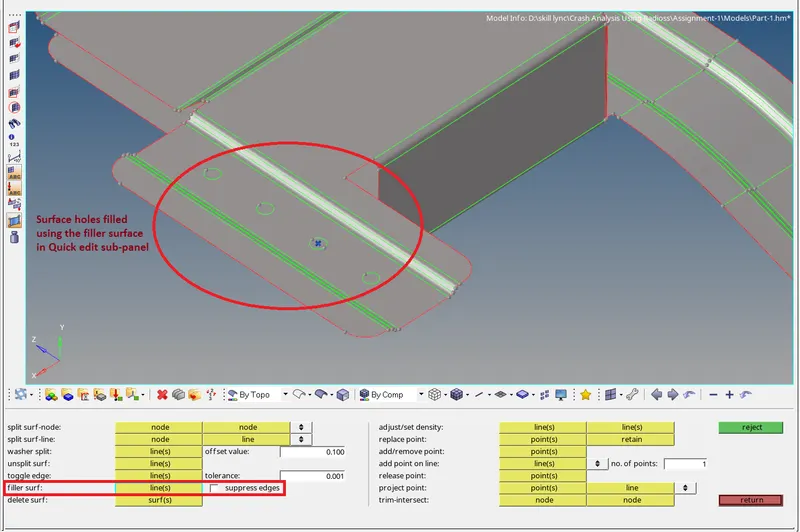
Fig 12 Filling Surface hole using quick edit tool
The Surface & edge fillets are defeatured through the Defeature tool in the Geometric tools panel.
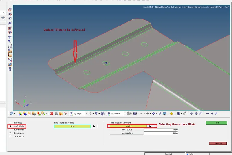
Fig 13 Surface fillets to be defeatured
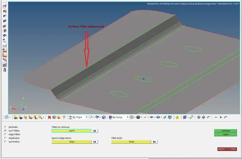
Fig 14 Surface fillet defeatured
Similarily the edge fillets should be defeatured using the defeatured command in the geometric tools panel.
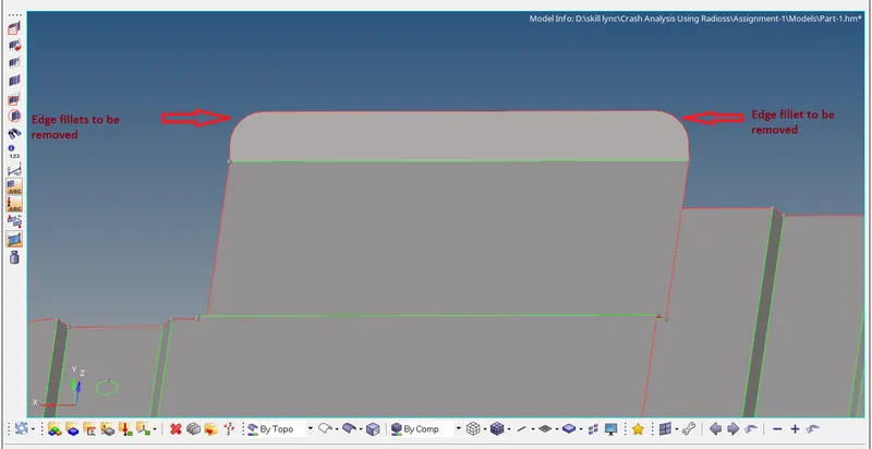
Fig 15 Edge fillets to be removed
The Minimum radius , maximum radius & the Minimum angle of the radius of the edge fillet for the identification of the edge fillet in the surface is entered in the edge fillet subpanel of the defeatured tools command. Then the surface is selected along with the one of the edge fillet and the find button is hit. The edge fillets in the surface are identified on the screen and then the remove button is hit which removes the edge fillets on the that surface.
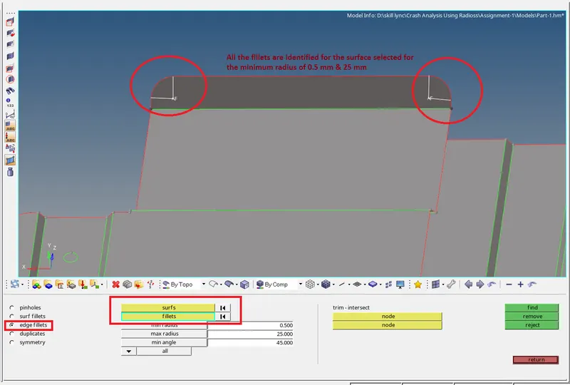
Fig 16 Defeaturing of the edge fillets
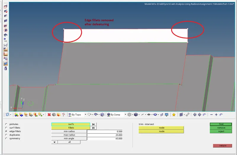
Fig 17 Edge fillets removed after defeaturing
All the Free edges in the mid surface are toggled to convert it in to surface edges using the toggle option in the Quick edit sub panel.
4. Creating 2d mesh on the Extracted Mid-surface:
The Surface for which the meshing is to be carried out is meshed using the automesh(F12) tool on the 2-d tools panel.
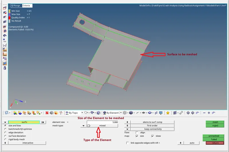
Fig 18 Surface to be meshed
The Element type chosen is Mixed & Size of the element is entered as 5 mm in the Auto-Mesh subpanel. The surface to be meshed is selected & the mesh button is hit to mesh that surface.
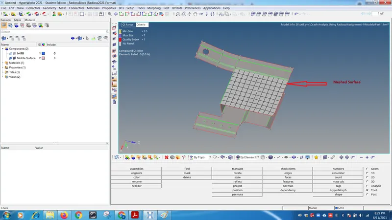
Fig 19 After the creation of the 2-d Mesh
5.Checking for the Element Connectivity between the elements of the adjacent Surfaces
The Connectivity between the elements of the adjacent surfaces are checked using the Edges option(Shift+F9) in the tools panel.
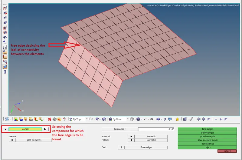
Fig 20 Checking for the element connectivity
The Preview equivalence for a given tolerance of 1mm is found and the elements are equivalenced to form element connectivity.
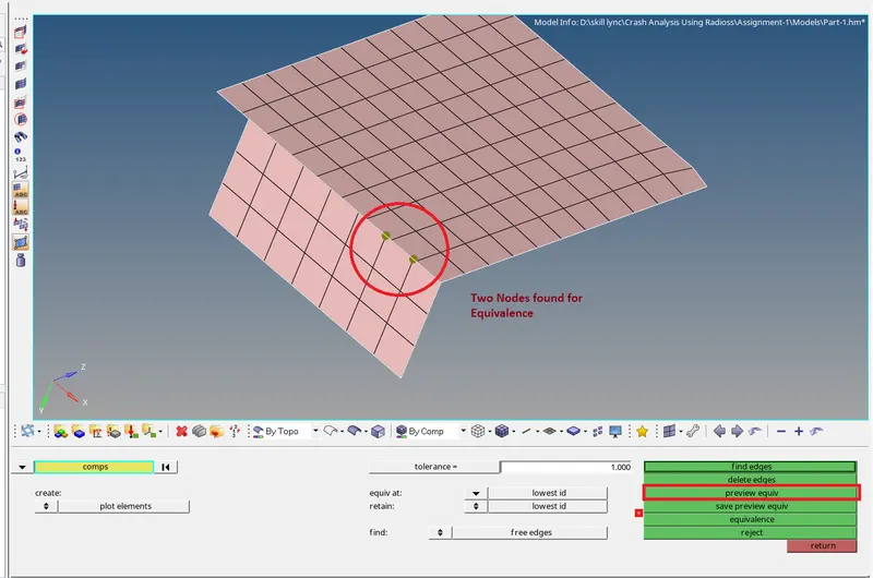
Fig 21 preview equivalence
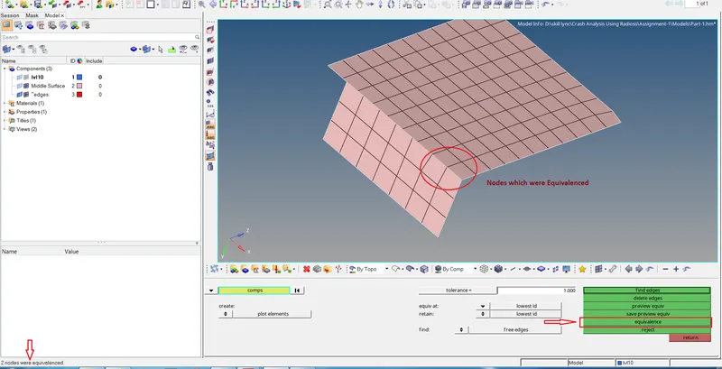
Fig 22 Nodes equivalenced
For those elements in which the nodes couldn't be equivalenced, the element connectivity is ensured by using the repalce node option (F3) in the 2d-tools panel.
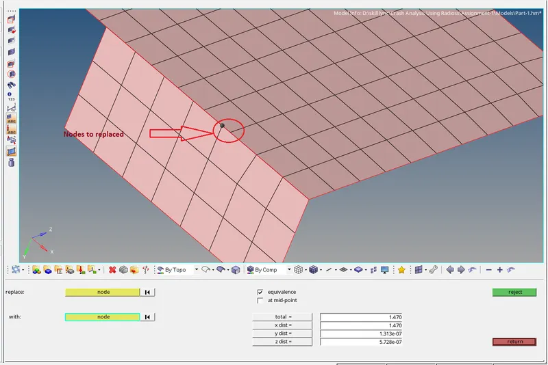
Fig 23 Before the replacing of the nodes
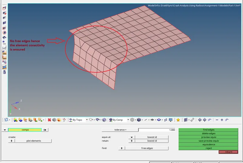
Fig 24 After the replacing of the nodes
6. Element Clean up :
The element clean up is done to ensure that all the elements fall with in the given Quality criteria i.e Minimum size =3.5 mm & Maximuum size = 7mm.
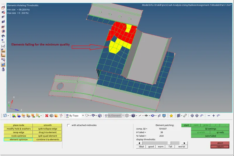
Fig 25 Before the element Clean up
The element clean up is carried out Using the clean up tool in the Quality Index or through various other methods depending upon the Quality criteria for which the element is failing.
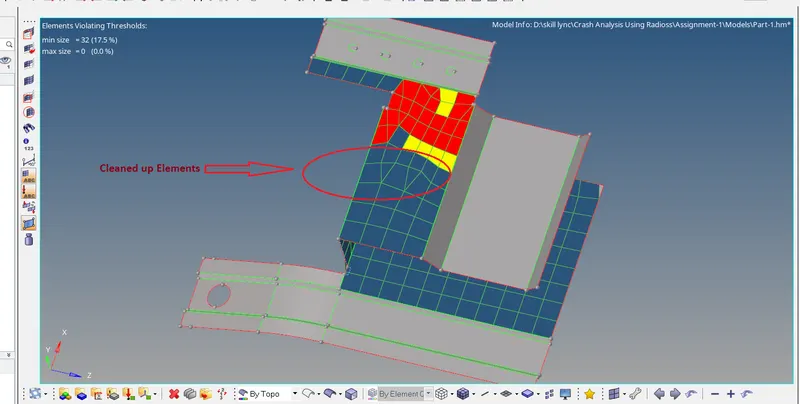
Fig 26 Cleaned Elements
7. Creating the Property to assign thickness
The Property is created in the Feature tree and the Thickness is entered the Property created.
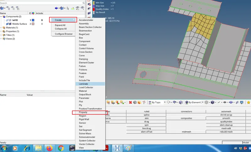
Fig 27 Creating the Property in the feature tree
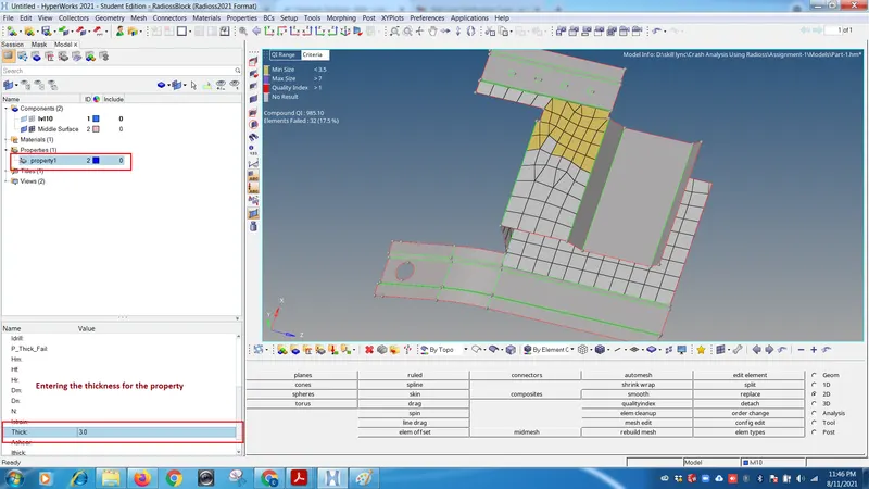
Fig 28 Entering the thickness for the property
The property with the thickness is assigned to the component in the feature tree in order to assign the thickness to the component.
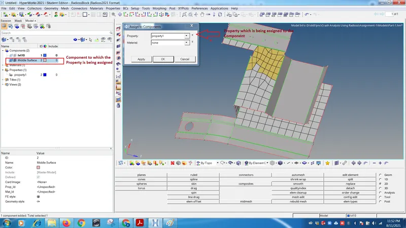
Fig 29 Assigning Property to the Mid-surface component
Result:
1. The Geometry of the given models were cleaned Successfully.
2. The Mid-Surface Extraction was carried out Successfully.
3. The Extracted mid-surface Geometry was carried out successfully.
4. The 2d- Mesh with target length 5mm, minimum lenght of 3.5mm and maximum length of 7mm were successfully created.
5. The Thickness to the shell elements was assigned successfully by creating a generic property
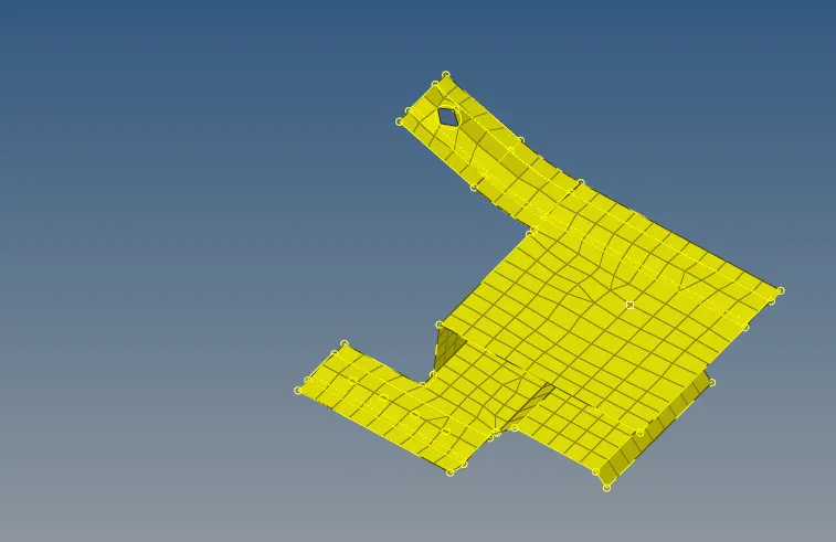
Fig 30 Completed Model1
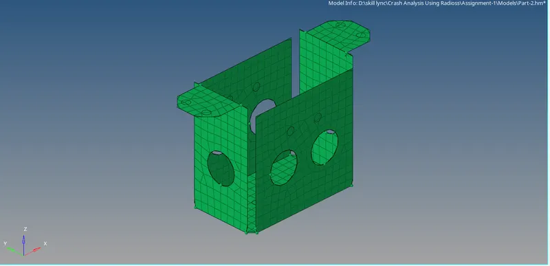
Fig 31 Completed Model-2
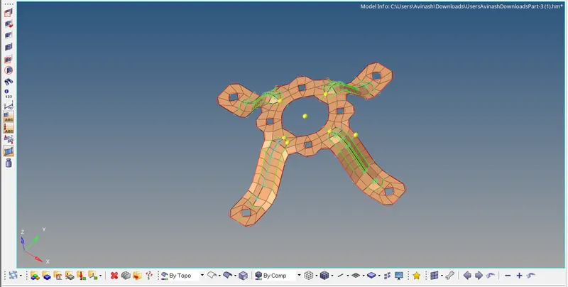
Fig 32 Completed Model-3