Assignment 1-2D Meshing Challenge
Report on 2D Meshing.
Objective-
Meshing of given CAD Models and achieve stated Quality criteria using Hypermesh (Radioss).
1. Part-1
CAD Model Image-
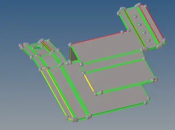
Fig.-1
Procedure-
1. Import the provided CAD Model and analyze it properly. If there exist any problem in model through Quick Edit & surface edit panel, rectify the problem as shown in fig. 2.

Fig.-2
2. Now proceed for mid-surface extraction. Fig. 3 Shows the extracted mid surface.
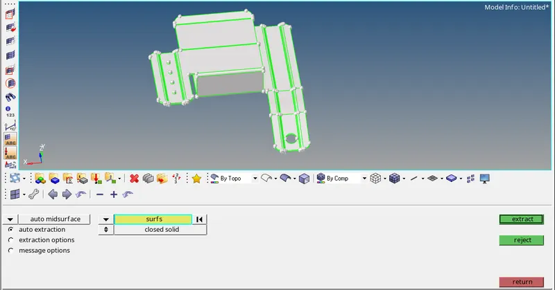
Fig.-3
3. Now, analyze the mid-surface properly, if any surface or edge is missing fix it and proceed for meshing.
4. Now go to the automesh and enter the element size as 5 and start meshing as shown in fig. 4. 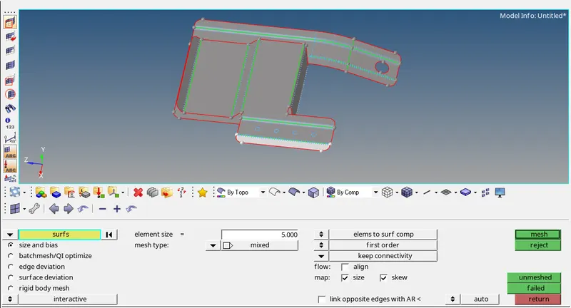
Fig.-4
5. Now, through preferences tab set the mesh criteria mentioned in the challenge as shown in fig. 5.
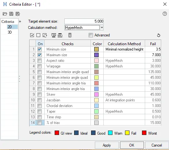
Fig.-5
6. Now, mesh the object. To maintain the proper mesh flow lines use the option Rebuild mesh. During meshing also pay attention towards element connectivity. If elements are connected properly using equivalence proper connectivity can be achieved.
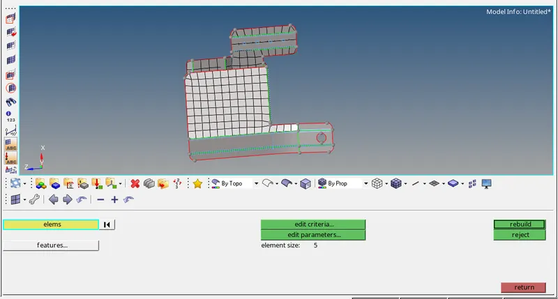
Fig.-6
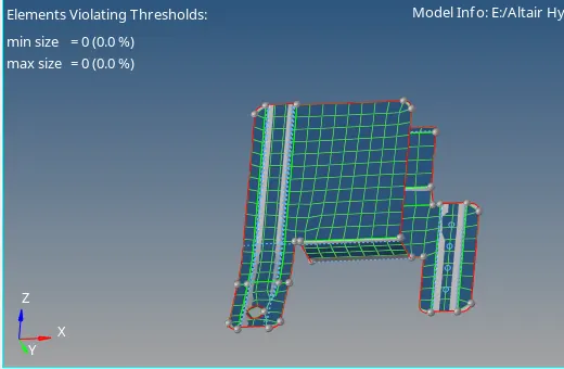
Fig.-7
7. Now, assign the material to the model as shown in fig. 8.
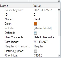
Fig.-8
8. Now create & assign the thickness as shown in fig. 9.
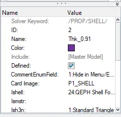
Fig.-9
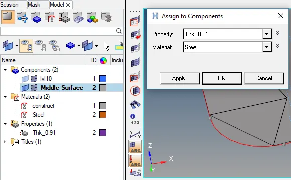
Fig.-10
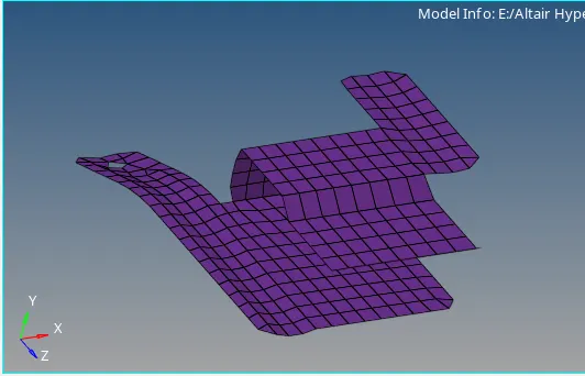
Fig.-11
2. Clip
CAD Model Image-
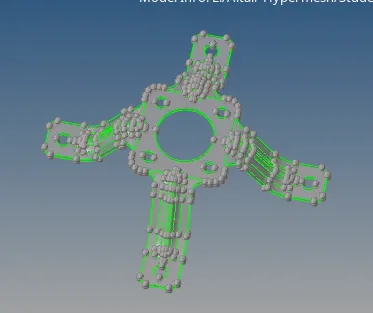
Fig.-12
Procedure-
1. Import the provided CAD Model and analyze it properly. If there exist any problem in model through Quick Edit & surface edit panel, rectify the problem as shown in fig. 13.
Fig.-13
2. Now proceed for mid-surface extraction. Fig. 14 Shows the extracted mid surface.
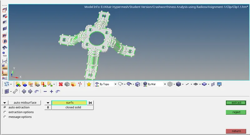
Fig.-14
3. Now, analyze the mid-surface properly, if any surface or edge is missing fix it and proceed for meshing.
4. Now go to the automesh and enter the element size as 5 and start meshing as shown in fig. 15. 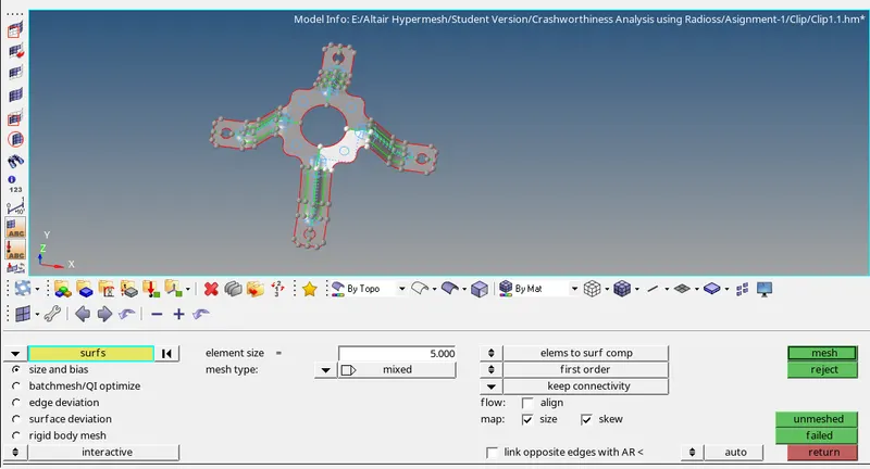
Fig.-15
5. Now, through preferences tab set the mesh criteria mentioned in the challenge as shown in fig. 16.
Fig.-16
6. Now, mesh the object. To maintain the proper mesh flow lines use the option Rebuild mesh. During meshing also pay attention towards element connectivity. If elements are connected properly using equivalence proper connectivity can be achieved. Here use the rotate & reflect option to create the mesh.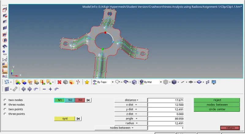
Fig.-17
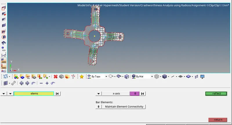
Fig.-18
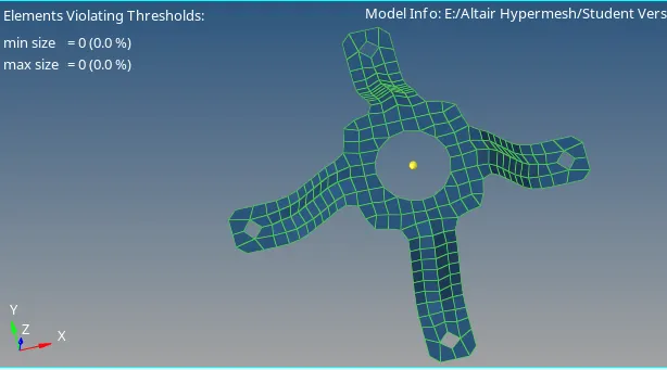
Fig.-19
7. Now, assign the material to the model as shown in fig. 20.
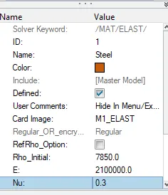
Fig.-20
8. Now create & assign the thickness as shown in fig. 21.
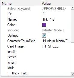
Fig.-22
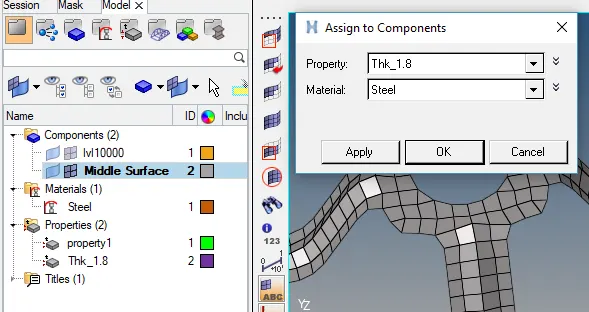
Fig.-23
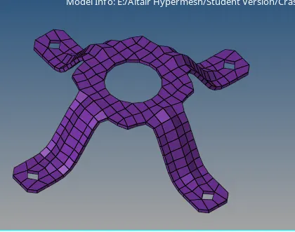
Fig.-24
3. Mounting Bracket
CAD Model Image-
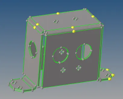
Fig.-25
Procedure-
1. Import the provided CAD Model and analyze it properly. If there exist any problem in model through Quick Edit & surface edit panel, rectify the problem as shown in fig. 26.
Fig.-26
2. Now proceed for mid-surface extraction. Fig. 27 Shows the extracted mid surface.
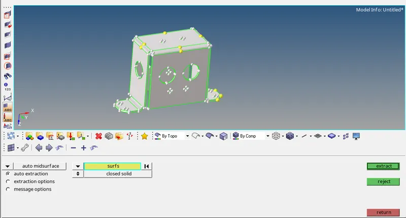
Fig.-27
3. Now, analyze the mid-surface properly, if any surface or edge is missing fix it and proceed for meshing.
4. Now go to the automesh and enter the element size as 5 and start meshing as shown in fig. 28.
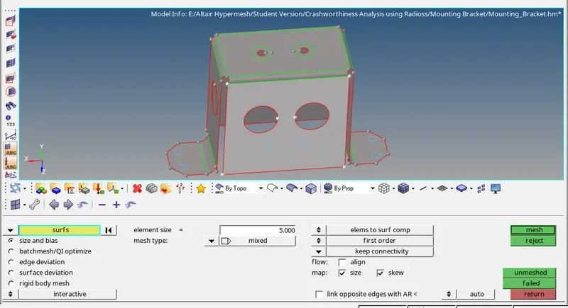
Fig.-28
5. Now, through preferences tab set the mesh criteria mentioned in the challenge as shown in fig. 29.
Fig.-29
6. Now, mesh the object. To maintain the proper mesh flow lines use the option Rebuild mesh. During meshing also pay attention towards element connectivity. If elements are connected properly using equivalence proper connectivity can be achieved. Here use the reflect option to create the mesh on other sides since the object is symmetric.
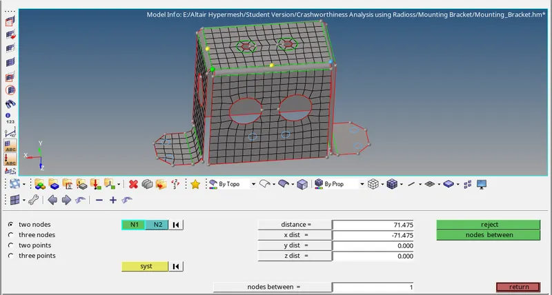
Fig.-30
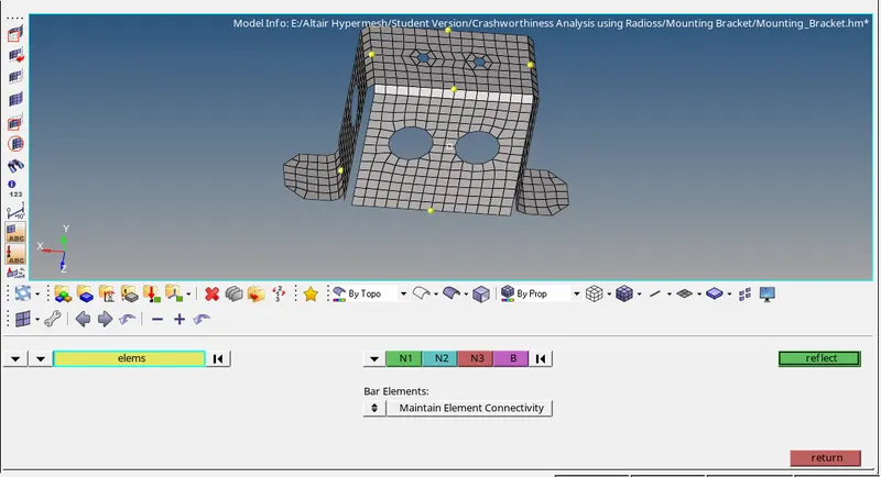
Fig.-31

Fig.-32
7. Now, assign the material to the model as shown in fig. 33.
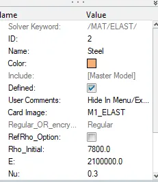
Fig.-33
8. Now create & assign the thickness as shown in fig. 34.
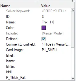
Fig.-34
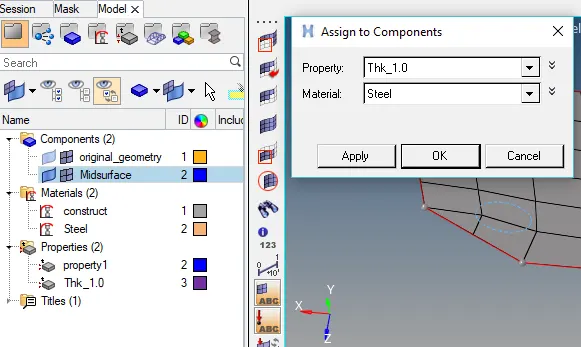
Fig.-35
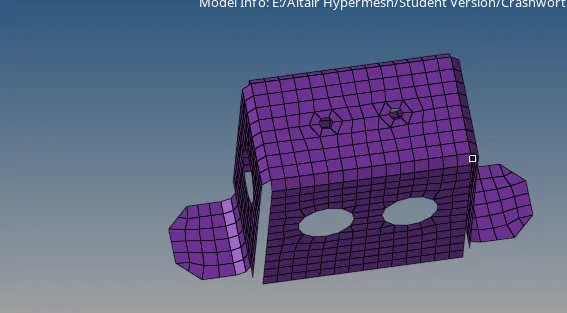
Fig.-36
Result-
As per the given criteria, given models have been meshed and achieved all quality criteria.