Assignment 1-2D Meshing Challenge
AIM:
Carry out the geometry cleanup operation on the given two models, ie, there should not be any free edges. Create 2D mesh with target length 5mm , min 3.5mm, max 7mm and assign proper thickness.
PROCEDURE:
MODEL 1
STEP 1: OPEN THE MODEL
file > Import > Model
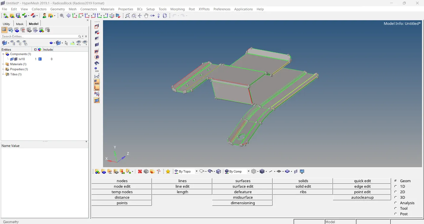
STEP 2: GEOMETRY CLEAN-UP
The model is imported the geometry is thoroughly examined and a lot of errors are examined. So using a specific set of tools as portrayed in the pictures below the geometric cleanup process is executed.
Clearing yellow lines(triple cones)
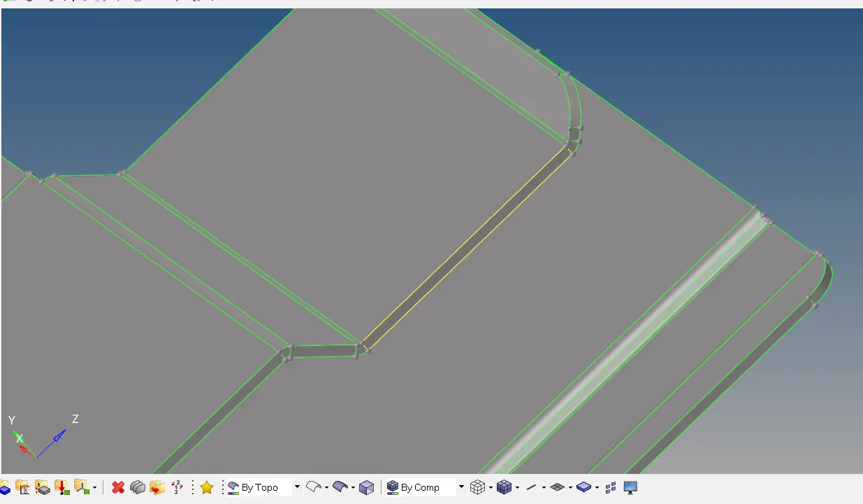
Actually the yellow lines here showing because of extra surface over there. This issue is solved by deleting the extra surface.
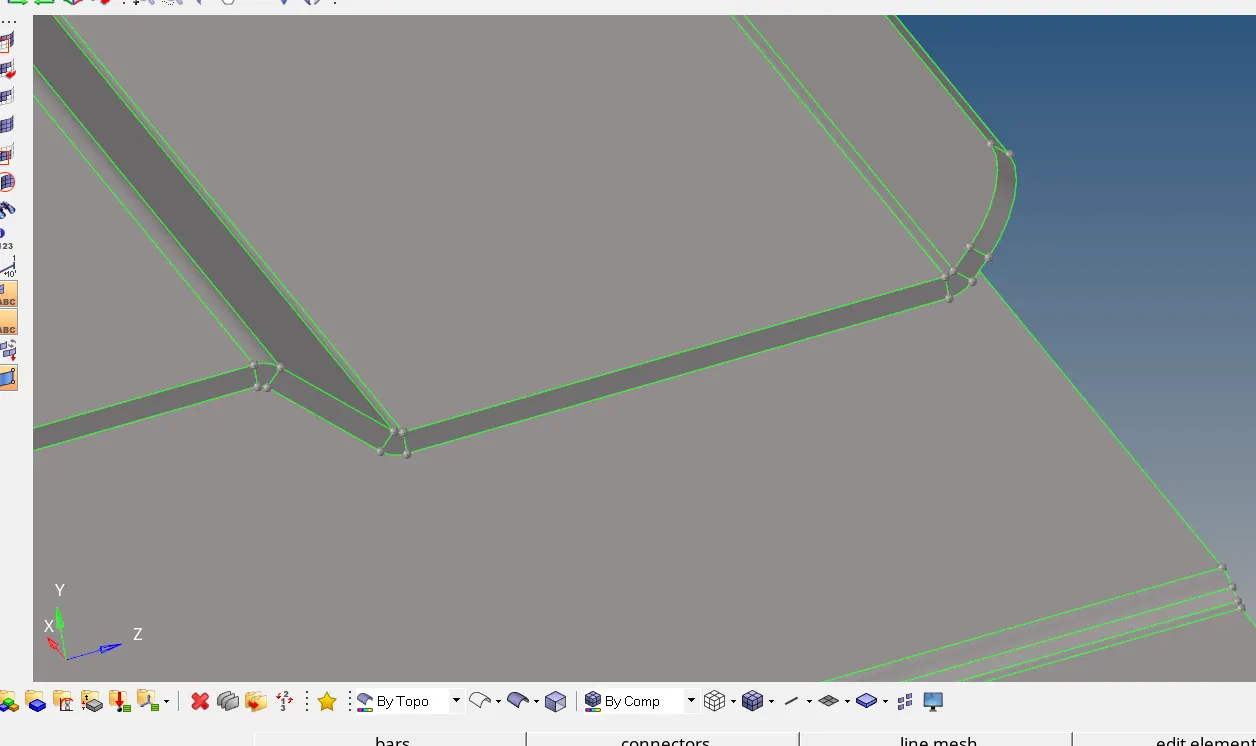
Clearing red lines( free edges)
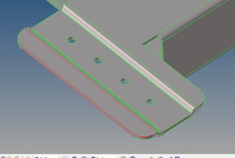
This is cleared by using TOGGLE option.
geometry > quick edit > toggle edge
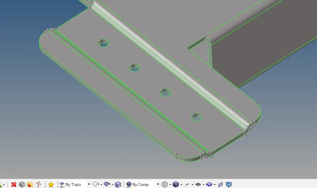
Clearing unwanted surface(extended surface)
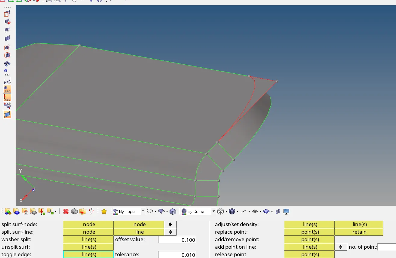
go to Geometry > Surface edit > trim with surfs/plane
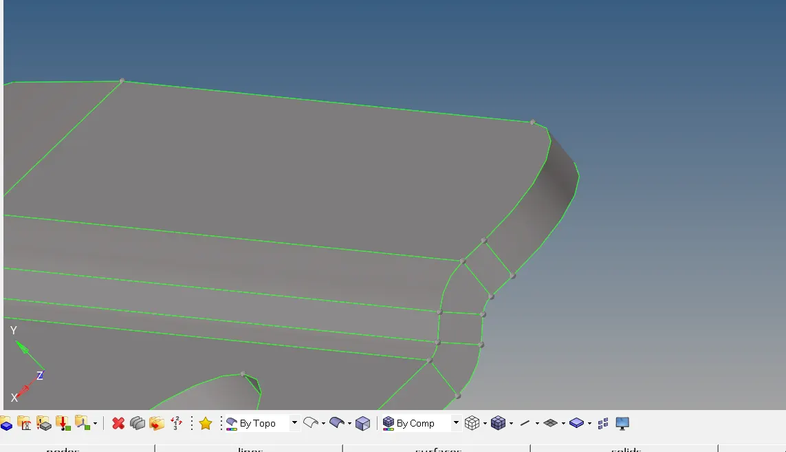
So, geometry cleanup step is completed. Here after we will not see any red or yellow line in the model by wire frame model.
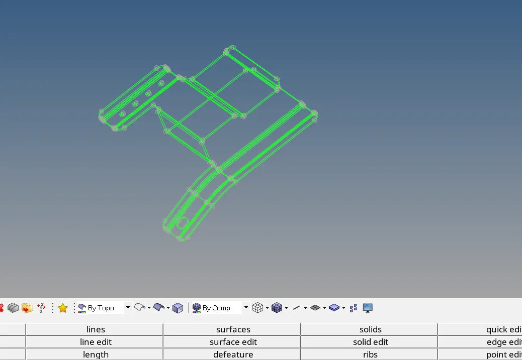
STEP 3: MID SURFACE EXTRACTION
After clearing all the geometric errors the mid surface is extracted for the component by using the auto-mid surface option. It is a sheet metal component because the thickness measured is uniform throughout.
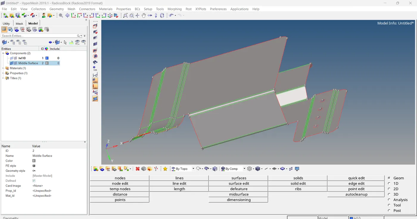
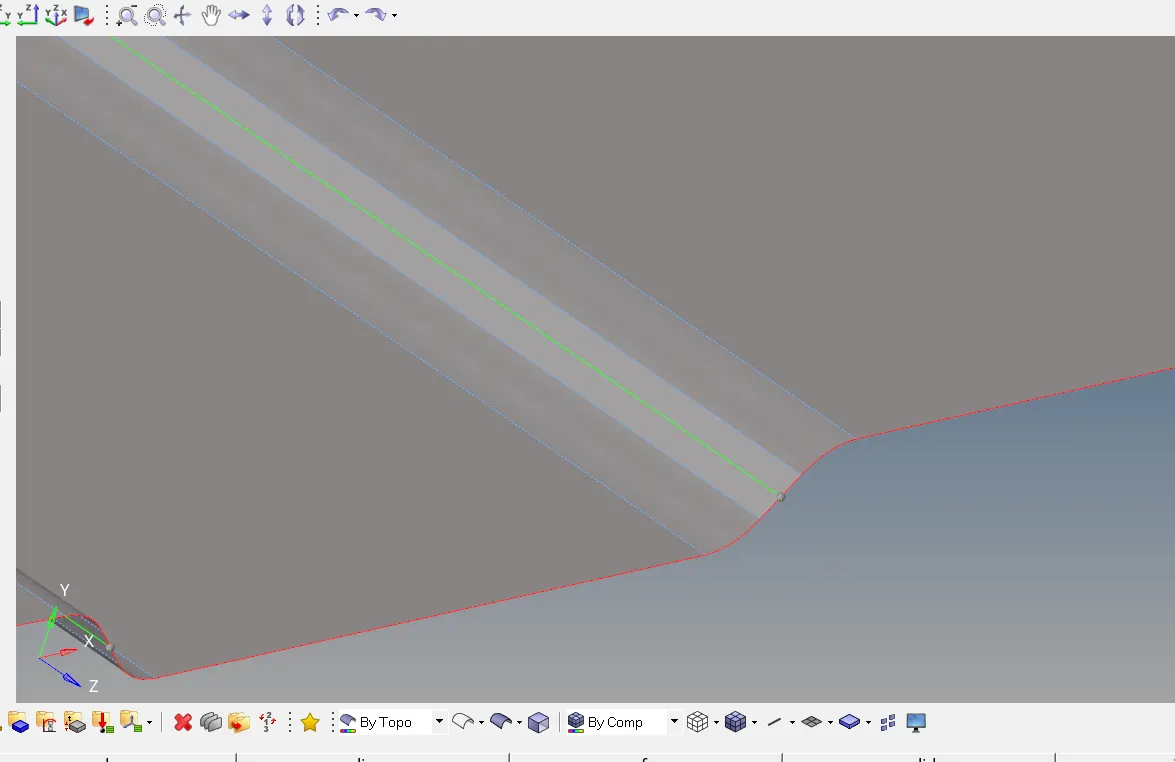
The fillets and some areas are failing for minimum element length quality criteria as per prescribed criteria setting. The unnecessary edges are defeatured and mid lines are created as displayed below.
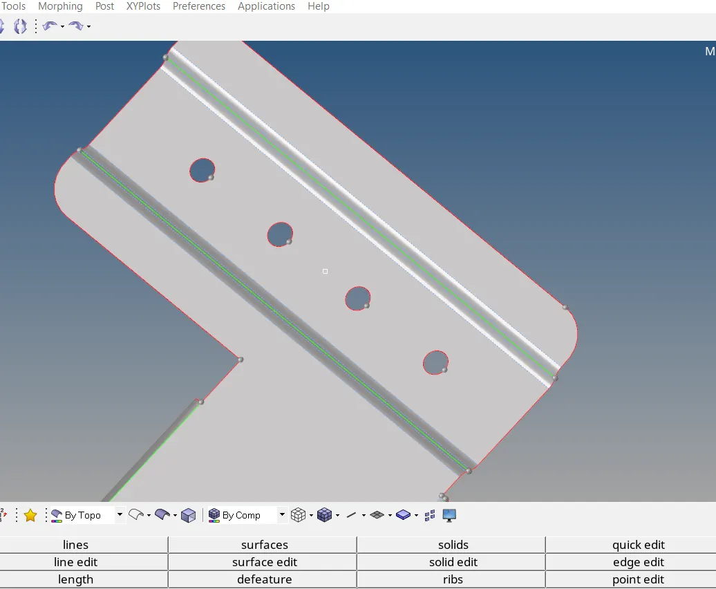
And some area has holes, these holes have diameter less than 5mm so we want to close these hole.
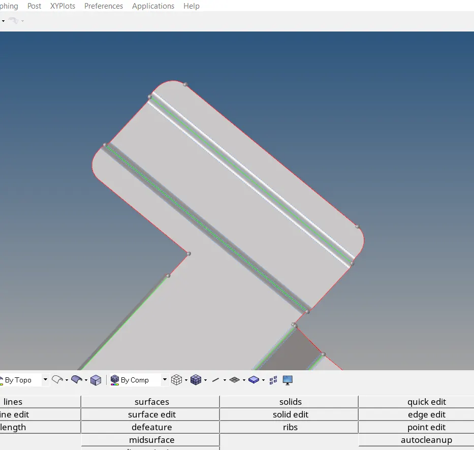
these holes closed by using geometry > quick edit > unsplit surface
STEP 4: ADDING QUALITY CRITERIA
After defeaturing the given quality criteria is inputted before meshing.
2D > element cleanup > edit criteria
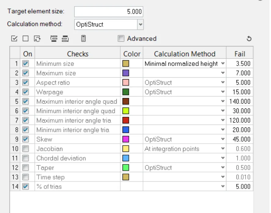
STEP 5: MESHING
Meshing is done by 2D > auto mesh
give element size as 5mm and element type as mixed.
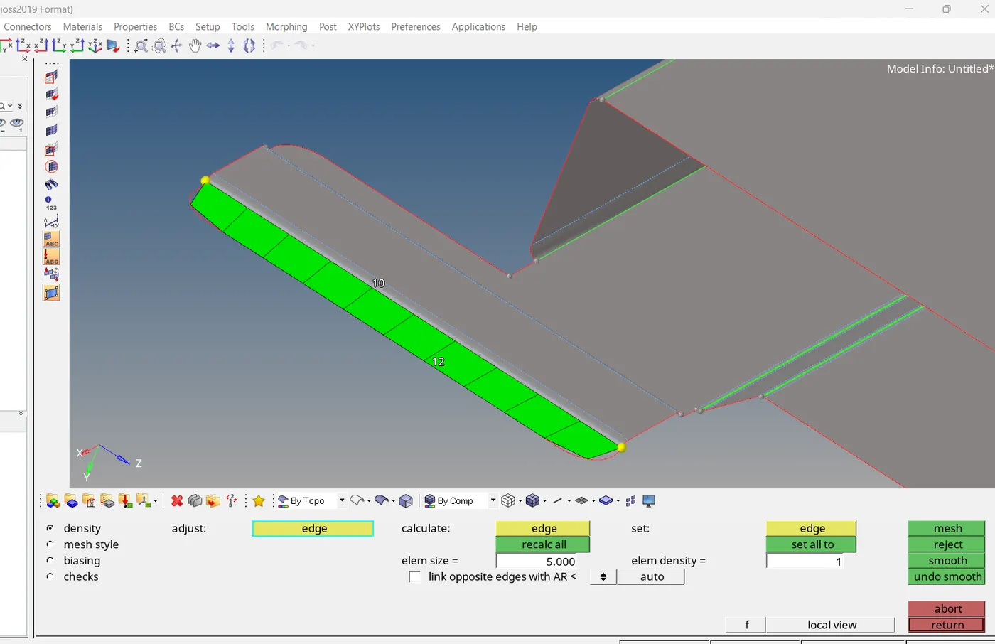
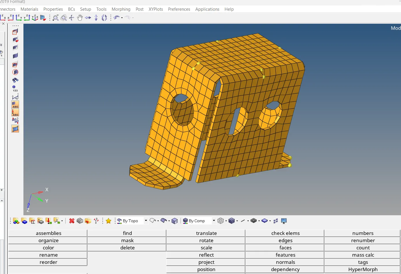
The meshing process is proceeded by using a set of tools to clear quality errors and tria on all surface of the component.
STEP 6: ASSIGNING PROPERTY
Create a property and assign the desired thickness measured from the original geometry on the mid surface.
STEP 7: ORGANISE THE MESH
After completing all the works we should add the mesh to original model.
tool > organise
Select destination component then, move.
final model
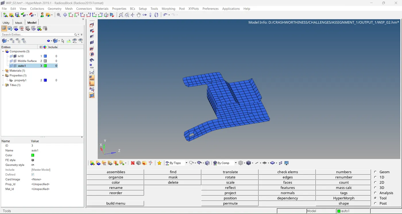
MODEL 2
STEP 1: OPEN THE MODEL
file > import > model
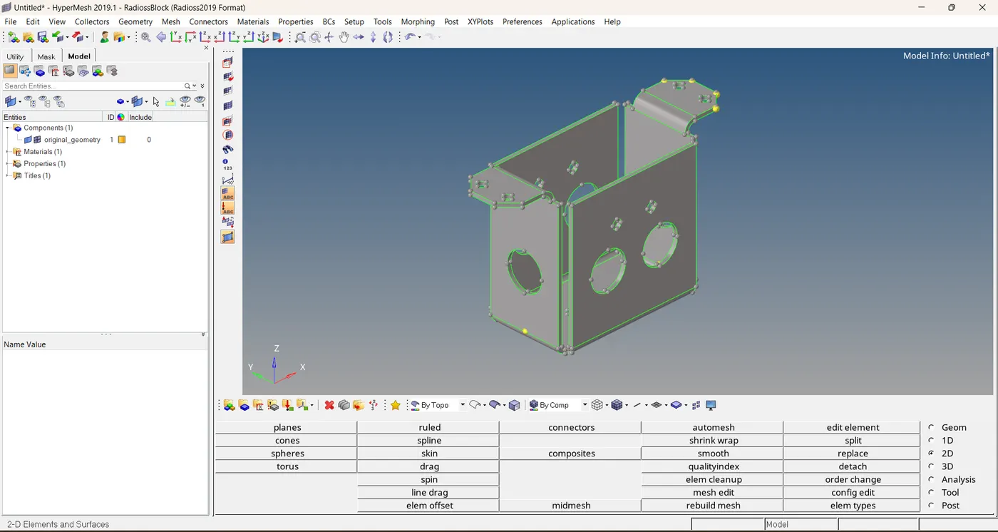
STEP 2: GEOMETRY CLEANUP
I have seen some geometric errors, Those errors solved by using replace point option.
geometry > quick edit > replace point
STEP 3: MID-SURFACE EXTRACTION
geometry > mid surface > auto mid surface
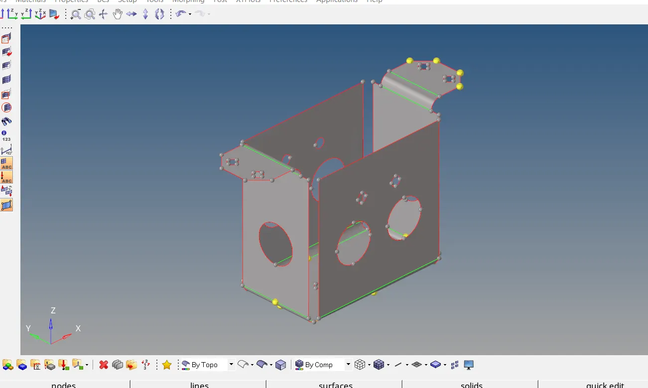
here we can fill some holes, why because those holes having diameter below 5mm.
And the washer splits are created around bigger holes.
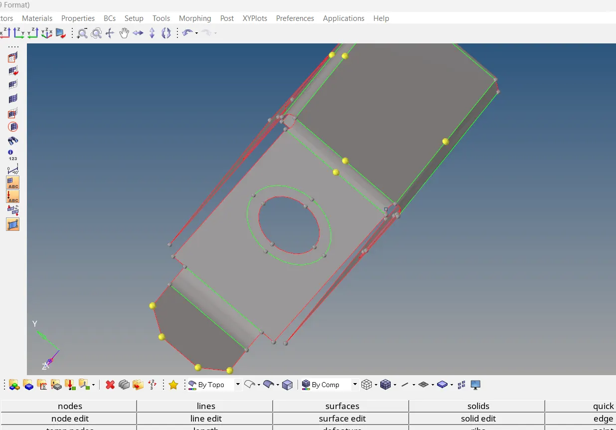
STEP 4: ADDING QUALITY CRITERIA
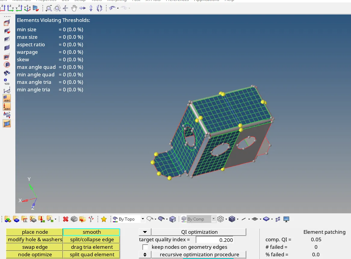
STEP 5: MESHING
Actually this model is a symmetric model, So we should mesh only on one side of the geometry and we can reflect it.
STEP 6: REFLECT
tool > reflect
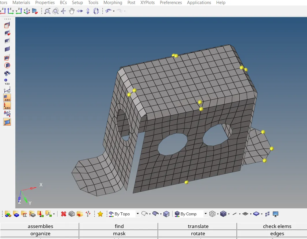
The gaps are present between the nodes of the elements which are generated using the reflect option. It is fixed by using the equivalence option using the edge tool in the panel bar.
STEP 7: ASSIGNING PROPERTY
Create a property and assign the desired thickness measured from the original geometry on the mid surface.
STEP 8: ORGANISE THE MESH
After completing all the works we should add the mesh to original model.
tool > organise
Select destination component then, move.
final model
----------------------------------Thank You--------------------------------------------