Assignment 1-2D Meshing Challenge
Crashworthiness Analysis Using Hypermesh and Radioss
#Challenge - Assignment 1 - 2D Meshing
AIM: 2D Meshing and Assigning Thickness
OBJECTIVES: Carrying out the geometry cleanup operation, Midsurface, 2D Meshing, assigning thickness by creating a generic property on the given 3 files.
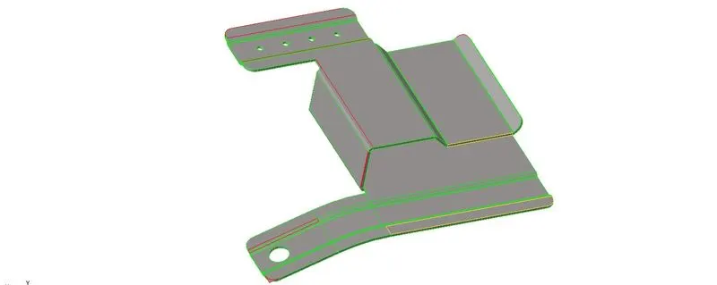
(1). Practice (Part 1)
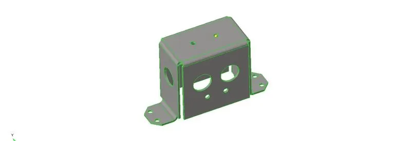
(2). Mounting Bracket (Part 2)
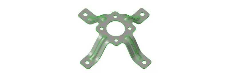
(3). Clip Repair (Part 3)
Following Criteria should be followed in all three of the models-
- Creating 2D mesh with target length 5mm, min 3.5mm max 7mm.
- Clean the geometry.
- Extracting midsurface.
- Clean mid surface geometry.
- Ignore holes less than dia 5mm.
- Assigning proper thickness, by creating a generic property.
- There should not be any free edges.
IMPORTANT PROCEDURES REQUIRED TO PERFORM IN ALL ABOVE THREE MODELS:
STEP 1: Duplicate the parent surface model to another collector to keep the parent surface safe.
STEP 2: Organise the parent surface to another component collector and duplicate the surface and move
*Tool>Organise>surface>set current component>select dest component>Duplicate>move.
STEP 3: We can see that there are many free edges,unsplit surfaces and surfaces are missing, to fix that we can go through following commands of quick edit panel
*F11>toggle edges>select lines
*F11>replace points>points>retain
*F11>surface delete
*Geom>surfaces>ruled>select line list 1>select line list 2>create
*Geom>surface edit>trim with surface>select surface 1>select surface 2>trim both
*F2>surface>select surface>delete entity
STEP 4:
- We can ignore dia less than 5mm as per given question
*F11>unsplit surface>select all holes
STEP 5: Toggle lines of geometry so that elements will not fail for minimum element length.
*F11>toggle edges>select lines
STEP 6: Measuring thickness of the component by projecting nodes on two opposite surface
*Geom>temp node>nodes>select surface>add
*Tool>project>to surface>nodes>select node>duplicate>select surface>project
*Geom>distance(F4)>two node>select nodeN1>select node N2
STEP 7: Extracting the mid surface of the component, this component is less complex and we can go through auto midsurface command.
*Geom>midsurface>auto mid surface>surface>displayed>extract
STEP 8: 2D mesh on the component
*2D>auto mesh>surface>select surface>element size(5mm)>mesh type(mixed)>mesh
STEP 9: Correcting Failed elements after setting up 2D element criteria file setting *Menu Bar>preferences>Criteria file setting
- Remesh *2D>auto mesh>elements>select elements>mesh
- Translating node *Tool>translate>nodes>select node> direction vector N1,N2>magnitude>translate + or -
- Quality index panel
- Rotating nodes *Tool>rotate>nodes>select nodes>give axis>select base node>rotate + or -
- Projecting nodes *Tool>project>to line>nodes>select nodes>select line list>project
- Checking for free edges *Shift+F3>select component>find free edges
- Connecting nodes *F3>select node of one element>select node of another element
STEP 10: Assigning thickness to elements by creating property.
-Right click on graphic area of model tree>create>properties
-Rename that particular collector with same name as mid surface and thickness
-Select component>mid surface>right click to assign>select property>apply
- Viewing Thickness of elements
*Toolbar>element colour mode (By Property)
*Toolbar>2D Detailed Element Representation
CASE SET UP AND EXECUTION
(1). Procedure for Objective 1 Practice (Part-1)
- Following Procedures from Step 1 to Step 10
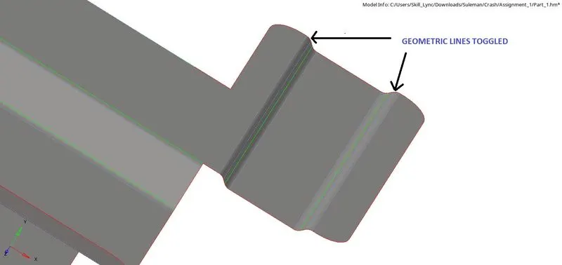
- Important command used in model is toggling geometric lines of the surfaces so that we don't face minimum element length failure.
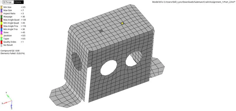
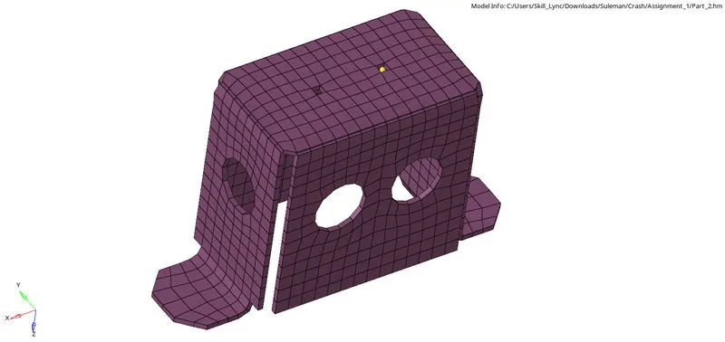
(2). Procedure for Objective 2 Mounting Bracket (Part-2)
- Following Procedures from Step 1 to Step 10
- Midsurface is extracted by taking offset surface
- Important command used in this model is ignoring a few holes in the bracket. It will again make elements nearby to fail and bad meshing in that particular area.
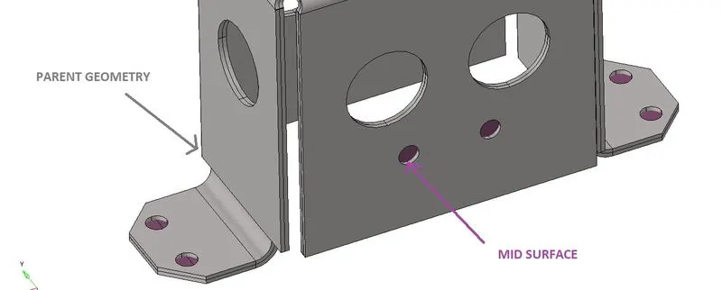
- As we can see that this bracket is symmetric so we can mesh on either side of the surface and reflect elements on the opposite side by using a reflect panel.
*Tool>reflect>elements>select elements>duplicate>current component>select axis>select base node>reflect
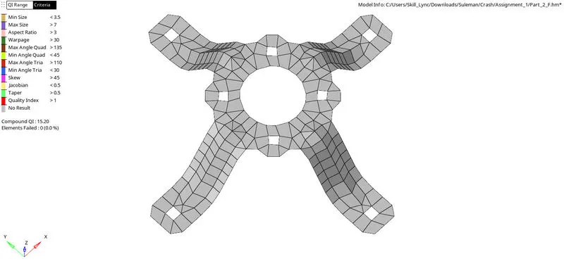
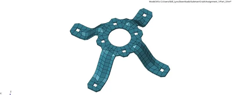
(3). Procedure for Objective 3 Mounting Clip Repair (Part-3)
- Following Procedures from Step 1 to Step 10
- Midsurface is extracted by taking offset surface
- Toggling geometric lines of the surfaces so that we don't face minimum element length failure.
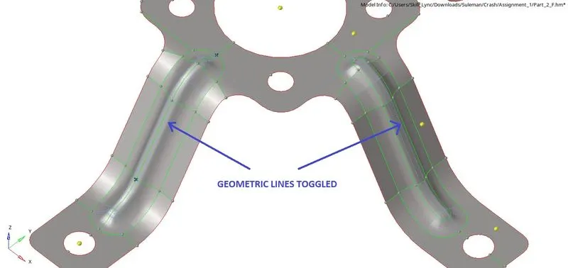
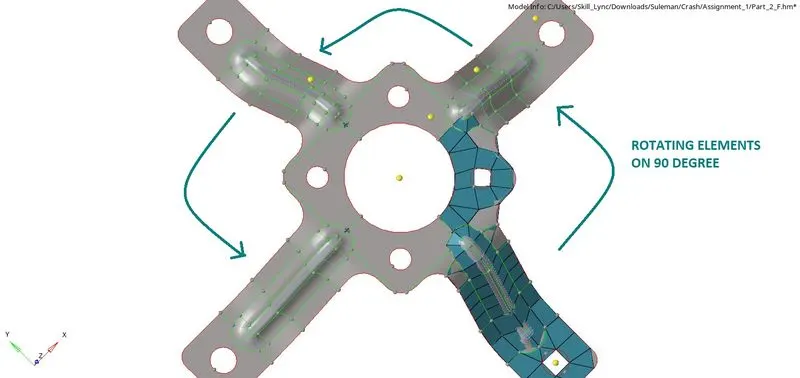
- As this is also a symmetric component and has a common axis at center hole so we can rotate the elements by 90 degree after working on one side of the component by using rotate panel. Have to rotate elements as following command three times.
*Tool>rotate>elements>select elements>duplicate>current component>select z-axis>select base node as center of component>angle 90’>rotate +
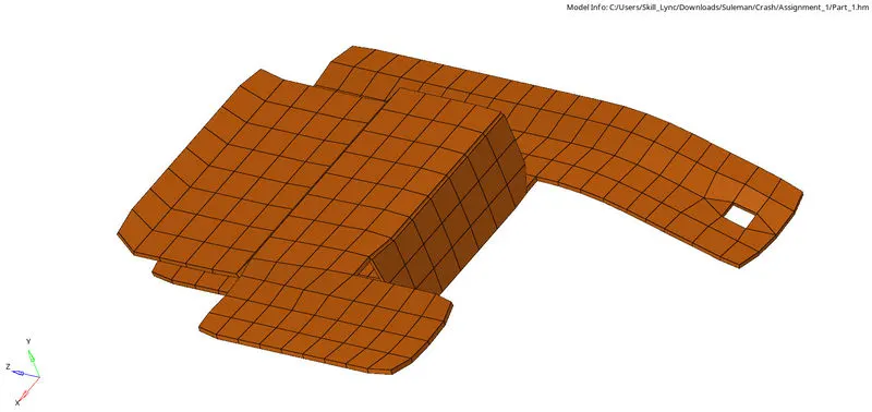
RESULTS OF OBJECTIVE 1:
- Element Quality
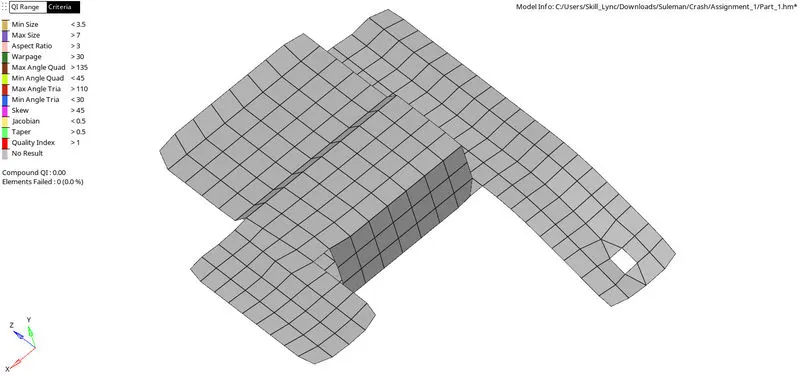
- 2D Mesh and Elements Thickness
RESULTS OF OBJECTIVE 2:
- Element Quality
- 2D Mesh and Elements Thickness
RESULTS OF OBJECTIVE 3:
- Element Quality
- 2D Mesh and Elements Thickness
LEARNINGS:
- Organising surfaces.
- Projecting nodes and lines to surface.
- Measuring thickness of surfaces.
- Extracting the mid surface manually and by auto mid surface panel.
- Geometry cleanup using a quick edit panel
- 2D Meshing
- Setting up criteria file
- Fixing failed elements using a quality index panel and remesh.
- Projecting element’s nodes to feature surfaces.
- Translating element’s node to fix failed elements.
- Finding free edges of elements and fixing it
- Assigning thickness by property.