Assignment 1-2D Meshing Challenge
Assignment 01-2D Meshing Challenge
1. Aim
- To Generate a mesh on given models after a proper geometry cleanup and mid-surface generation using Hypermesh.
- Ensure the generated mesh obeys the mentioned quality criteria and the corresponding thickness of each surface assigned to the mesh.
. Objective
- Import and perform a geometry cleanup on the given models using Hypermesh.
- Generate a Proper mid-surface with the proper technique.
- Mesh the generated mid-surface and reconstruct the mesh to satisfy the following quality criteria.
- Model Checks
Quality Criteria
| Sl No: | Quality Criteria | Value |
| 1 | Target Element Length | 5 |
| 2 | Minimum Length | 3.5 |
| 3 | Maximum Length | 7 |
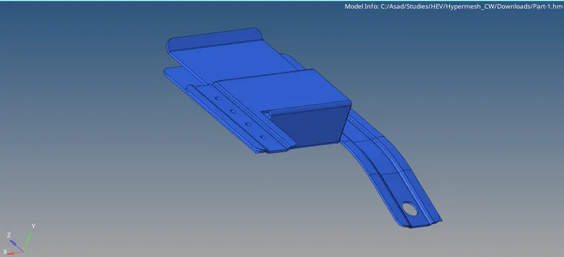
Fig 1: Isometric View Of Model 1
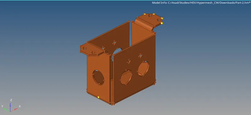
Fig 2: Isometric View Of Model 2
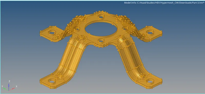
Fig 3: Isometric View Of Model 3
3. Procedure
Model 1
Step 1: Importing the File
First We have to import the file to hyper mesh. Here, the file is in .hm format.
- File >> Open >> Model >> Browse the file location >> Select The File >> Open.
Step 2: Geometry Cleanup
After loading the model, by inspecting it in topo view, we can see some errors (as red lines) are present in the geometry (missing surfaces). Using the quick edit commands 'Toggle' and 'Filler Surf' we can rectify those errors and clean the model. There is an extra surface that needs to be trimmed and deleted. Also, delete extra surfaces if there are any (Yellow Lines). there are some pin holes (<5 Units) that need to be removed to get the cleaned geometry.
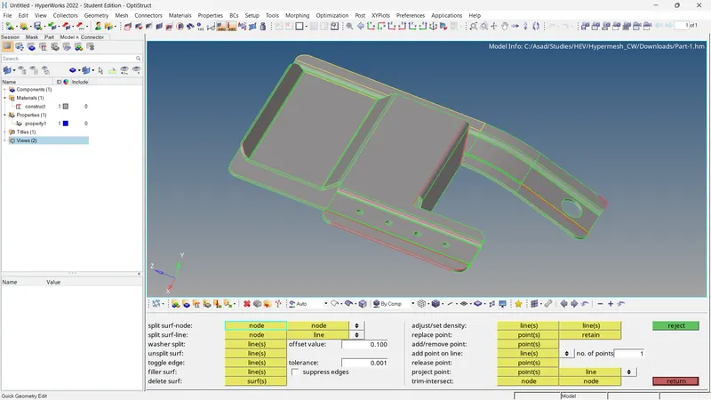
Fig 4: Before The Cleanup (Model1)
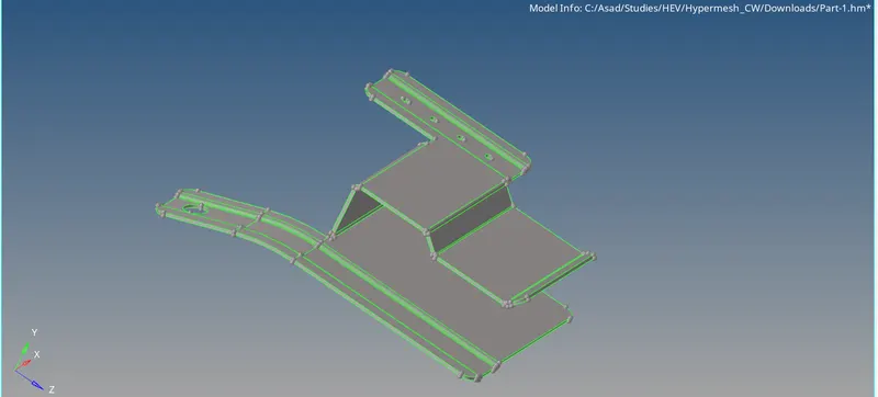
Fig 5: After The Cleanup (Model1)
The thickness of the component is measured using the 'Distance' command and it is equal to 0.91 units.
Step 2: Extracting the Midsurface And Cleaning
Then generate the mid-surface using the mid-surface option. Here we choose the extraction option as 'offset+planes+sweeps'.
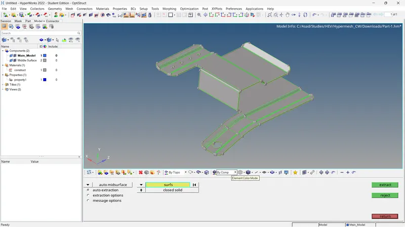
Fig 6: Mid-Surface Generation (Model_1)
After the mid-surface generation, the mid-surface needs to be cleaned. Fill the pin holes (<5mm). Toggle unwanted lines that have a chance to affect the mesh flow. Use washer splits. Remove unwanted points. If any fillet falls under the minimum radius, defeature them.
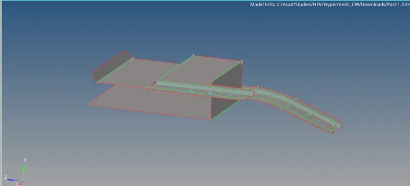
Fig 7: Mid-Surface Cleanup (Model_1)
Step 3: Property, Material, Measuring Parameters and Quality Criteria
The model has already a property and material. For property, we have to assign the Card Type = PSHELL and Thickness = 0.91 units. Also, for the material assign the Card Type = MAT1 and add to the property.
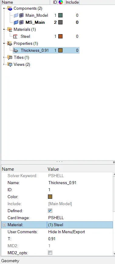
Fig 8: Property and Material (Model_1)
Add the quality criteria to the model. Besides the minimum and maximum length add other qualities like warpage, aspect ratio, minimum and maximum quad angle, minimum and maximum tria angle, jacobian, %tria and their ideal values. Save it as a file, so that we can use it for other models also. Add the measuring parameters also.
| Sl No: | Quality Criteria | Value |
| 1 | Aspect Ratio | 5 |
| 2 | Skewness | 45 |
| 3 | Warping | 15 |
| 4 | Jacobian | 0.6 |
| 5 | Min. Angle Quad | 35 |
| 6 | Max. Angle Quad | 145 |
| 7 | Min. Angle Tria | 30 |
| 8 | Max. Angle Tria | 120 |
| 9 | Tria % | 15 |
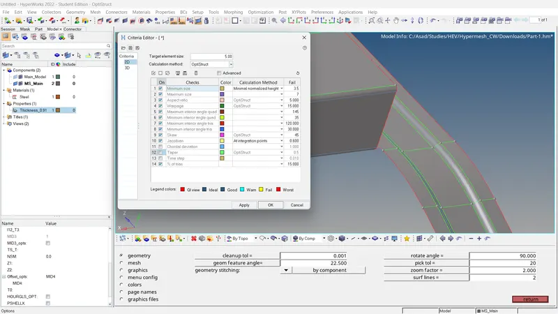
Fig 9: Quality Criteria (Model_1)
Step 4: Meshing of The Mid Surface
The meshing of the mid surface is done using auto mesh. Set the element length to 5 units. Mesh the surface and adjust the number of nodes until the mesh flow becomes better.
- 2D >> Automesh >> Select Surface >> Ok.
The mesh flow should be improved especially in feature areas. For that, there are plenty of tools in the hyper mesh that can be used for the correction of mesh flow. In this case following options are used,
- 2D >> edit element >> Create/Combine/Split
- 2D >> rebuilt >> Select the mesh elements to be reconstructed.
Also using the rotate option, we can rotate the nodes of holes to 90 degrees, so that the mesh flow becomes much better.
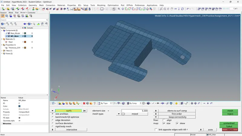
Fig 10: Generated Mesh (Model_1)
After correcting the mesh flow, the element quality should be checked.
- 2D >> Quality Index >> Cleanup Tools >> Place nodes/Smooth/Modify holes and washers/Split and Collapse Edge/Swap edge/Drag tria element/node optimise/element optimise/split quad element/combine tria element.
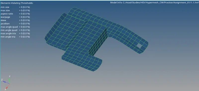
Fig 11: Quality Index (Model_1)
Step 5: Model Checks
Check For Free Edges And Equivalence
- Tools >> Edges >> Select Elements >> Adjust The Tolerance Value (~0.5) >> Find edges.
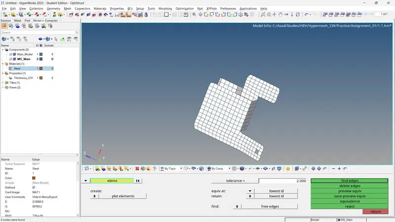
Fig 12: Check For Free Edges and Equivalence (Model_1)
Check For Normals
- Tools >> Normal >> Elements >> Color Display >> Vector Display >> Size= 10 >> Display.
If any of the vectors have opposite directions, it can be corrected by Using the 'Adjust' option.
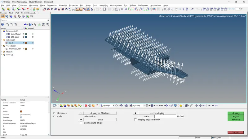
Fig 13: Check For Normals (Model_1)
Check For Connectivity and Duplicates
Checking connectivity between elements and the presence of duplicate elements,
For Connectivity
- Tools >> Check Elements >> 2D >> Connectivity
To find duplicates,
- Tools >> Check Elements >> 2D >> Duplicates
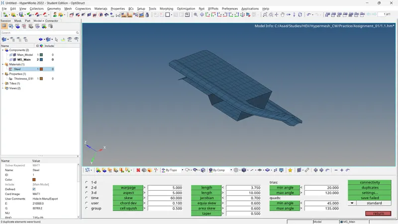
Fig 14: Check For Connectivity and Duplicates. (Model_1)
Check For Penetration and Dependency
For penetration/intersections checks,
- Tools >> Penetration >> Select Elements >> Check
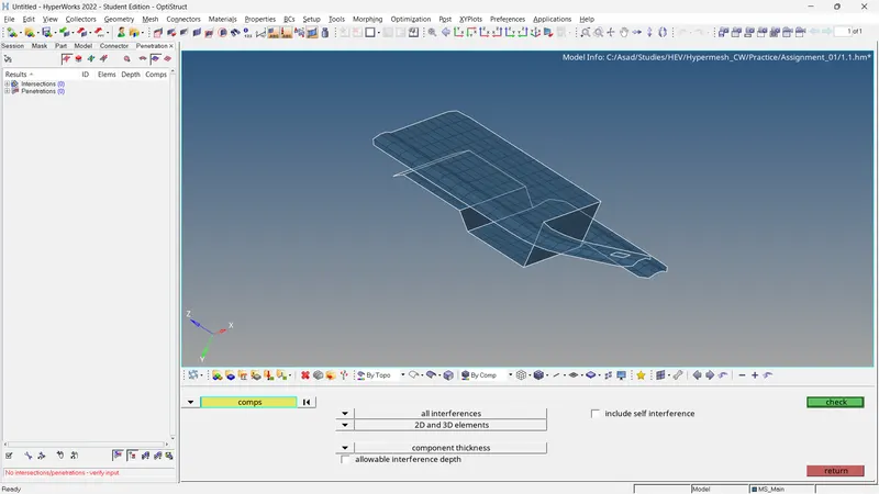
Fig 15: Check For Penetration/Intersections (Model_1)
For dependency checking,
- Tools >> Dependency >> Select Elements >> Dependency
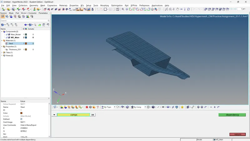
Fig 16: Check For Dependency (Model_1)
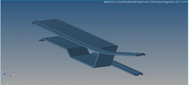
Fig 17: Final Result (Model_1)
Model 2
Step 1: Extracting the Midsurface And Cleaning
By inspecting the model, we can see that there are no errors in the geometry. Only some nodes are replaced and lines are toggled. After that, we can directly go for the mid-surface generation. Before that, we can measure the thickness and it is equal to 2 units. Here we choose the extraction option as 'offset+planes'.
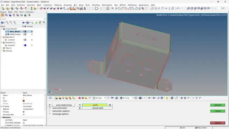
Fig 18: Mid-Surface Generation (Model_2)
After the mid-surface generation, the Same as previous, the mid-surface needs to be cleaned. Fill the pin holes (<5mm). Toggle unwanted lines that have a chance to affect the mesh flow. Use washer splits. Remove unwanted points. Add points to the edges of lines.
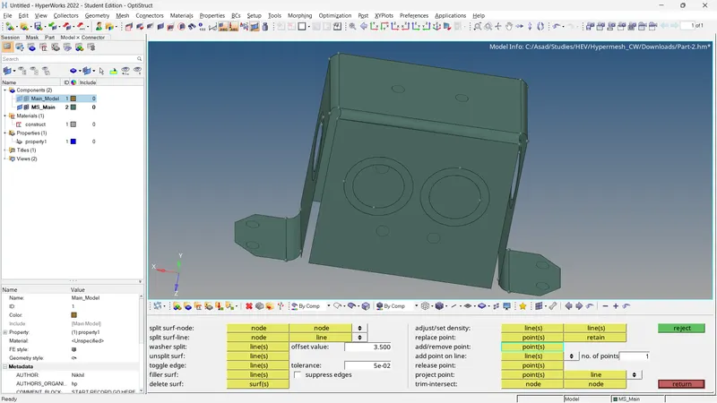
Fig 19: Mid-Surface Cleanup (Model_2)
Step 2: Property, Material, Measuring Parameters and Quality Criteria
Also, this model has a property and material. For property, we have to assign the Card Type = PSHELL and Thickness = 2.0 units. Also, for the material assign the Card Type = MAT1 and add to the property.
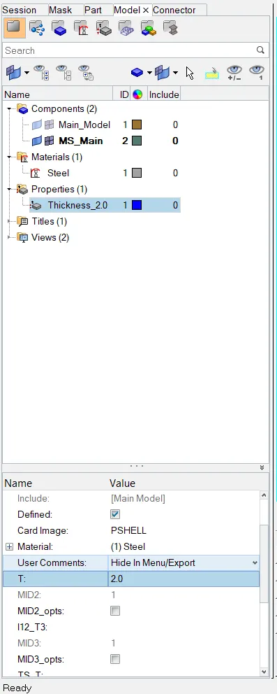
Fig 20: Property and Material (Model_2)
For quality criteria, we can open and load the quality criteria for Model_1.
Step 3: Meshing of The Mid Surface
The meshing of the mid surface is done using auto mesh. Set the element length to 5 units. Mesh the surface and adjust the number of nodes until the mesh flow becomes better.
- 2D >> Automesh >> Select Surface >> Ok.
Here we can use the translate option to copy duplicated elements and move to the other side where have the same shapes. Then try to equivalence the nodes. On one side, we need to use both translate and then rotate those elements 180 degrees in the z-axis.
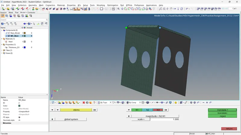
Fig 20: Using Translate Option (Model_2)
The mesh flow should be improved especially in feature areas. For that, there are plenty of tools in the hyper mesh that can be used for the correction of mesh flow. In this case following options are used,
- 2D >> edit element >> Create/Combine/Split
- 2D >> rebuilt >> Select the mesh elements to be reconstructed.
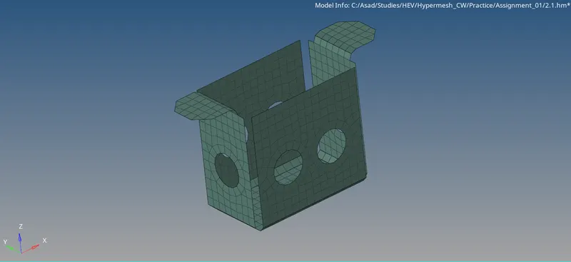
Fig 21: Generated Mesh (Model_2)
After correcting the mesh flow, the element quality should be checked.
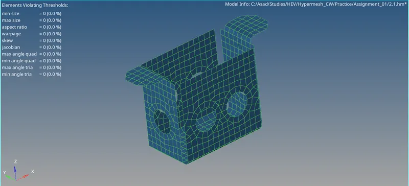
Fig 22: Quality Index (Model_2)
Step 4: Model Checks
Check For Free Edges And Equivalence
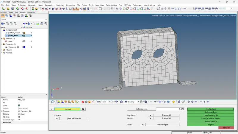
Fig 23: Check For Free Edges and Equivalence (Model_2)
Check For Normals
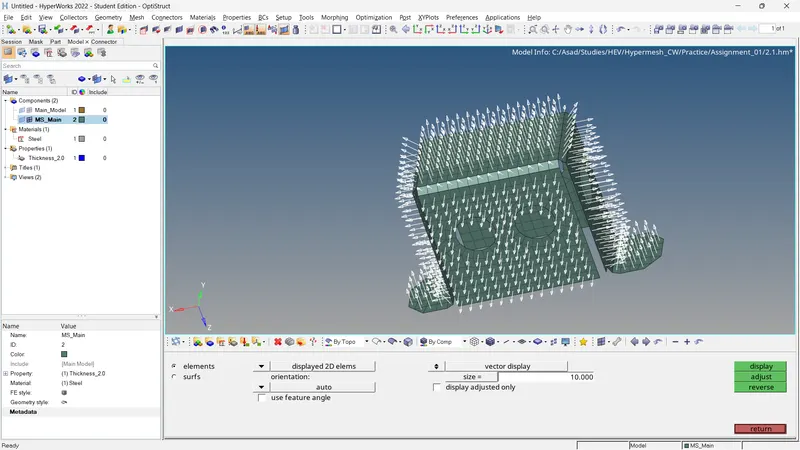
Fig 24: Check For Normals (Model_2)
Check For Connectivity and Duplicates
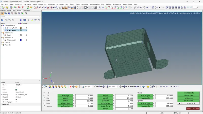
Fig 25: Check For Connectivity and Duplicates. (Model_2)
Check For Penetration and Dependency
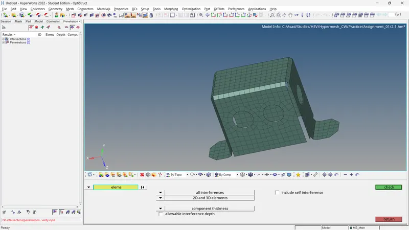
Fig 26: Check For Penetration/Intersections (Model_2)
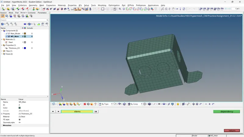
Fig 27: Check For Dependency (Model_2)
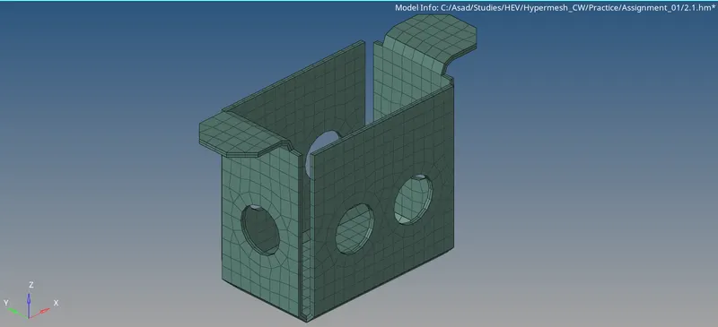
Fig 28: Final Result (Model_2)
Model 3
Step 1: Extracting the Midsurface And Cleaning
By inspecting the model, we can see that there are no errors in the geometry. Only some nodes are replaced and lines are toggled. After that, we can directly go for the mid-surface generation. Before that, we can measure the thickness and it is equal to 1.8 units. Here we choose the extraction option as 'offset+planes'.
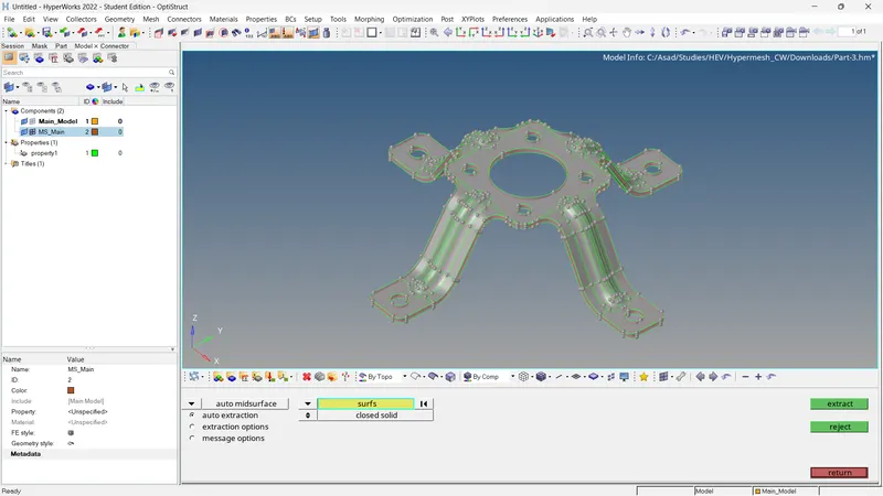
Fig 29: Mid-Surface Generation (Model_3)
The mid-surface is symmetrical. So we can divide it into 4 parts, mesh one of the parts and reflect it using the rotate option. So using the trim option we can divide with the help of nodes. Toggle unwanted lines and fill the pin holes having a radius of <5 units.
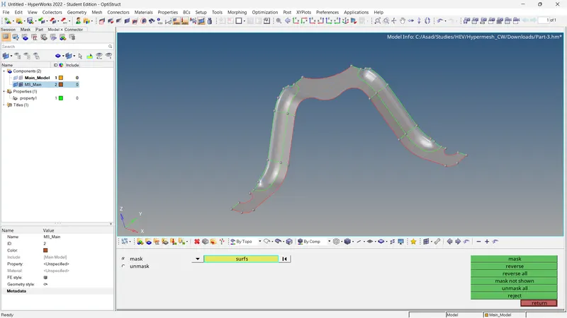
Fig 30: Mid Surface Division (Model_3)
Step 2: Property, Material, Measuring Parameters and Quality Criteria
Also, this model has a property. For property, we have to assign the Card Type = PSHELL and Thickness = 1.8 units. Create material and assign it to the property. Browse and load the quality criteria for the mesh.
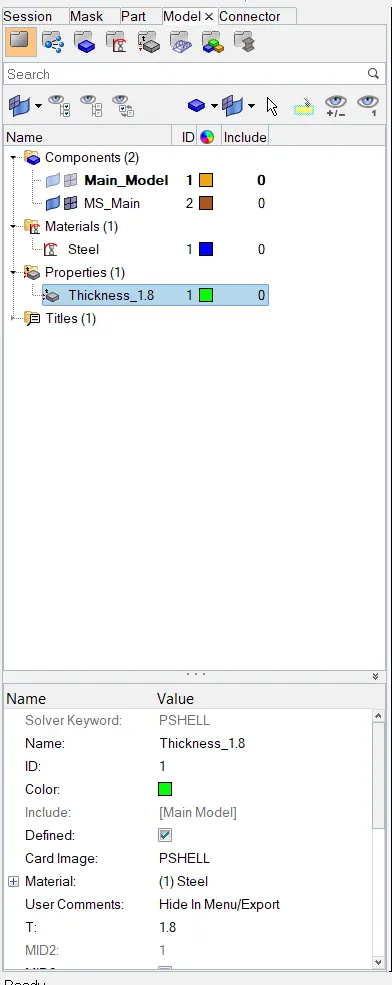
Fig 31: Property and Material (Model_3)
Step 3: Meshing of The Mid Surface
The meshing of the one-fourth of mid surface is done using auto mesh. Set the element length to 5 units. Mesh the surface and adjust the number of nodes until the mesh flow becomes better.
Then using the rotate option, we can duplicate and rotate the elements in 90 degrees in the z-axis. Then perform equivalence. After that, select all elements and duplicate and rotate the elements 180 degrees on the z-axis and perform equivalence.
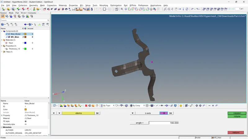
Fig 32: Using Rotate Option (Model_3)
The mesh flow should be improved especially in feature areas. For that, there are plenty of tools in the hyper mesh that can be used for the correction of mesh flow.
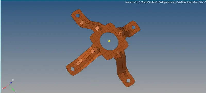
Fig 33: Generated Mesh (Model_3)
After correcting the mesh flow, the element quality should be checked.
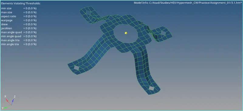
Fig 34: Quality Index (Model_3)
Step 4: Model Checks
Check For Free Edges And Equivalence
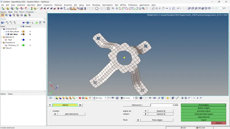
Fig 35: Check For Free Edges and Equivalence (Model_3)
Check For Normals
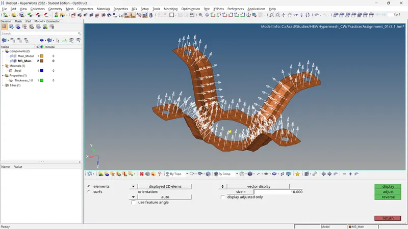
Fig 36: Check For Normals (Model_3)
Check For Connectivity and Duplicates
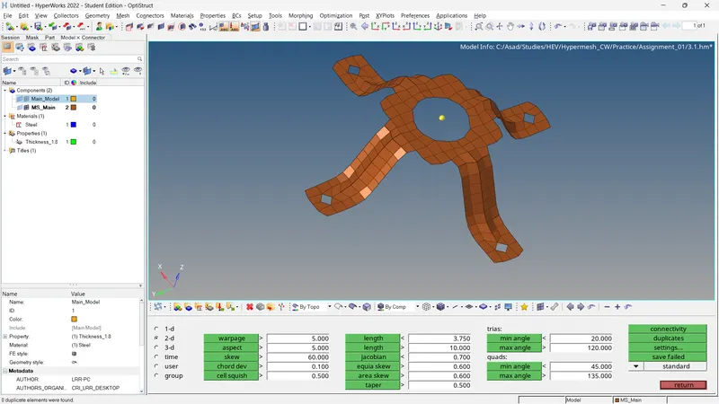
Fig 37: Check For Connectivity and Duplicates. (Model_3)
Check For Penetration and Dependency
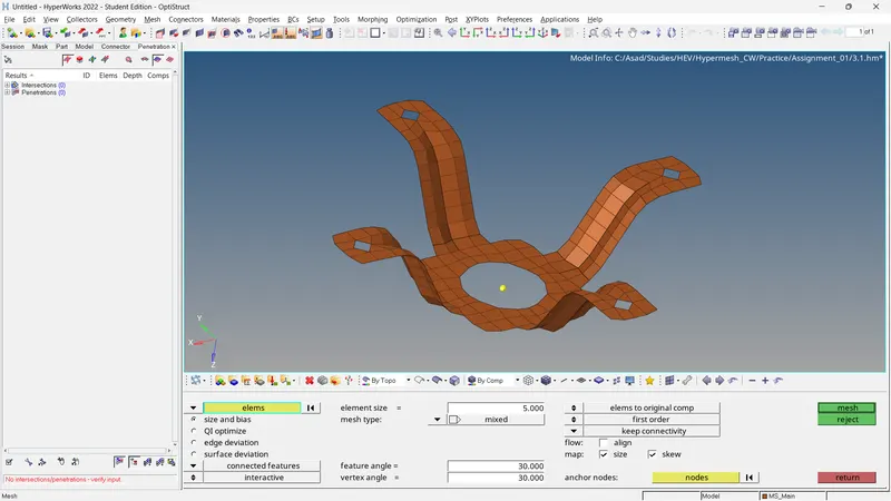
Fig 38: Check For Penetration/Intersections (Model_3)
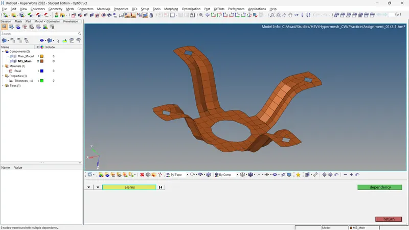
Fig 39: Check For Dependency (Model_3)
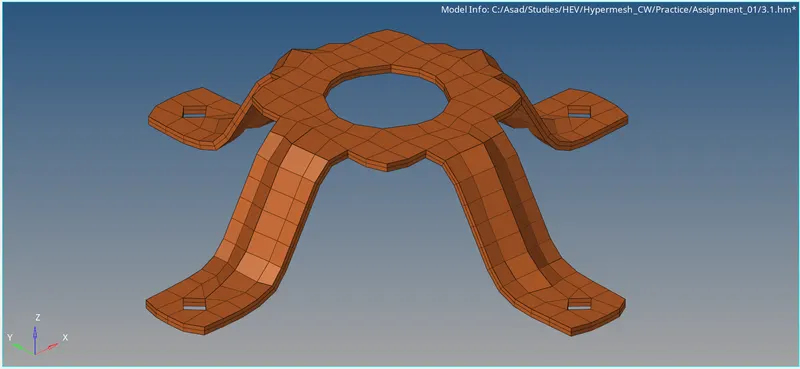
Fig 40: Final Result (Model_3)
4. Conclusion
- The mid surface of the given model is generated, assigned properties, and materials and adds quality criteria and target element lengths for every one of the models.
- The meshing and reconstruction of a generated mesh of each model are completed.
- Model checking is finished.
5. Results
- For the given models, the mid-surface is extracted and mesh generated. The generated mesh satisfies the following quality criteria and the model checks are completed.