Assignment 1-2D Meshing Challenge
Geometry Cleanup & 2D Meshing Report
Aim:
To clean the geometry errors present in the given model making the model without any free edges on the surfaces and thereby meshing and finally assigning thickness for each of the given models.
Part-1 Procedure:
Geometry Cleanup:
For geometry clean-up, first, the given model was imported into Hypermesh software using the IMPORT MODEL option under the IMPORT tab.
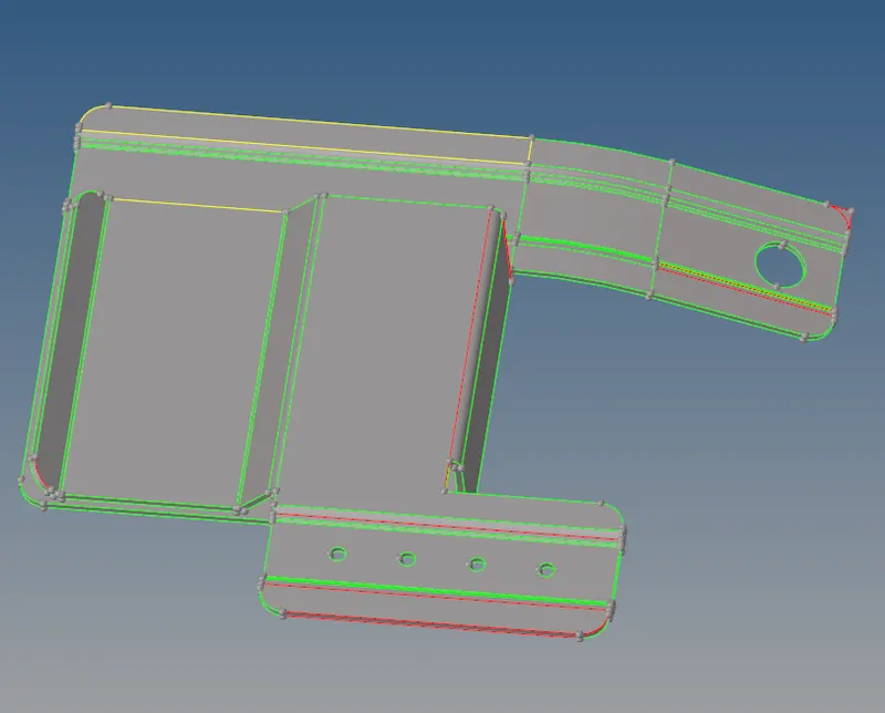
Fig.1 Part-1 Model.
After importing the model, it was found that the given model had missing surfaces, surface irregularities, and free edges. There are two ways to clean the geometrical errors. One is using the Autoclean option and the other is Manual clean-up.
Mid Surface Extraction:
For the mid surface to be extracted using auto mid, then the model should be a closed volume. But the figure shows there were open surfaces which means the model is not a closed one. Thereafter the geometry cleanup was carried out to ensure that there are no topological errors and open volumes. So, in this model Manual Clean up was performed and geometrical errors were cleared. After all the errors were removed and making the model a closed volume, the auto mid option can be used to extract the mid surfaces. So using the MIDSURFACE-AUTOMIDSURFACE option from the GEOMETRY menu tool was used. Figure 3 shows the mid surfaces extracted using the auto mid option. Holes with a diameter of less than 5mm were closed as specified.
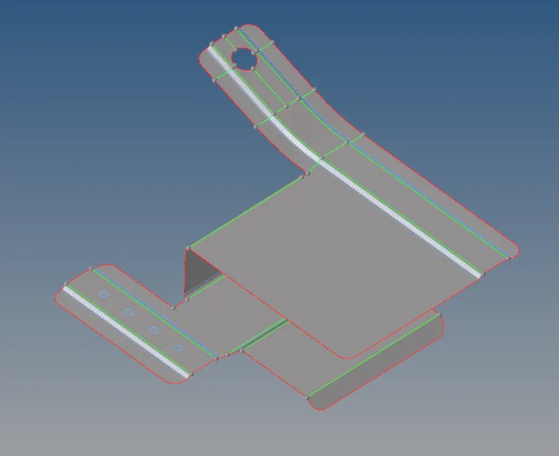
Fig. 2 After clean-up.
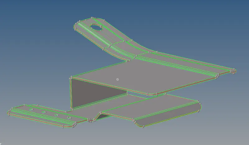
Fig.3 Mid Surface Extracted.
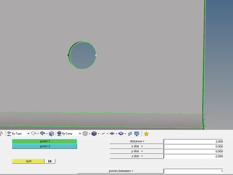
Fig.4 Holes of 5mm diameter
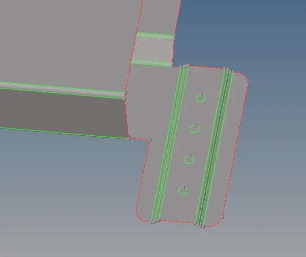
Fig.5 Holes Closed.
Some fillets were defeatured since the fillet radius was smaller than the minimum element length, while some others were suppressed due to minimum element length.
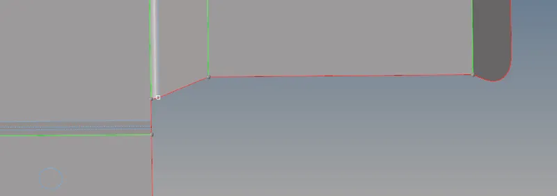
Fig.6 Fillets defeatured and suppressed.
Meshing:
After Mid Surface Extraction and auto clean-up, meshing has been carried out on the mid-surface with the following mesh parameters shown in figure 7.

Fig.7 Mesh Parameters.
The mesh was carried out using the AUTOMESH option from the 2D menu bar. Figure 8 shows the mesh created on the mid-surface extracted.
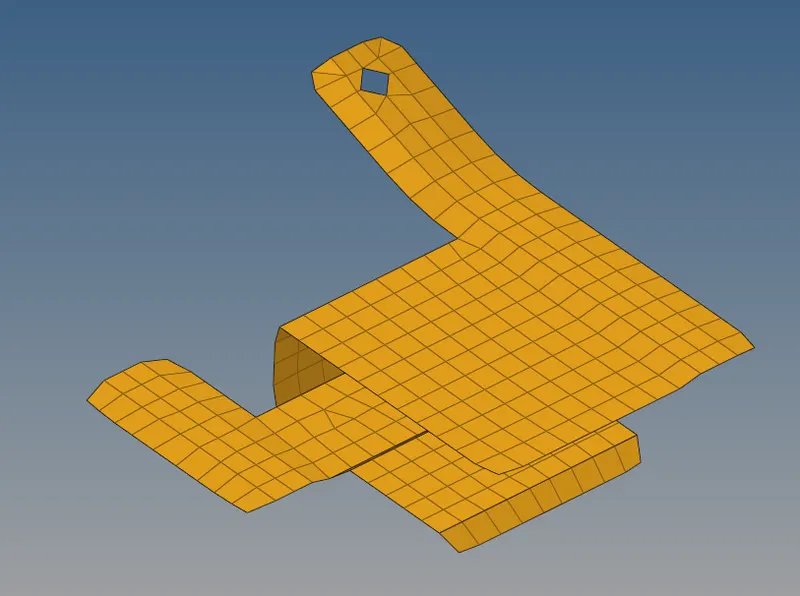
Fig.8 Mid Surface Meshed.
Quality Checks:
After mid-surface meshed, quality checks have to be performed and the mesh should be free from quality errors. Figure 9 shows the Quality Criteria set for the given model.

Fig.9 Quality Criteria Check.
The quality check was performed and quality errors were cleared. The mesh model free from quality error is shown the figure 11.
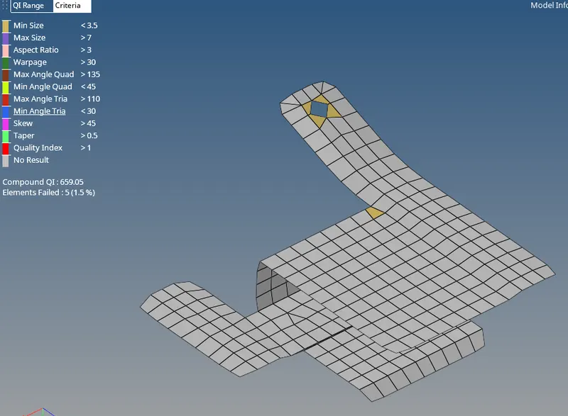
Fig.10 Quality Checks performed on the mesh.
After clearing all the quality issues, elements normals were checked using the NORMAL option from the TOOL menu.
Assigning Thickness: The model has been provided with respective properties namely Thickness, Material, Name, and Ids. Finally, the elements were drawn as solids. The mesh elements of the entire model are drawn as 2D DETAILED ELEMENT REPRESENTATION to reflect the actual CAD geometry. Figure 12 shows the final model along with CAD Geometry.
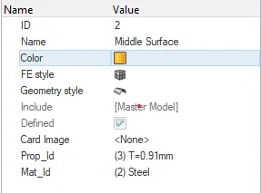
Fig.11 Thickness Property assigned.
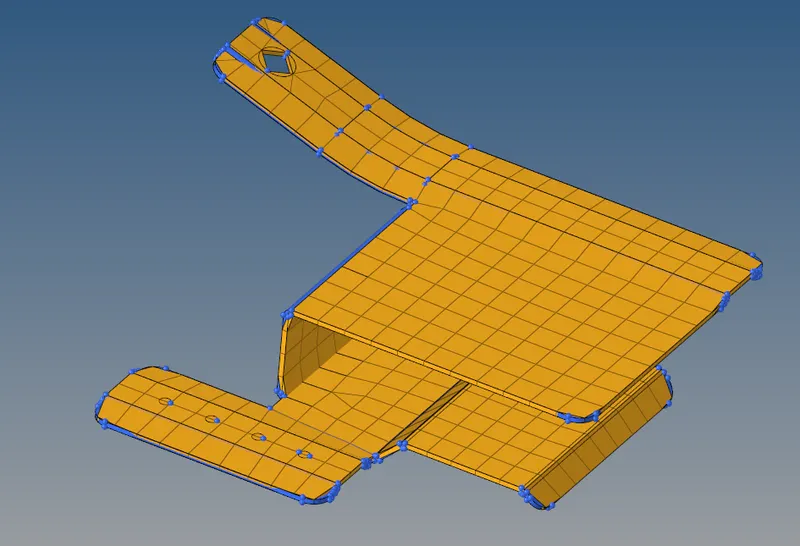
Fig.12 Final Part-1 Model.
Part-2 Procedure:
Geometry Cleanup:
For geometry clean-up, first, the given model was imported into Hypermesh software using the IMPORT MODEL option under the IMPORT tab.
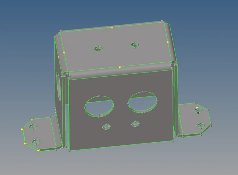
Fig.13 Part-2 Model.
Mid Surface Extraction:
For the mid surface to be extracted using auto mid, then the model should be a closed volume. After making the model a closed volume, the auto mid option can be used to extract the mid surfaces. So using the MIDSURFACE-AUTOMIDSURFACE option from the GEOMETRY menu tool was used. Figure 14 shows the mid surfaces extracted using the auto mid option. Holes with a diameter of less than 5mm were closed as specified.
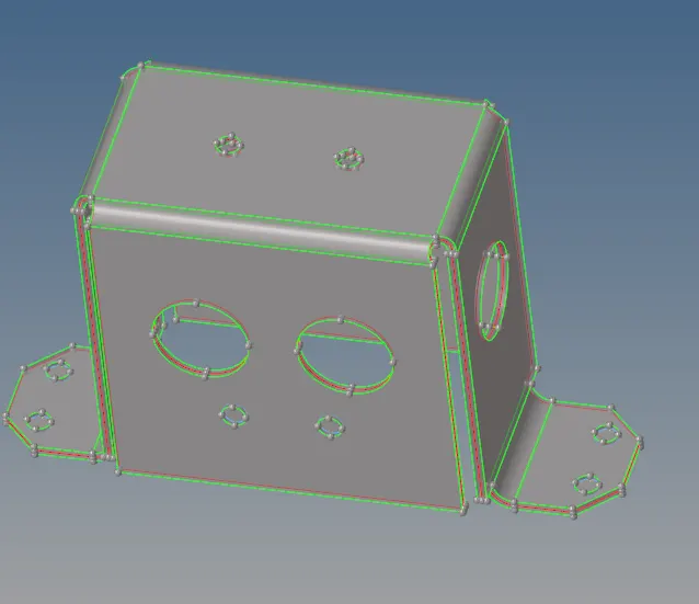
Fig.14 Mid Surface Extracted.
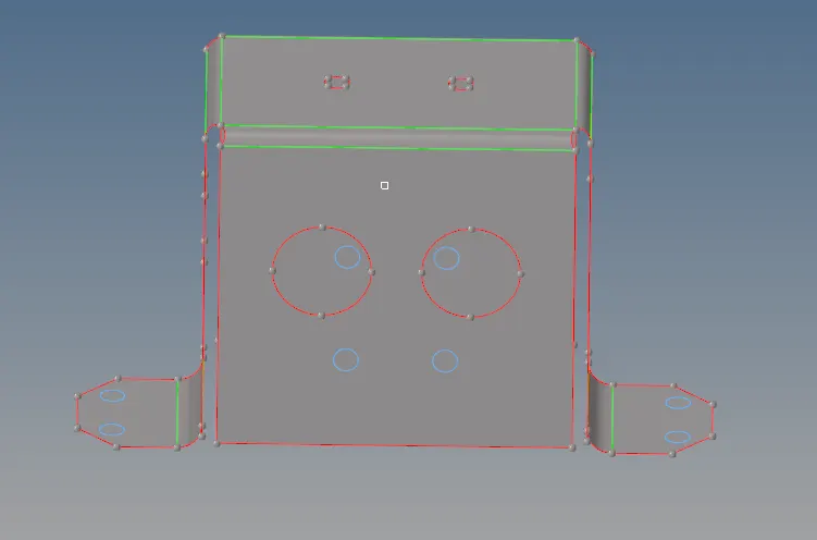
Fig.15 Holes Closed.
Meshing:
After Mid Surface Extraction and auto clean-up, meshing has been carried out on the mid-surface with the following mesh parameters shown in figure 16.
Fig.16 Mesh Parameters.
The mesh was carried out using the AUTOMESH option from the 2D menu bar. Figure 17 shows the mesh created on the mid-surface extracted.
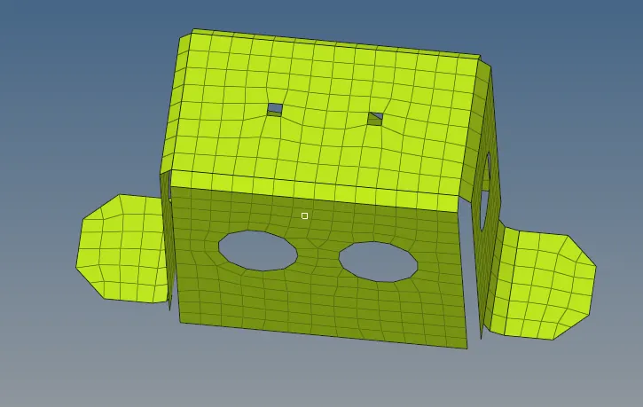
Fig.17 Mid Surface Meshed.
Since the Part-2 Model looks Symmetrical, the mesh is copied and reflected on the other side using the TOOLS – REFLECT option.

Fig. 18 Reflect Option.
Quality Checks:
After mid-surface meshed, quality checks have to be performed and the mesh should be free from quality errors. Figure 19 shows the Quality Criteria set for the given model.
Fig.19 Quality Criteria Check.
The quality check was performed and quality errors were cleared. The mesh model free from quality error is shown the figure 20.
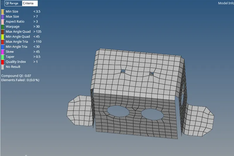
Fig.20 Quality Checks performed on the mesh.
After clearing all the quality issues, elements normals were checked using the NORMAL option from the TOOL menu.
Assigning Thickness: The model has been provided with respective properties namely Thickness, Material, Name, and Ids. Finally, the elements were drawn as solids. The mesh elements of the entire model are drawn as 2D DETAILED ELEMENT REPRESENTATION to reflect the actual CAD geometry. Figure 22 shows the final model along with CAD Geometry.
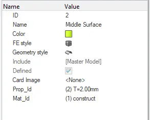
Fig.21 Thickness Property assigned.
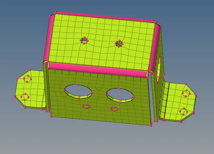
Fig.22 Final Part-2 Model.
Part-3 Procedure:
Geometry Cleanup:
For geometry clean-up, first, the given model was imported into Hypermesh software using the IMPORT MODEL option under the IMPORT tab.
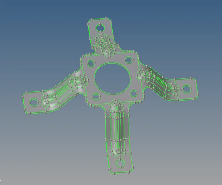
Fig.23 Part-3 Model.
Mid Surface Extraction:
For the mid surface to be extracted using auto mid, then the model should be a closed volume. After making the model a closed volume, the auto mid option can be used to extract the mid surfaces. So using the MIDSURFACE-AUTOMIDSURFACE option from the GEOMETRY menu tool was used. Figure 24 shows the mid surfaces extracted using the auto mid option. Holes with a diameter of less than 5mm were closed as specified. Later Geometry cleaning was performed.
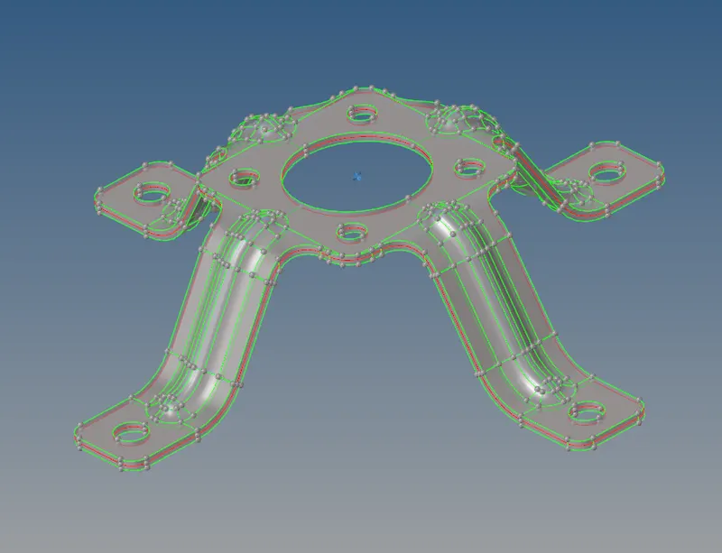
Fig.24 Mid Surface Extracted.
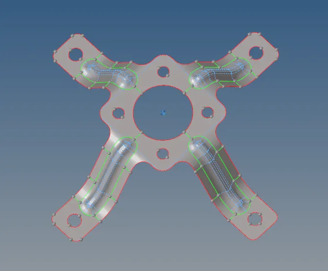
Fig.25 Clean-up performed.
Meshing:
After Mid Surface Extraction and auto clean-up, meshing has been carried out on the mid-surface with the following mesh parameters shown in figure 26.
Fig.26 Mesh Parameters.
The mesh was carried out using the AUTOMESH option from the 2D menu bar. Figure 27 shows the mesh created on the mid-surface extracted.
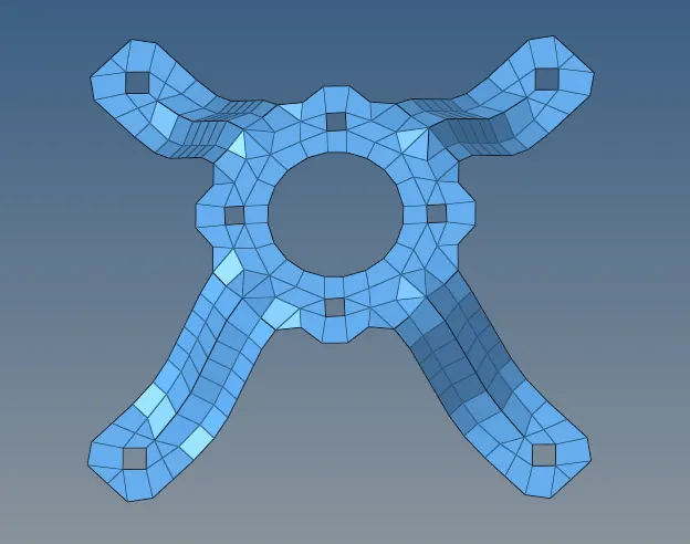
Fig.27 Mid Surface Meshed.
Since the Part-3 Model looks Symmetrical and rotated, the mesh is copied and rotated to the other side using the TOOLS – ROTATE option.

Fig. 28 Rotate Option.
Quality Checks:
After mid-surface meshed, quality checks have to be performed and the mesh should be free from quality errors. Figure 29 shows the Quality Criteria set for the given model.
Fig.29 Quality Criteria Check.
The quality check was performed and quality errors were cleared. The mesh model free from quality error is shown the figure 30.
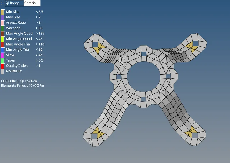
Fig.30 Quality Checks performed on the mesh.
After clearing all the quality issues, elements normals were checked using the NORMAL option from the TOOL menu.
Assigning Thickness: The model has been provided with respective properties namely Thickness, Material, Name, and Ids. Finally, the elements were drawn as solids. The mesh elements of the entire model are drawn as 2D DETAILED ELEMENT REPRESENTATION to reflect the actual CAD geometry. Figure 32 shows the final model along with CAD Geometry.
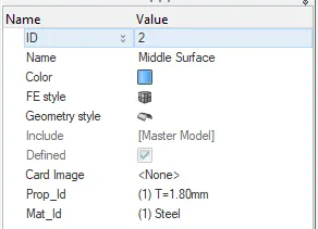
Fig.31 Thickness Property assigned.
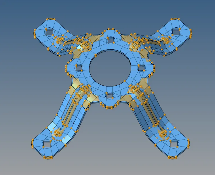
Fig.32 Final Part-2 Model.
Results:
The Mid-surface was successfully extracted from the CAD after clearing all the topological errors and well as the mid-surface errors. The given model has been cleared for geometrical errors and meshed for the specified mesh criteria.