Assignment 1-2D Meshing Challenge
AIM: To Generate the midsurface for the given component and mesh the component with given quality critera and mesh parameters.
PROCEDURE:
Step1: To import the given component into the gui
- File Menu>import>Model>Select the file>Import.
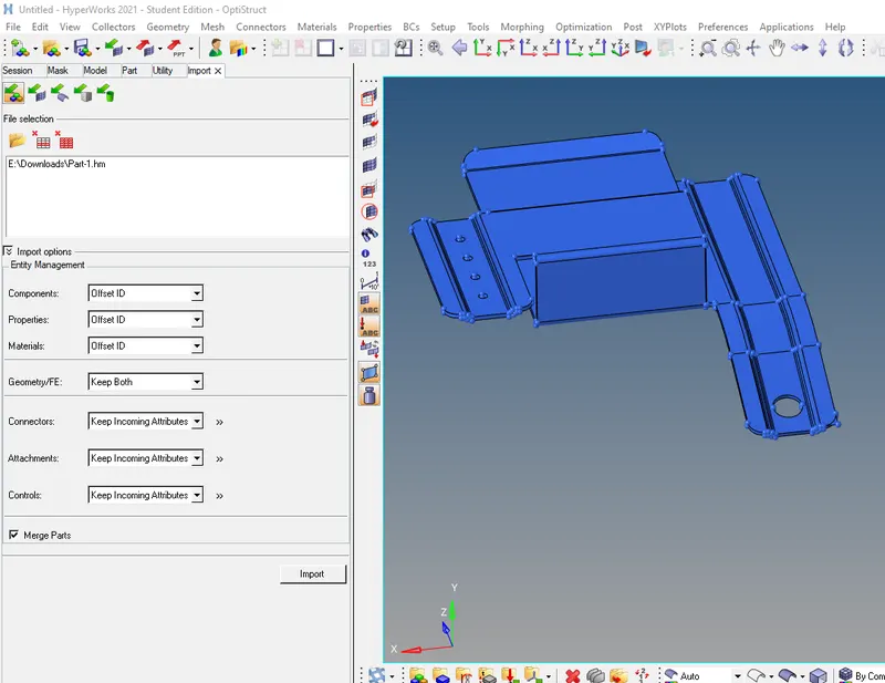
Step2: To perform the geometry clean up for the given component
- Switching to topo mode to check for geometry.
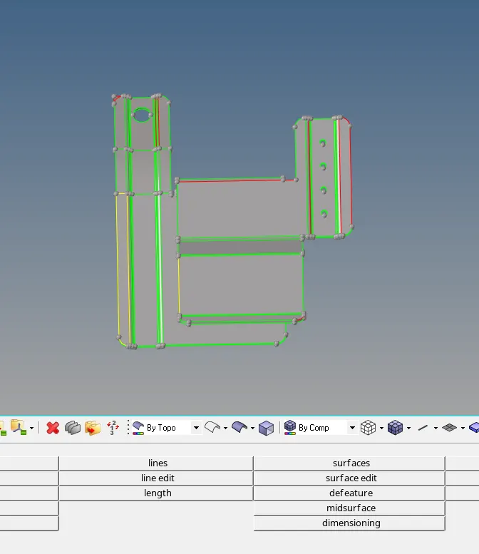
- To fix incomplete geometry or open surface
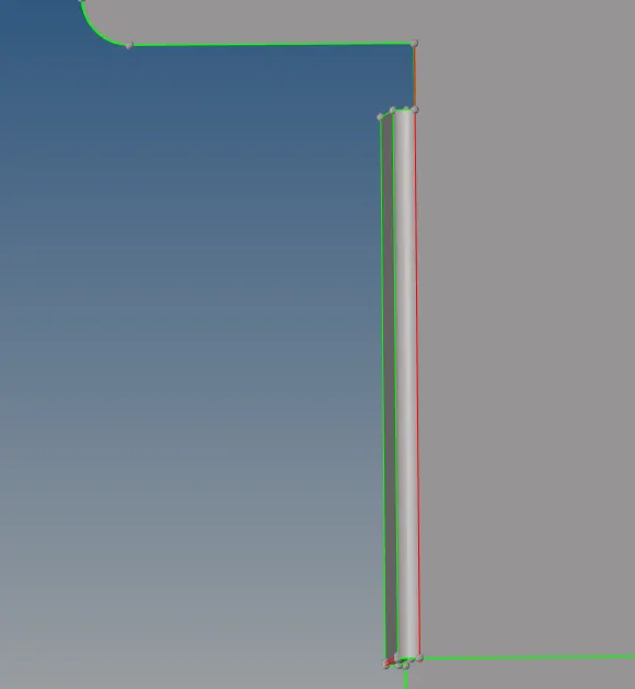
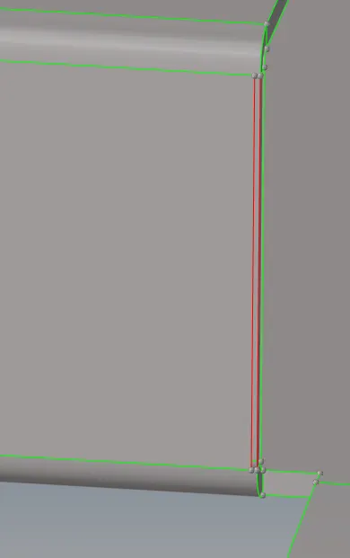
- The above image shows that the edge is not shared or attached to the adjacent surface which is indicated in red color which is a single con.
- Now to fix the above surfce using toggle option to combine or stich the 2 surface together, now the con is indicated in the green line.
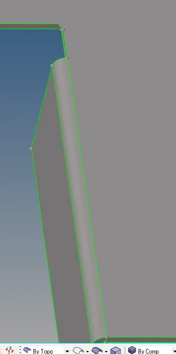
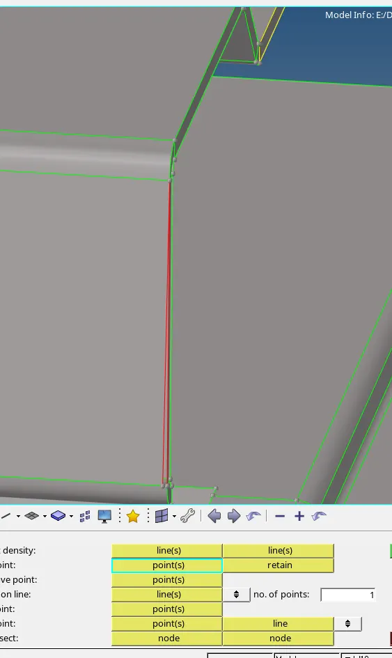
- To fix the below open surface as shown in below image.
- Using replace point option to fix the surface.
- F11 selecting the point to replace.
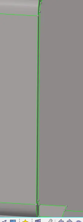
- `Now the surface has been fixed and closed.
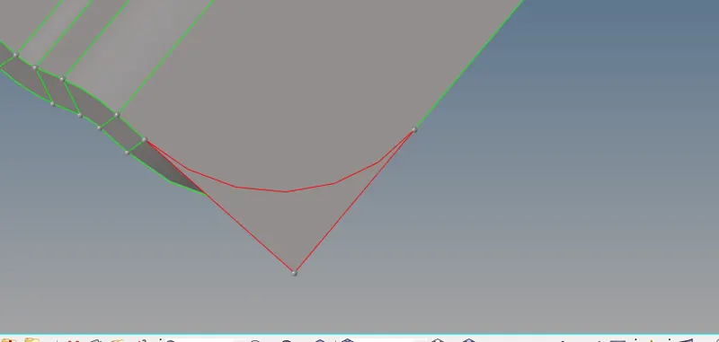
- Now to fix above protruding surface
- using split by face to delete the protruding surface.
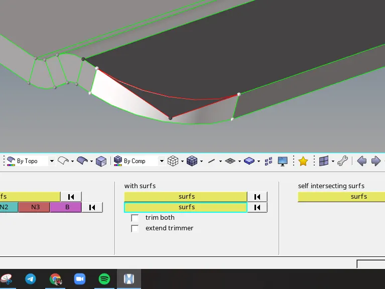
- Shift F9 or Geom>surface edit seleting 2 surface.
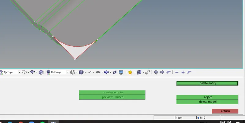
- F2 or using delete surface option to delete the protruding surface.
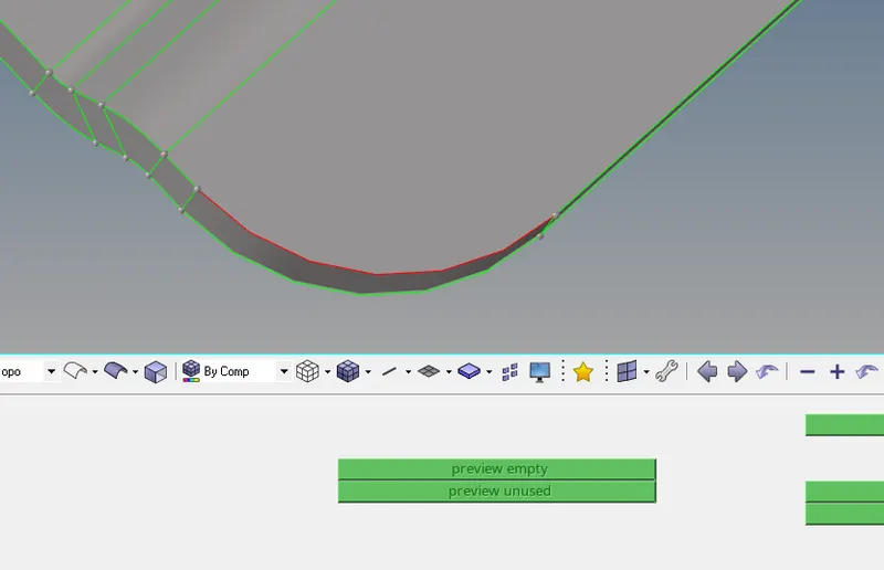
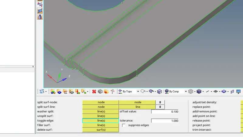
- Using toggle option to stitch the surface.
- To delete the duplicate surface .
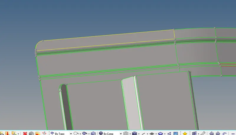
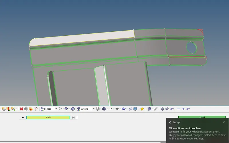
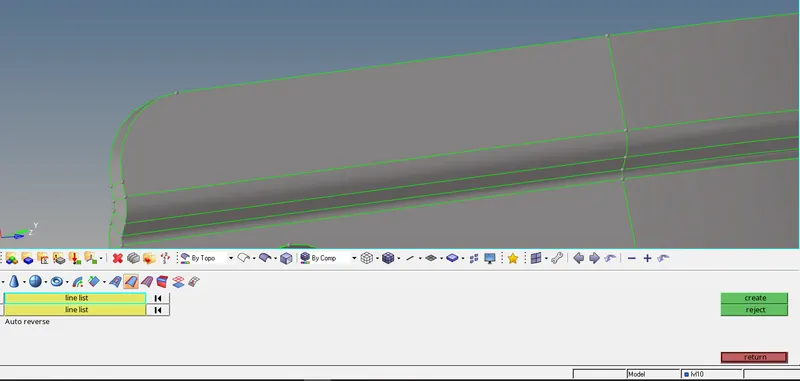
- F2 or using delete surface option to delete the duplicate surface.
- Now the geometry is fixed.
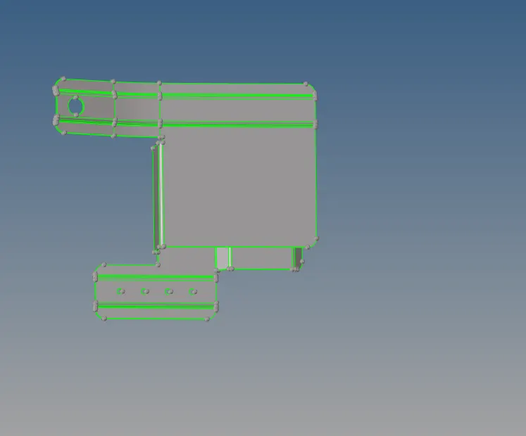
Step3: To prepare the component for meshing to avoid element failure also to get the better mesh by using defeaturing.
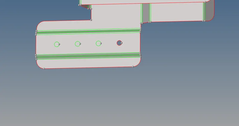
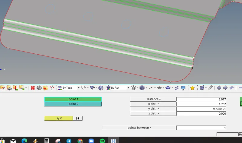
- Now measuring the fillet region using distance option.
- The fillet distance is less than minimum size of the element.
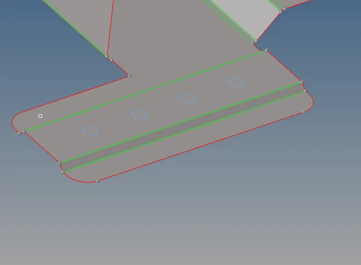
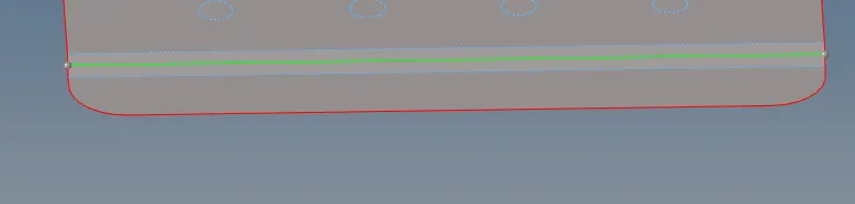
- Using defeature options to remove the fillet
- And create the middle line in the fillet region.
- Filling the holes which is less than 5 units in dia.
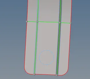
- F11 or quick edit to fill the hole. geom>quick edit>filler.
Step4: To mesh the given component with given parameter.
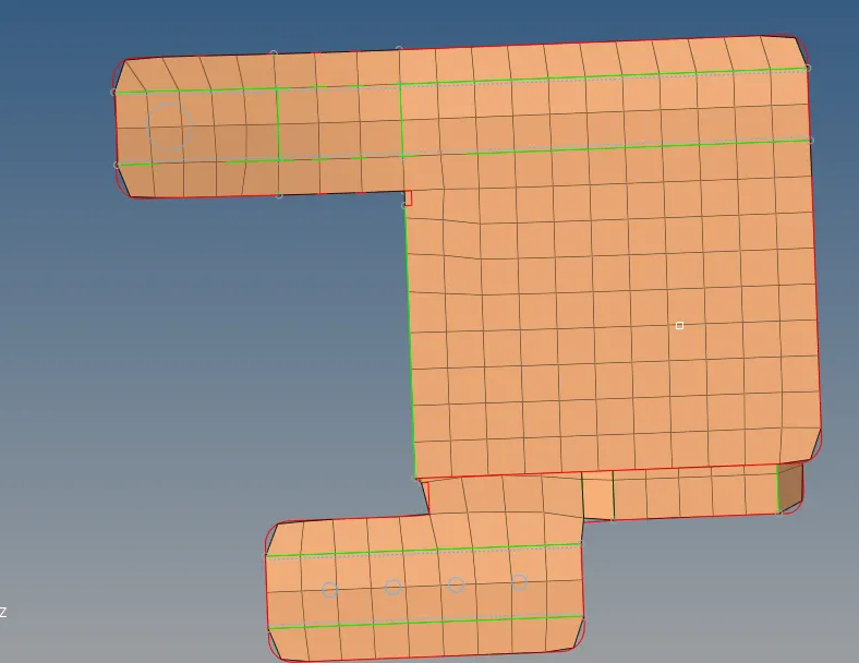
- F12 or 2d>automesh>selecting the surface.
- Selecting the element size>mesh.
Step5: To fix the quality of the element
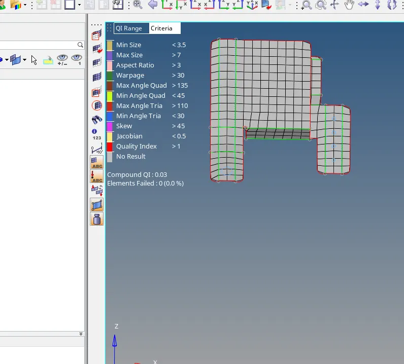
- Using distance option orF4 to remove the minimum and maximum quality by moving the node accordingly
- Used element optimization from element clean up tool.
- fixed the quality.
Step6: To check for the conectivity issues.
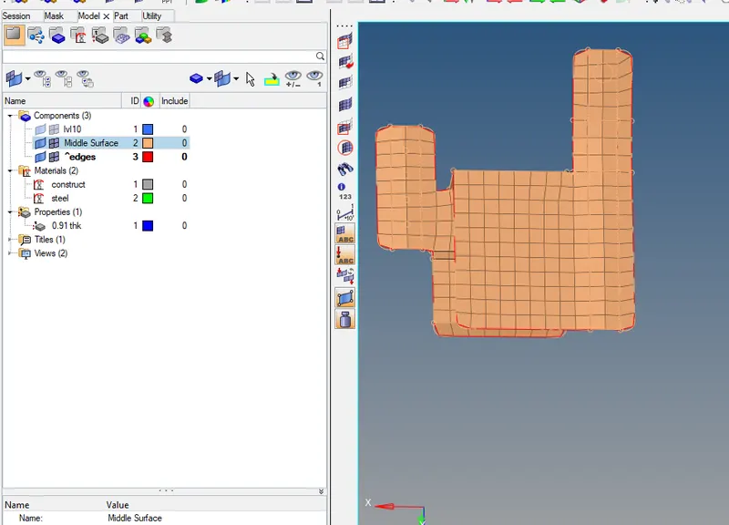
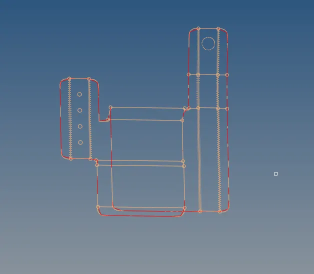
- Shift F3 or Tool> edges option and provide tolerance
- The free edges are highligted in red colour.
- Using equivalence option to connect the edges.
Step7: To Assign the property and materials for the given component.
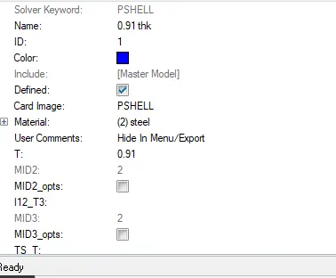
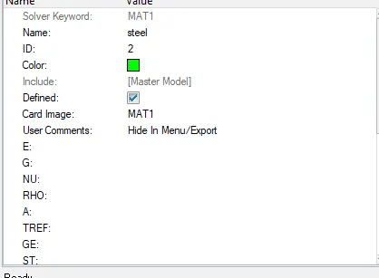
- Right click on the menu bowser and select create
- By giving the thickness to the property
- Also selecting the material cards
- Now right clicking on the components>Assign>selecting the property.
- The material and property is assigned to that component.
Following the same procedure for the other given components.
Final Pictures of the given models:
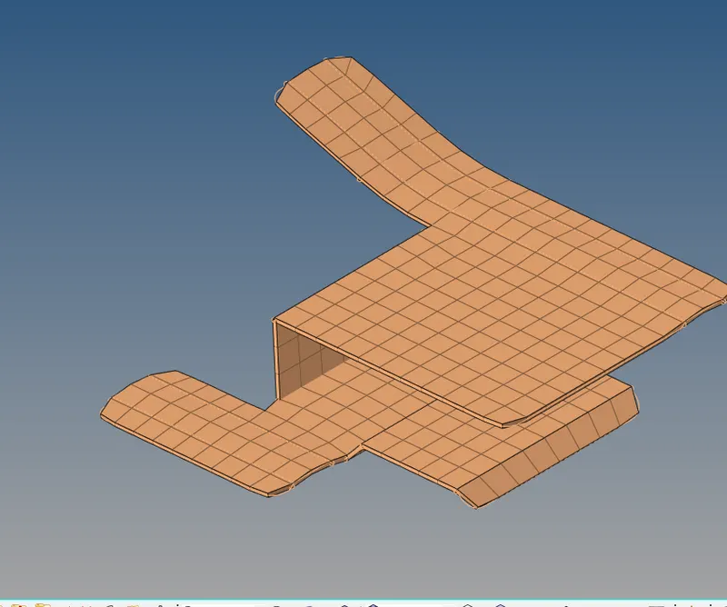
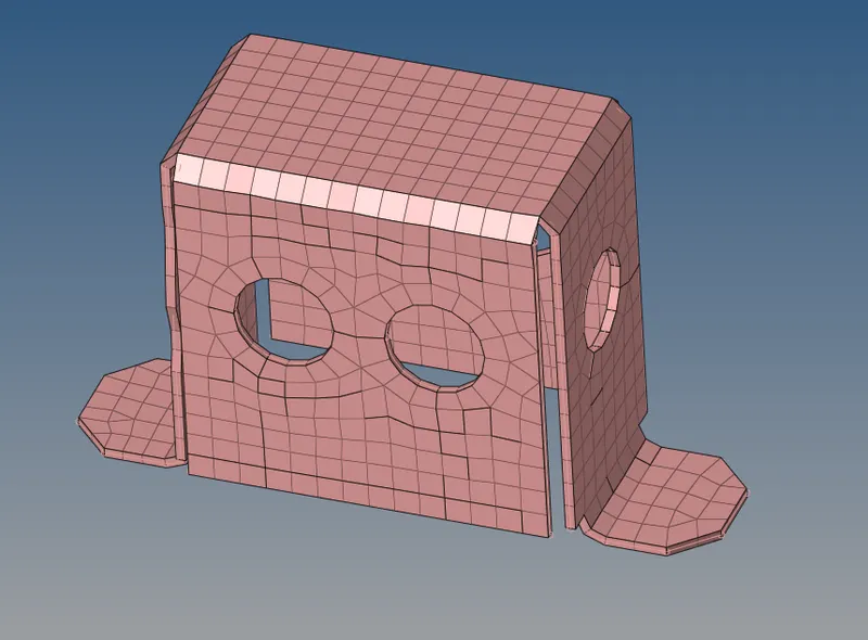
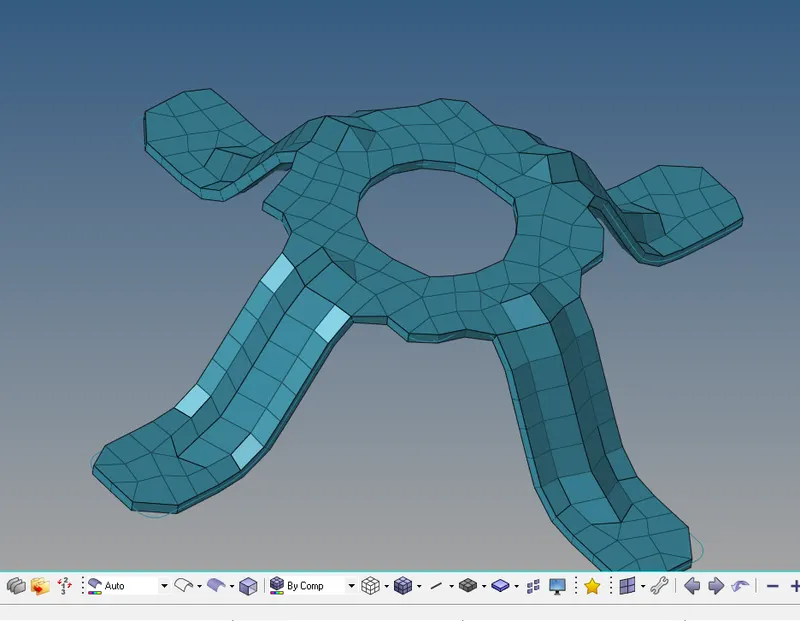
1 2 3
RESULT: Successfully Created the midsurface and meshed all the 3 given component with given quality criteria and mesh parameters.