Assignment 1-2D Meshing Challenge
AIM :
To Mesh the given plastic component and assign the variable thickness to different parts in the component.
GIVEN COMPONENTS :
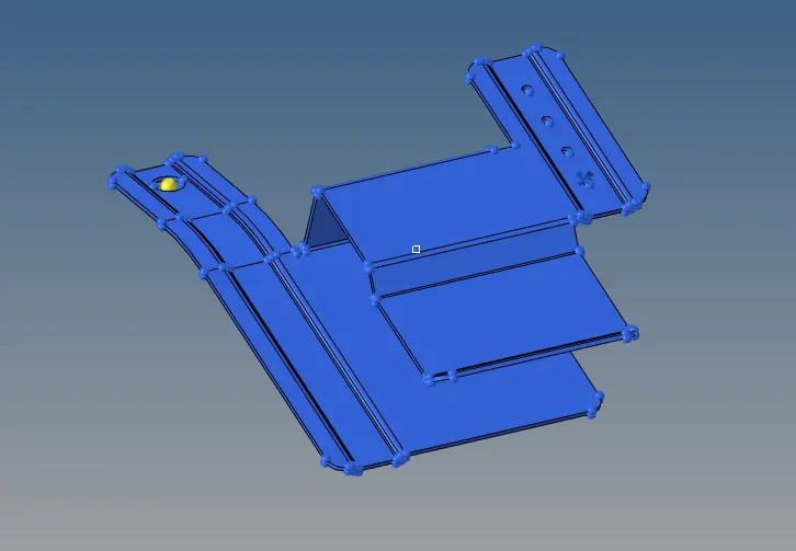
COMPONENT 1
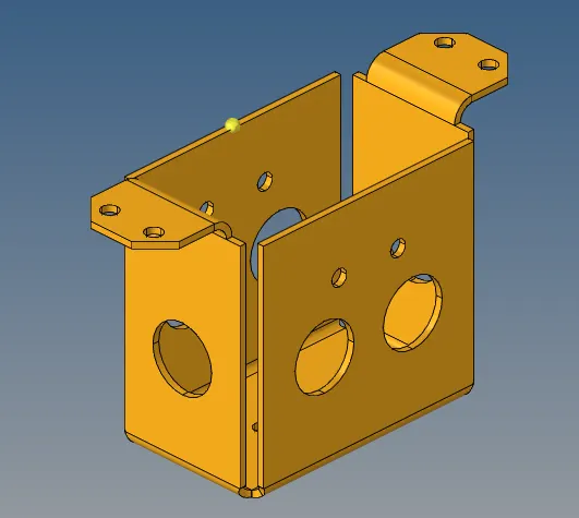
COMPONENT 2
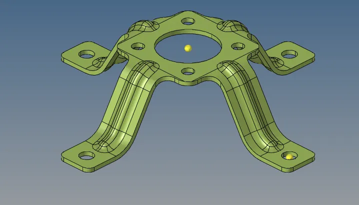
COMPONENT 3
PROCEDURE FOR COMPONENT 1
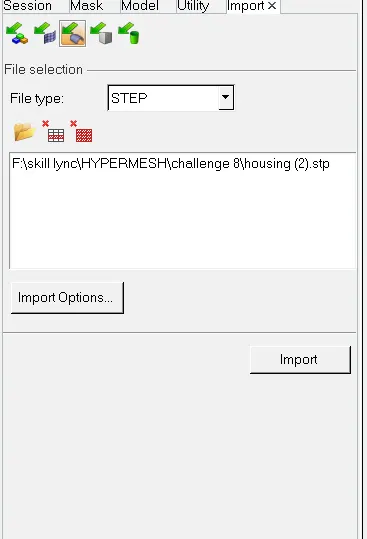
Step 1: IMPORTING THE GEOMETRY
Importing the geometry of the given model as HYPER MESH file by using the tool as import geometry.
STEP 2: CHANGING THE MODE
- Change the color geometry mode from Auto to By Topo
- We select the By topo method because it is the handy option that is used to identify the free edges, shared edges, T-Junction, and Suppressed edge. Now, clean up the solid part If any present in the Geometry
- This also helps to find out the surface and solid in the components
STEP 3: SURFACE CLEANUP
- Always do the manual cleanup for the component. To do this press F11 or Go to Cleanup Tools
- In this menu, you can perform various operations like Toggle, split, washer split, etc based on the cleanup required for the given component.

- Final parent component after doing all surface cleanup
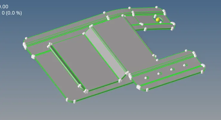
STEP 4: MIDSURFACE EXTRACTION
- Now, we need to extract the mid surface one by one by manual or by auto mid command under Geometry
- For this mid surface, I use the OFFSET command.
- Before offsetting the surface, create a new collector for saving the mid surface for the current component
- And make this collector a current component
- Now measure the distance between the two surfaces
- Then go to the OFFSET feature in the surface edit command
- Select the surface that you want to offset and make it a duplicate
- Repeat the same process for all surfaces in the components
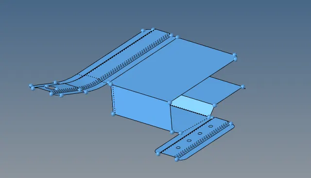
STEP 5: CLEANUP PROCESS IN MID SURFACE
- After taking the mid surface, we need to do a cleanup process for meshing
- Toggle the lines when they fall below the Minimum length criteria.
- In this below case, the distance between two points is 2.02, but our minimum length is 3.5mm
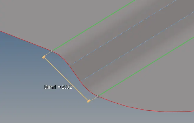
- so we try to toggle one of the lines for preventing the element from a minimum length
- Fill the holes by using the filler surface command in the Quick edit panel.
- And finally, it looks like the image shown below
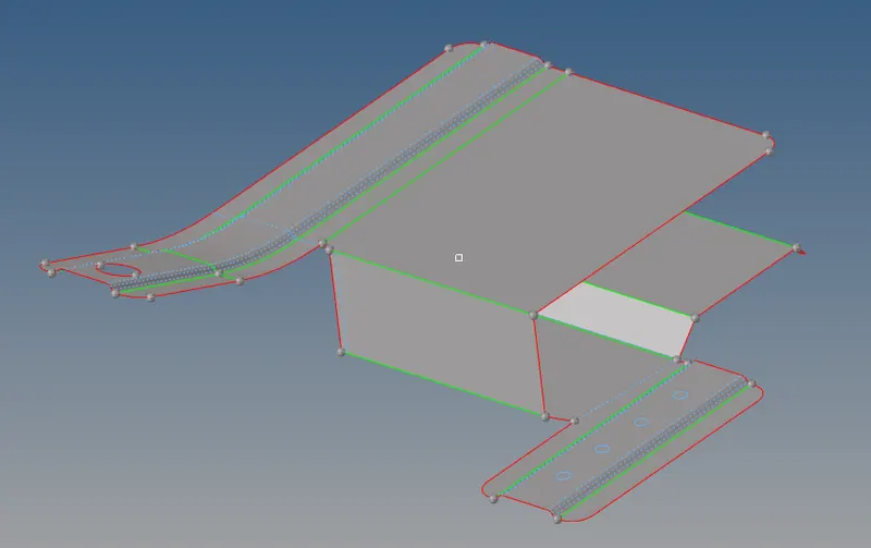
- And green line indicates the intersection of two surfaces
- And red line indicates the free edges
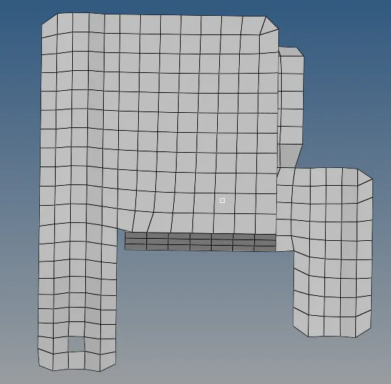
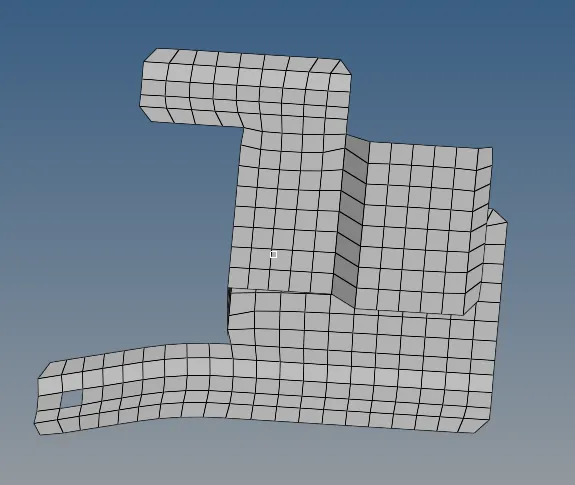
STEP 6: MESHING
- Meshing is a part of the simulation process where complex geometries are divided into simple elements that can be used as discrete local approximations of the larger domain.
- The mesh influences the accuracy, convergence, and speed of the simulation.
- Click the F12 or select the auto mesh option in the geometry menu.
- Auto mesh option is used for meshing a surface with 2D elements
- Change Geom mode as 2D in the Mainmenu bar
- Then select the Automesh option
STEP 7: QUALITY CHECKUP
- clean the minimum and maximum length failing elements.
- Also clear the warpage, aspect, taper, etc
- For the cleanup of the element failing, use the QUALITY INDEX feature
- If any element has failed, remesh it or use the replace option

STEP 8: CHECK THE FREE EDGES BETWEEN THE ELEMENT
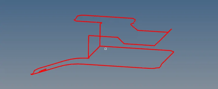
- After meshing, we have to check the edges between the elements
- If you have any edges between the elements, use the equivalence option to fix this issue
- And we can also use the replace option
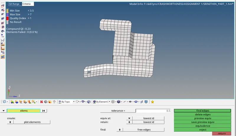
- After clearing the connectivity of the elements, check for free edges by using the FING EDGES option
STEP 09: CHECK DUPLICATES
- After doing the above steps, now we have to check for the duplicates of elements present in our model.
- For that click the duplicates under the Quality criteria option.

If there are any duplicates found, then save those elements and delete those items by using the retrieve option in the delete command
STEP 10: ASSIGN THE PROPERTY & MATERIAL
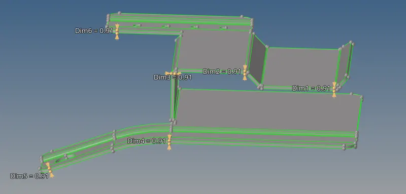
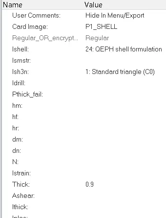
- Measure the thickness for the parent component
- Then create the property collector and assign the individual thickness
- And assign the property to the component collector
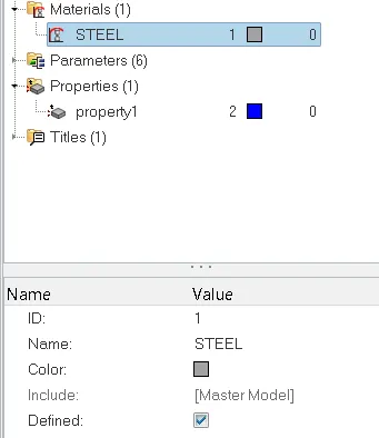
FINAL COMPONENT
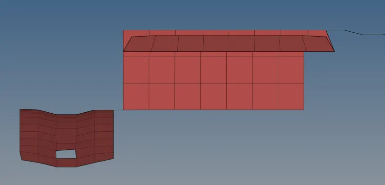
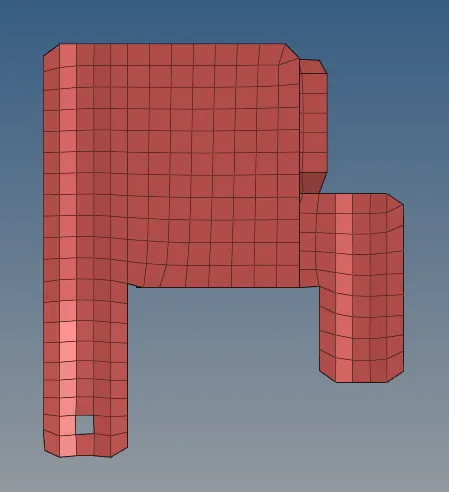
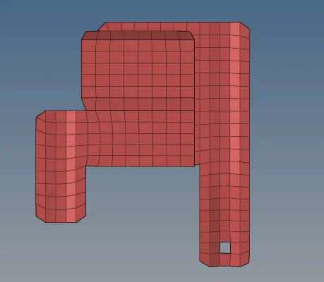
PROCEDURE FOR COMPONENT 2
All steps are common for this 2nd component, but in this component, we use the REFLECT command.
STEP 11: USING REFLECT
- To reduce the time for meshing the identical component, we use the reflect command.
- For using the reflect option, we have to mesah the one side of the component.
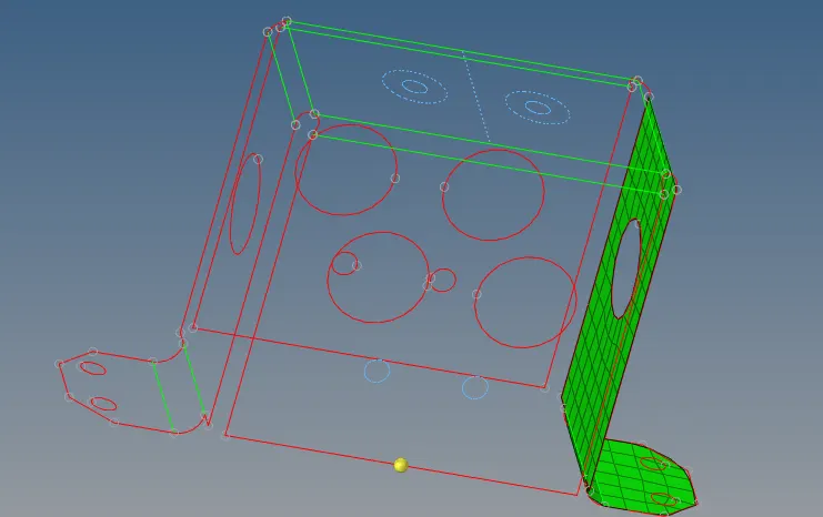
- In this above, both sides are identical, so we mesh the one side of the component
- And to reflect, we need to create the center point by using the measure command
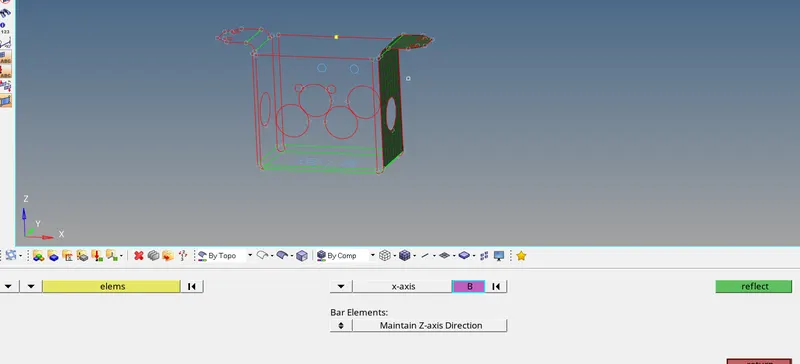
- Now select the elements that need to reflect and reflect to the x-axis and select the center point as the base point
- Now duplicate the elements to the current component and click the reflect button.
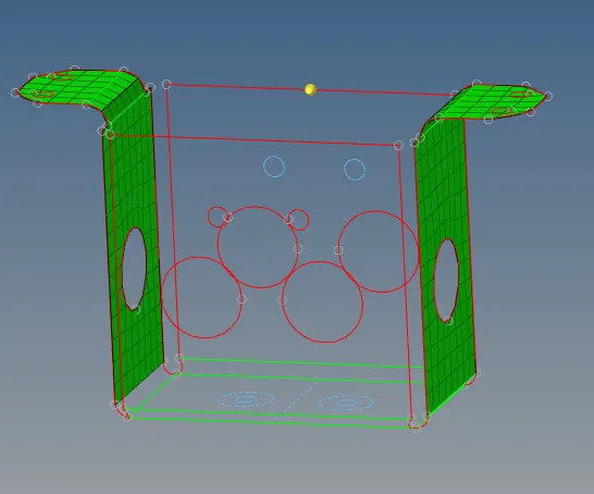
- Do the same process of reflecting for another side's identical faces to reduce our meshing time.
- And do the same steps that we followed in component 1.
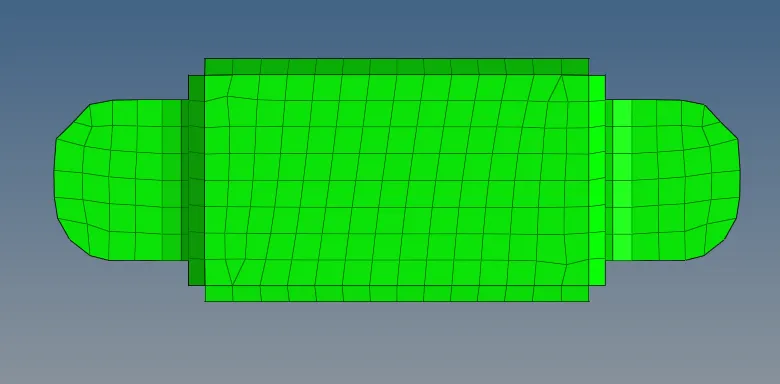
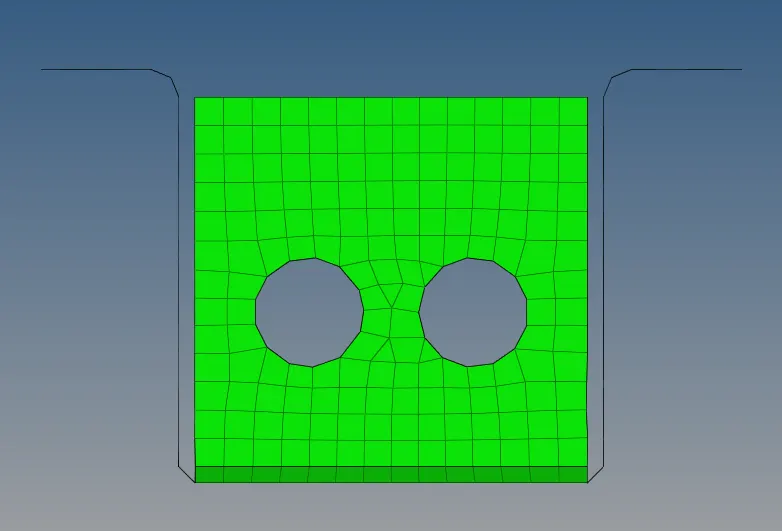
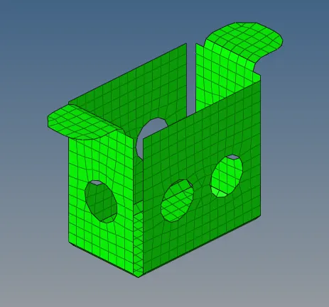
FINAL 2ND COMPONENT
PROCEDURE FOR COMPONENT 3
All steps are common for this 3rd component as previous components , but in this component, we use the ROTATE command.
STEP 11: USING ROTATE
- To reduce the time for meshing the identical component, we use the Rotate command.
- For using the ROTATE option, we have to mesh one side of the component.
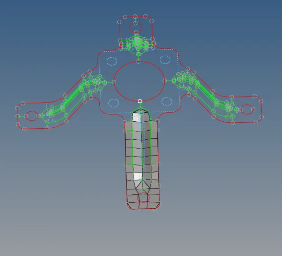
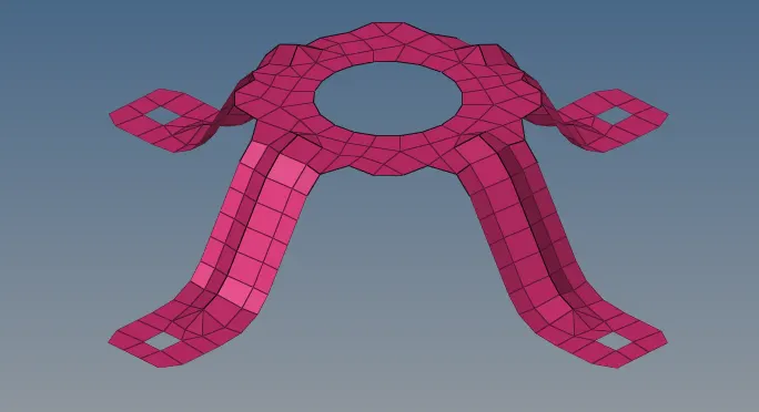
- In this above, Four legs are identical, so we mesh the one side of the component
- And to ROTATE, we need to create the center point by using the measure command
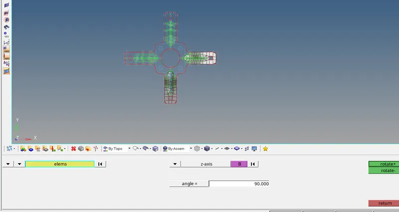
- Now select the elements that need to reflect and reflect on the x-axis and select the center point as the base point
- Now duplicate the elements to the current component and click the reflect button.
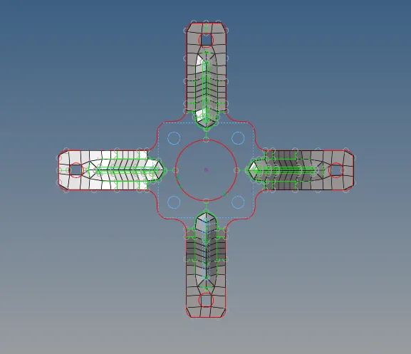
- Do the same process of reflecting for another side's identical faces to reduce our meshing time.
- And do the same steps that we followed in component 1.
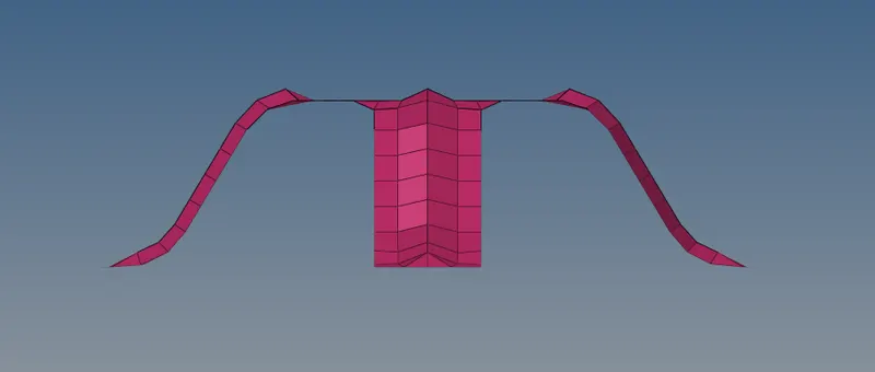
FINAL 3rd COMPONENT
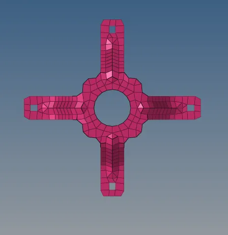
RESULT :
Thus the given components is meshed under the given quality criteria and assigned the thickness for the individual components