Assignment 1
OBJECTIVE
The main objective of this challange is to do the following for the given model.
- Clean the geometry.
- Extract midsurface.
- Clean midsurface geometry.
- Create 2D mesh with target length 5mm, min 3.5mm max 7mm.
- And assign proper thickness, by creating a generic property.
PROCEDURE:
MODEL 1 :
STEP1) Do check for the presence of solids in the model, if any delete the same using delete option.
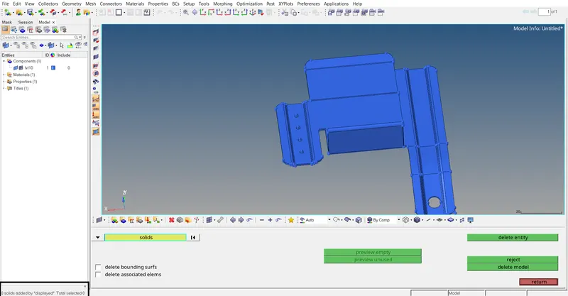
Figure 1. SOLID DELETION RPRESENTATION
STEP 2) Change to Topo MODE & Clean the parent geometry at the highlighted one to get the neat model.
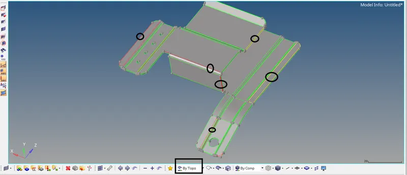
Figure 2. FREE EDGE & OVERLAPPING OF SURFACE RPRESENTATION
2.1) Tools used to clean the geometry are: Toggle edge, Filler surf surface trim.
STEP 3) The next step is to generate midsurface for the model. Use Geom > midsurface option.

Figure 3. Geom PANEL RPRESENTATION
STEP 4) Select and right click the surfs option and select displayed option to select the entire surface at one shot.


Figure 4. MIDSURFACE PANEL RPRESENTATION Figure 5. AFTER RIGHT CLICKING ON SURFS OPTION
STEP 5) Clean up the geometry according to the given size of the element so that the mesh will not fail for min quality criteria.
5.1) Tools used to clean the geometry are: Toggle edge, Filler surf.
5.2) The hole highlighletd have been filled advertently since they are less than 5mm in dia and the hole have been filled with surface using filler surf option from quick edit panel or F11 button.
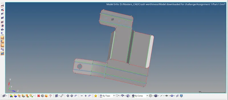
Figure 6.MIDSURFACE REPRESENTATION
STEP 6) After craeting midsurface next is to start meshing with shell elements. Use 2D > automesh or F12 button.

Figure 7. 2D PANEL REPRESENTATION
STEP 7) To give quality criteria use Preferences > Criteria file settings and input the given criteria (Min & Max size 3.5mm & 7mm respectively)
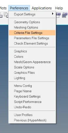
Figure 8. CRITERIA FILE SETTING
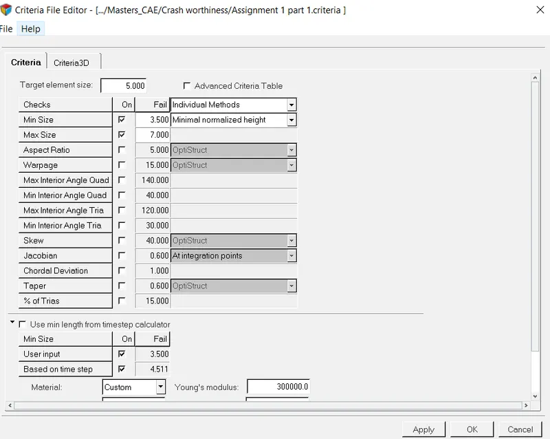
FIGURE 9. QUALITY CRITERIA
STEP 8) Mesh the model surface by surface so that we can have a cotrol over the quality criteria. Choose Target element size as 5mm.
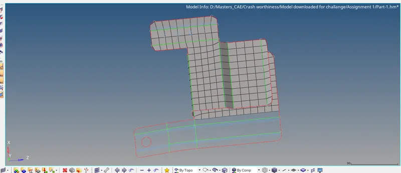
FIGURE 10. MESHING REPRESENTATION
STEP 9) The below image represents the quality settings for the meshed elements. Failed elements is kept as it as, since it affects feature capturing.
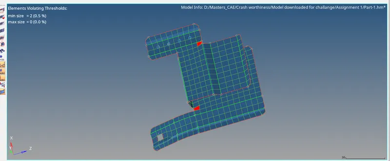
FIGURE 11. QUALITY CRITERIA
STEP 10) The next step is assign the elements their thickness, taken from the parent geometry.
10.1) Right click on the tool bar and create property to assign thickness.
10.2) Rename the property collector to Thickness 1
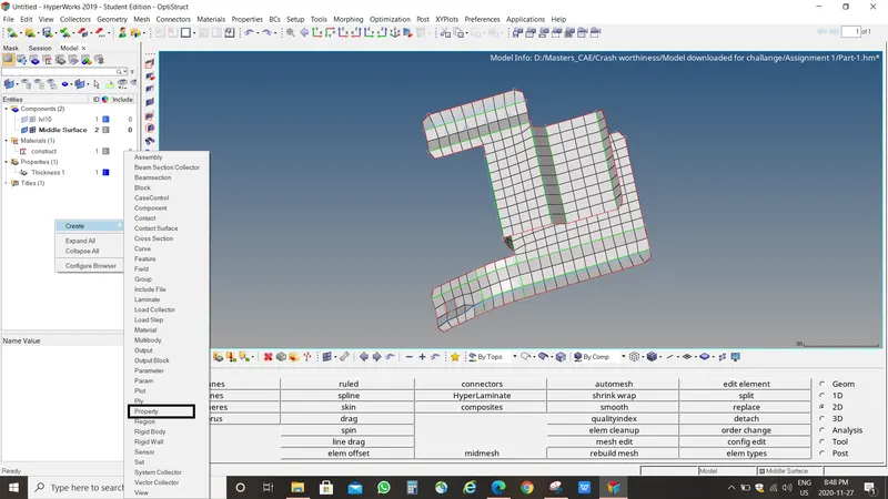
FIGURE 12. PROPERTY ASSIGNATION REPRESENTATION
STEP 11) Update the card image to PSHELL since they are 2D elements & and give thickness as 1mm ( taken from parent geometry).
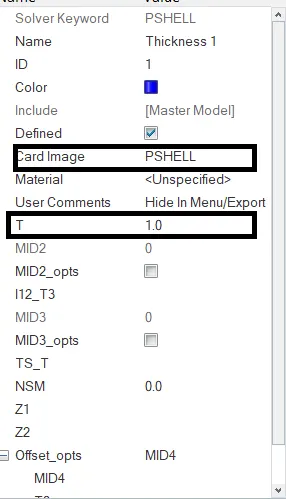
FIGURE 13. THICKNESS ASSIGNATION REPRESENTATION
The below image shows the model with the assigned thickness. Select 2D detailed Element representation to represent the the shell elements with their assigned thickness.
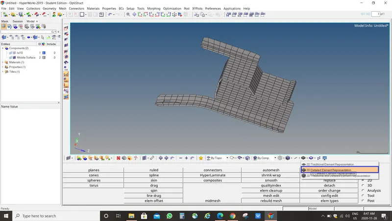
FIGURE 14. 2D DETAILED ELEMENT REPRESENTATION
MODEL- 2:
STEP 1) Check for the presence of solids in the model, if any delete the same using delete option.
STEP 2) Extract the midsurface of the Clip repair using auto midsurface option. Use Geom> midsurface.
STEP 3) Right click in the surf button and select displayed option to select the surfaces for midsurface extraction.
Figure 15. MIDSURFACE PANEL RPRESENTATION Figure 16. AFTER RIGHT CLICKING ON SURFS OPTION
STEP 4) Delete the shown temp nodes which are in default in the model. To acheive this use Geom > Temp nodes.
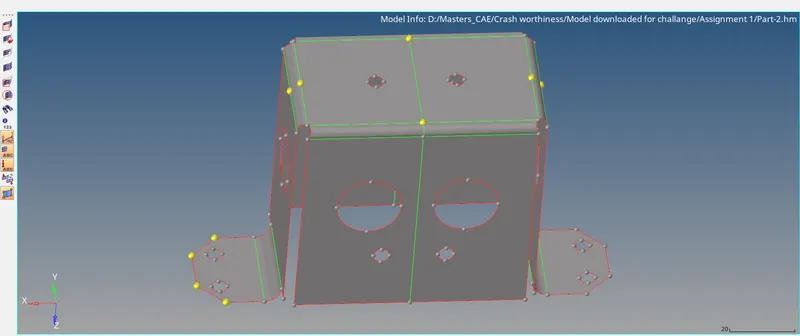
Figure 17. MIDURFACE REPRESENTATION
4.1) Select the nodes which are to be cleared and simply hit clear option.

Figure 18. TEMP NODES PANEL REPRESENTATION
STEP 5) To give quality criteria use Preferences > Criteria file settings and input the given criteria (Min & Max size 3.5mm & 7mm respectively)
Figure 19. CRITERIA FILE SETTING
FIGURE 20. QUALITY CRITERIA
STEP 6) Mesh the model by surface by surface individually.
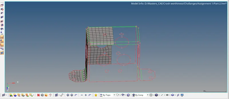
Figure 21. MESH REPRESENTATION
STEP 7) For the mesh near hole, to get proper mesh use Tool > Rotate option. Select the nodes around the hole mesh.
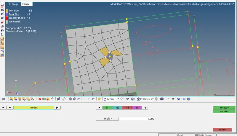
Figure 22. ROTATE PANEL REPRESENTATION
STEP 8) Also define the plane (N1, N2, N3) at which the mesh should be corrected and give the base node highlighted at center of the hole.
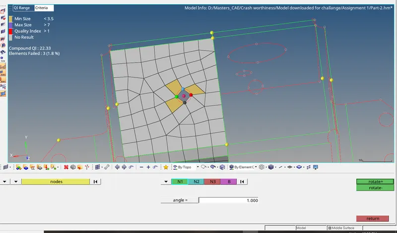
Figure 23. ROTATE PANEL REPRESENTATION
STEP 9) After meshing one half of the the model, since they are symmetric we can reflect the mesh to other surface.
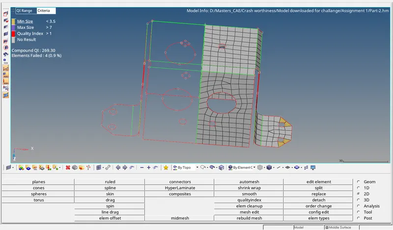
Figure 24. MESH AT ONE HALF REPRESENTATION
STEP 10) Select the node N1 and N2 between which the center node have to selected. Select the node between option which gives center node ( Yellow), behaves as base node for the reflection operation to be performed.
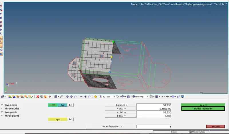
Figure 25. BASE NODE REPRESENTATION
STEP 11) Select the elements displayed, duplicate them and select the appropriate axis ( X axis ). Simply select reflect option to reflect the mesh.
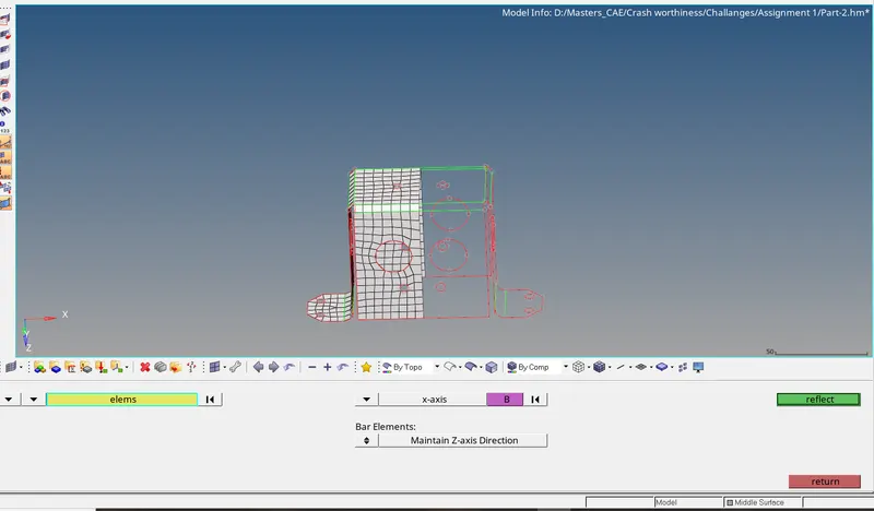
Figure 26. REFLECT PANEL REPRESENTATION
STEP 12) After reflecting check for equivalence of the model. For this use shortcut Shift+F3.
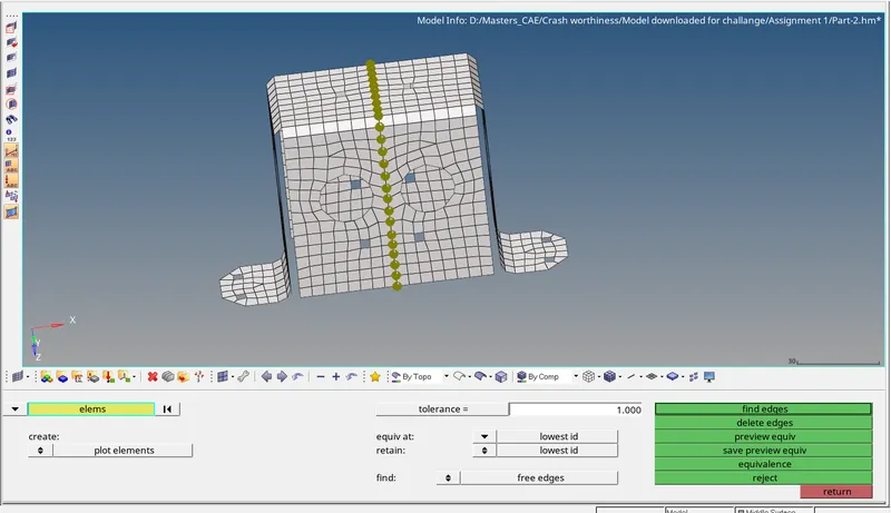
Figure 27. EDGE PANEL REPRESENTATION
STEP 13) The below image represents the qaulity criteria of the model. The failing elements are left as it is, to highlight feature capturing.
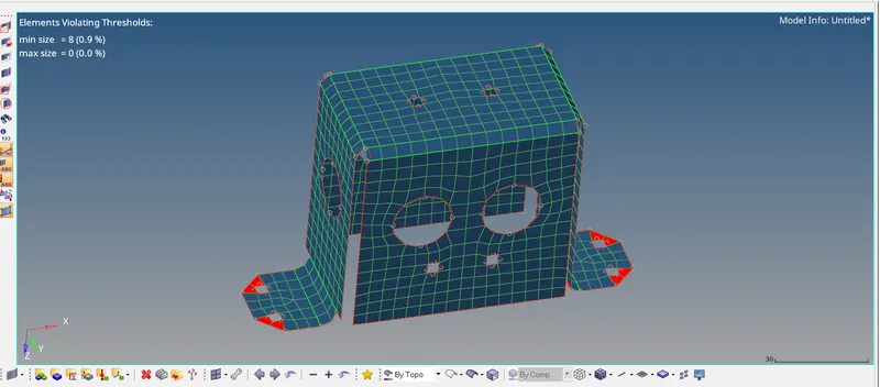
FIGURE 28. QUALITY CRITERIA
STEP 14) To give thickness right click on the tool bar and create property to assign thickness & rename the property collector to T 2.
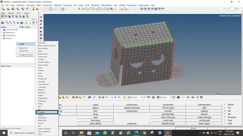
FIGURE 29. PROPERTY CREATION
STEP 15) Update the card image to PSHELL since they are 2D elements & and give thickness as 2mm ( taken from parent geometry).
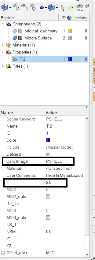
FIGURE 30. THICKNESS ASSIGNATION
The below image shows the model with the assigned thickness. Select 2D detailed Element representation to represent the the shell elements with their assigned thickness.
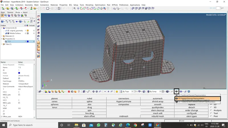
FIGURE 31. 2D DETAILED ELEMENT REPRESENTATION
MODEL- 3:
STEP1) Do check for the presence of solids in the model, if any delete the same using delete option.
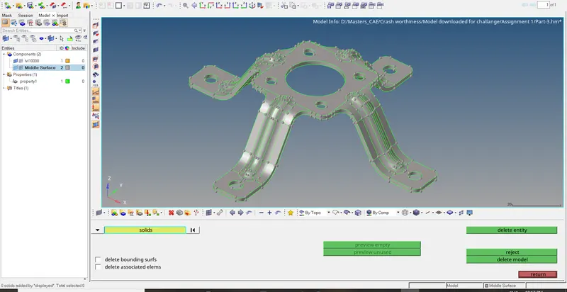
FIGURE 32. SOLID DELETION RPRESENTATION
STEP 2) The next step is to generate midsurface for the model. Use Geom > midsurface option.
Figure 33. Geom PANEL RPRESENTATION
STEP 4) Select and right click the surfs option and select displayed option to select the entire surface at one shot.
Figure 34. MIDSURFACE PANEL RPRESENTATION Figure 35. AFTER RIGHT CLICKING ON SURFS OPTION
STEP 5) Clean up the midsurface according to the given size of the element & tools used to clean the geometry are: Toggle edge.
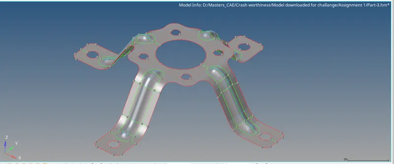
Figure 36. MIDSURFAE REPRESENTATION
STEP 6) After craeting midsurface next is to start meshing with shell elements of size 5mm. Use 2D > automesh or F12 button.
Figure 37. 2D PANEL REPRESENTATION
STEP 7) To give quality criteria use Preferences > Criteria file settings and input the given criteria (Min & Max size 3.5mm & 7mm respectively)
Figure 38. CRITERIA FILE SETTING
FIGURE 39. QUALITY CRITERIA
STEP 8) Mesh the model surface by surface so that we can have a cotrol over the quality criteria. Choose Target element size as 5mm.
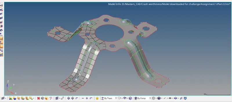
FIGURE 40. MESHING REPRESENTATION
STEP 9) After meshinfg the entire mounting bracket, check for quality.
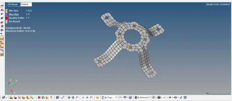
FIGURE 41. QUALITY CRITERIA
The next step is assign the elements their thickness, taken from the parent geometry.
9.1) Right click on the tool bar and create property to assign thickness.
9.2) Rename the property collector to Thickness 1
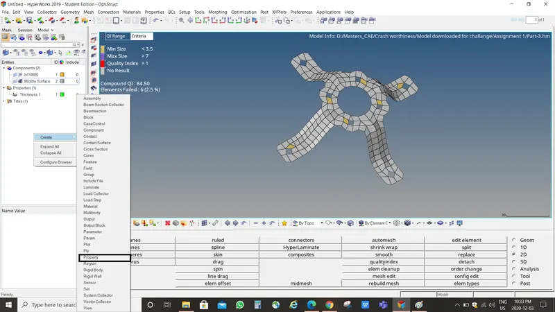
FIGURE 42. PROPERTY ASSIGNATION REPRESENTATION
STEP 10) Update the card image to PSHELL since they are 2D elements & and give thickness as 1.8 mm ( taken from parent geometry).
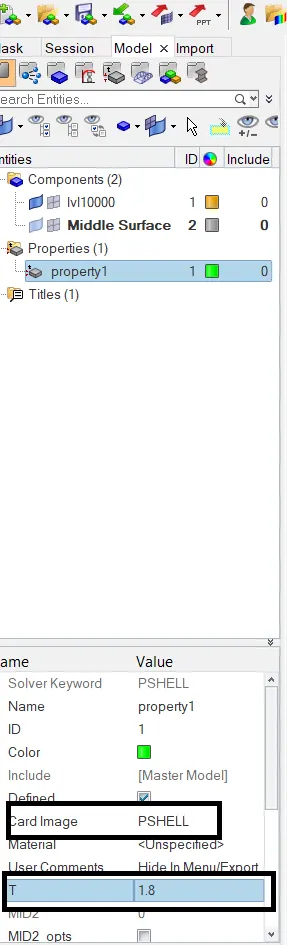
FIGURE 43. THICKNESS ASSIGNATION REPRESENTATION
STEP 10) The next process is to represent hte meshed model in 2D form by using Detailled representation option.
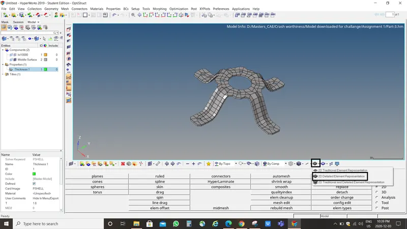
FIGURE 44. 2D DETAILED ELEMENT REPRESENTATION