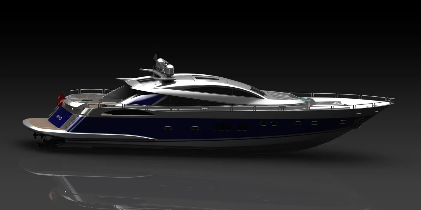
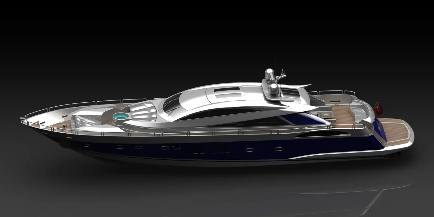
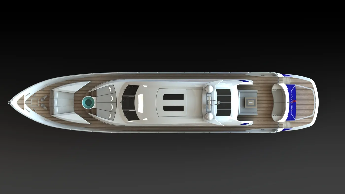
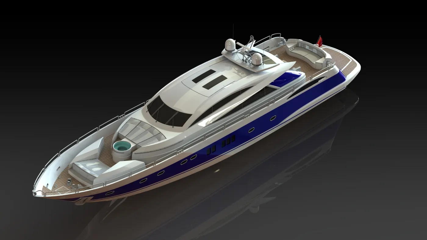
Assembly of Yacht
Report on Sunseeker Predator YACHT
Objective: - To assemble and model the Sunseeker Predator YACHT in SolidWorks.
Introduction: -
All the parts are created with accurate dimensions
Parts created in this Project.
- Propeller.
- Radar.
- Setting up the BLUE PRINTS.
- Hull.
- Garage Door.
- Front Seat .
- Middle Seat.
- Rear Seat.
- Superstructure.
- Assembly of Yacht.
Description of features used: -
Sketch: - sketch is the basic drawing or we can say a 2d structure which is used for further creation of the model.
Boss Extrude: - Boss extrude is a tool used to create a 2D closed shape into 3D shape.
Revolve: - A particular sketch is extruded around a specific axis which is called as axis of rotation.
Revolve Cut: - A particular sketch is used to give a extruded Cut around a specific axis which is called as axis of rotation.
Extrude cut: - It is used to cut a 3D shape like cutting holes, slots etc.
Fillets: - Filets are given to the sharp edges of a 3D model to give it a round profile.
Chamfer: - It is used to give a tapered look to the model or we can say chamfered look.
Combine: - Used to combine to independent bodies and make them a whole single solid body
Projected Curves: - It is used to create a curve in the 3D space from two Curves which intersects each other and make a curve at the intersection which is known as a Projected Curve.
Reference Plane: - This tool is used to create a plane in the 3D space.
Split: - The Split feature is used to split the sections from a solid body with the help of a 2D drawing.
Trim: - to remove the unwanted section of a drawing.
Pattern: - there are many types of Patterns available like Linear, Circular and Rectangular.
Mirror: - To mirror the drawing or a solid body about any structure.
Convert entities: - This feature is used to get the drawing from any solid body.
Move/Copy Body: - To move or copy the body.
Dome: - It creates a Dome like structure to part face.
Offset: - This feature creates the same drawing at the specified distance from the original sketch.
Sweep Surface: - Sweep Surfaces are surfaces that are generated from a section curve positioned along a path
Loft Surface: - Loft Surfaces are surfaces generated by multiple 3D Curves or existing edges creating a smooth tangency between the selected curves.
Fill surface: - These are surfaces created by any boundary sketch or shape.
Surface trim: - It is used to Trim any surface and also to cut any surface into 2 or more parts.
Surface knit: - It is used to merge or combine two or more surfaces into one.
Sweep cut: Creates a sweep by moving a 2D profile along a 2D or 3D sketch path.
etc.
Description of the making process of the Parts of the YATCH.
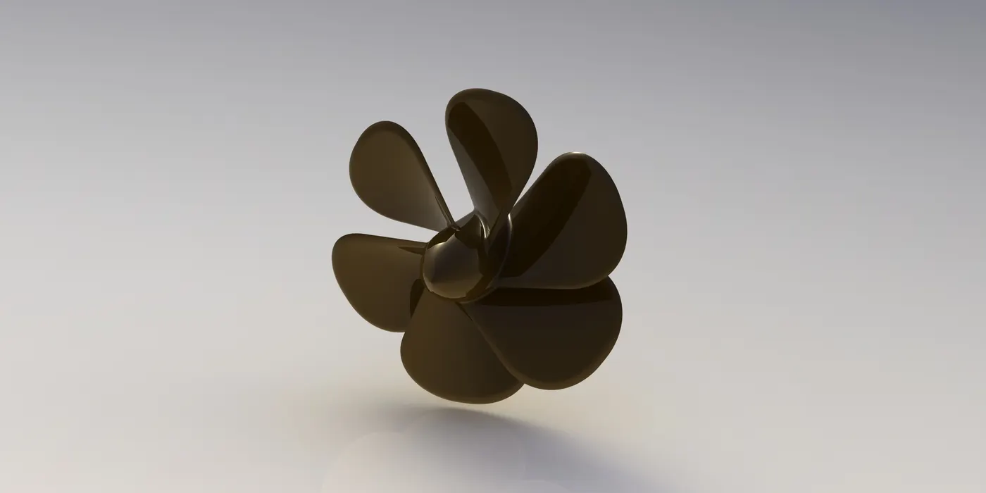
- Propeller –
Revolve of a sketch is done in the starting and then a reference plane is given, then a loft feature is used between two sketches.
Now as we a fin available now I have used some fillets to make it looks good and then used a circular pattern with 6 as the value to create the six fans of the Propeller.
- Radar –
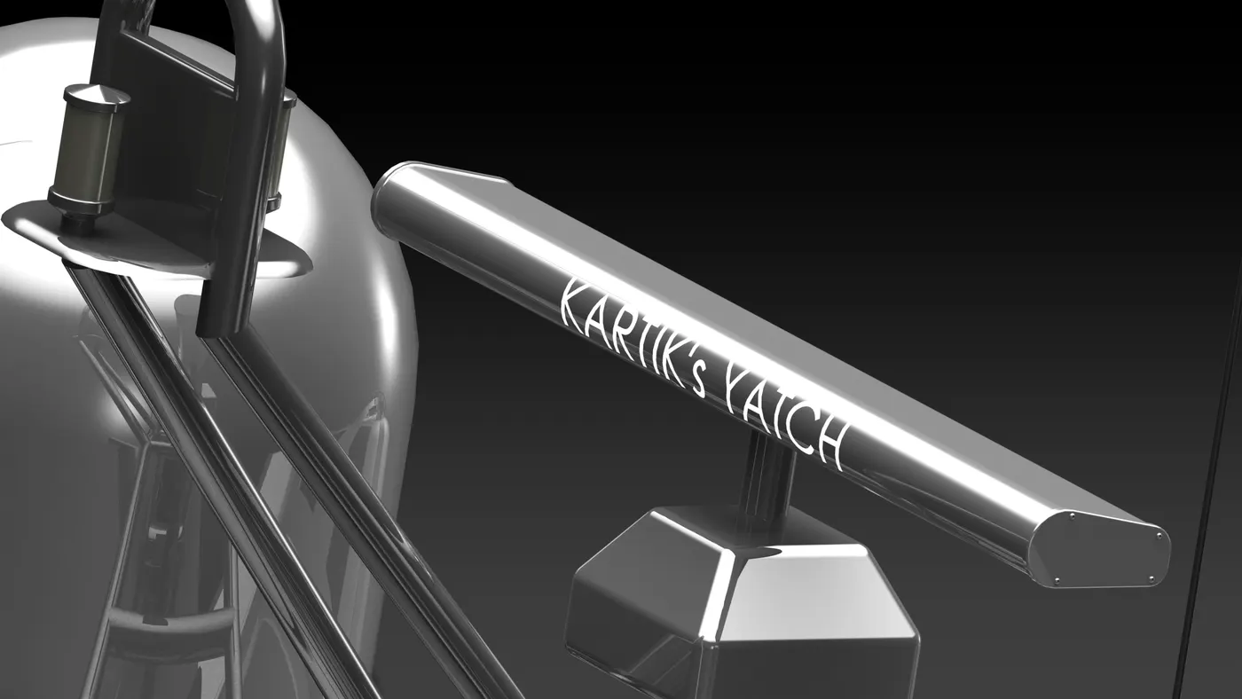
First of all, A sketch is created followed a Boss extrude and some fillets, after that a sketch 2 is created followed by a boss extrude and sketch 3 with boss extrude too and fillet. These are Extrudes which are used to create the bolts. And at last desired text is imprinted on the wall of the RADAR using split line feature.
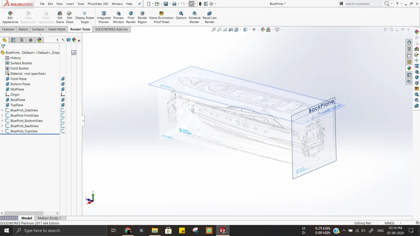
- Blue Prints –
Blue prints are set as shown in the image below-
- Hull –
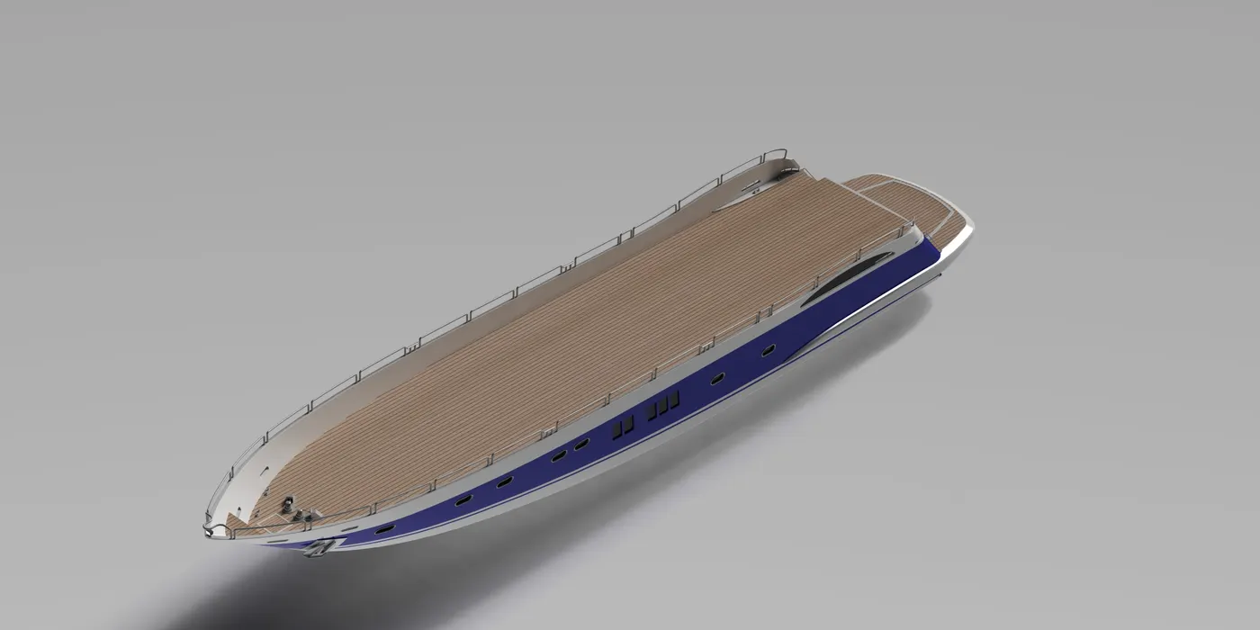
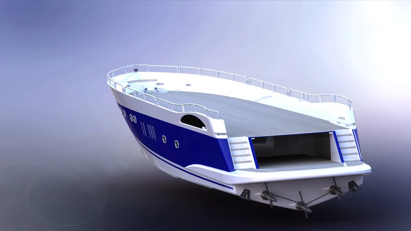
Hull is one the most complicated part of the Yacht as it has many projected curve and minor details that also needed to be taken care of as the whole Yacht is going to be made with the help of the offset zero deck surface in order to align the superstructure and every other part to the HULL.
Hull is made by using commands and features as shown below in the feature tree screenshots.
- Garage Door –
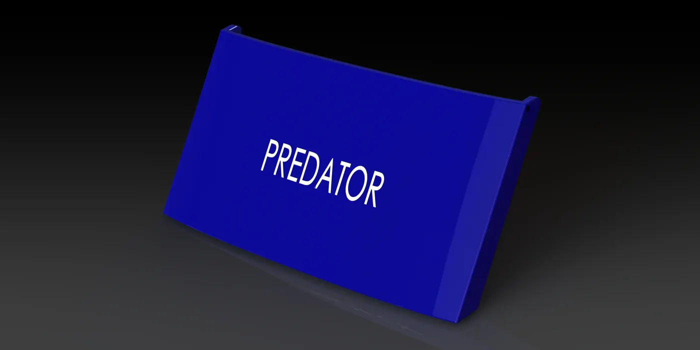
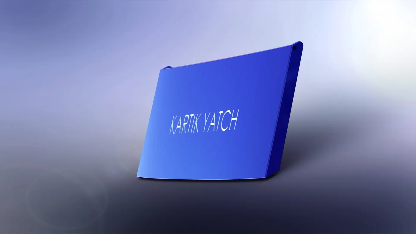
Garage door is made with the help of hull itself during cut extrude process in the hull creation we have used body keeping feature and then used that saved or extracted body part to create the garage door.
Shell features are used and mirror commands are also used in this Part designing.
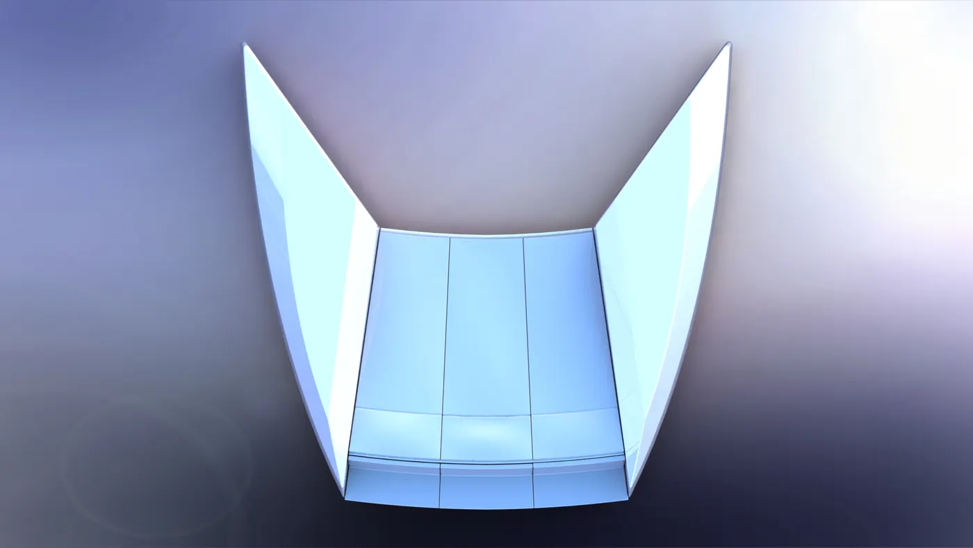
- Front Seat – Two sketches are drawn on the plane 1 and surface sweep is performed then for surface extrude sketch 3 is drawn then surface is trimmed and different types of commands are used in order to create a solid body by performing Knit and other features as shown in the feature tree link below.
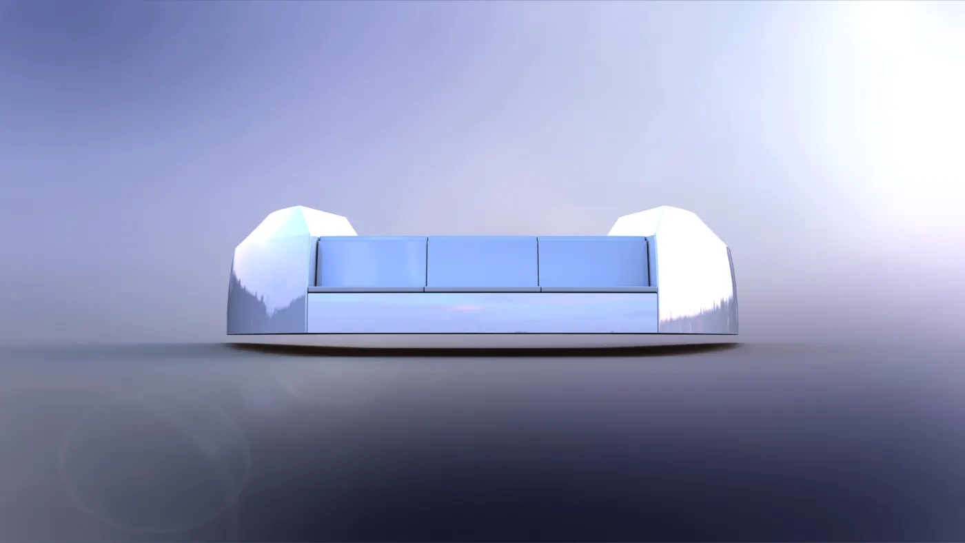
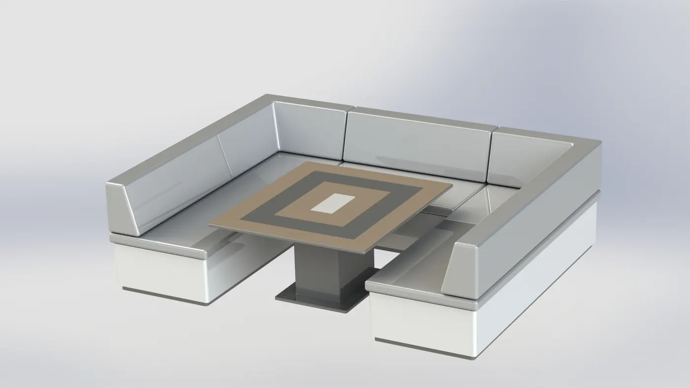
- Middle Seat – Middle seat is made by using solid features like boss extrude, cut extrudes and fillets are used in order to get a finished model. And features used are shown in the feature tree link below.
- Rear Seat – the rear seat designing process is a complicated one as it contains 3d sketches and many surface modelling and the process is shown in the feature tree link below.
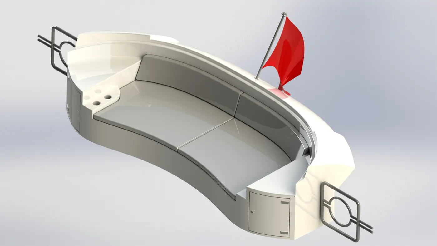
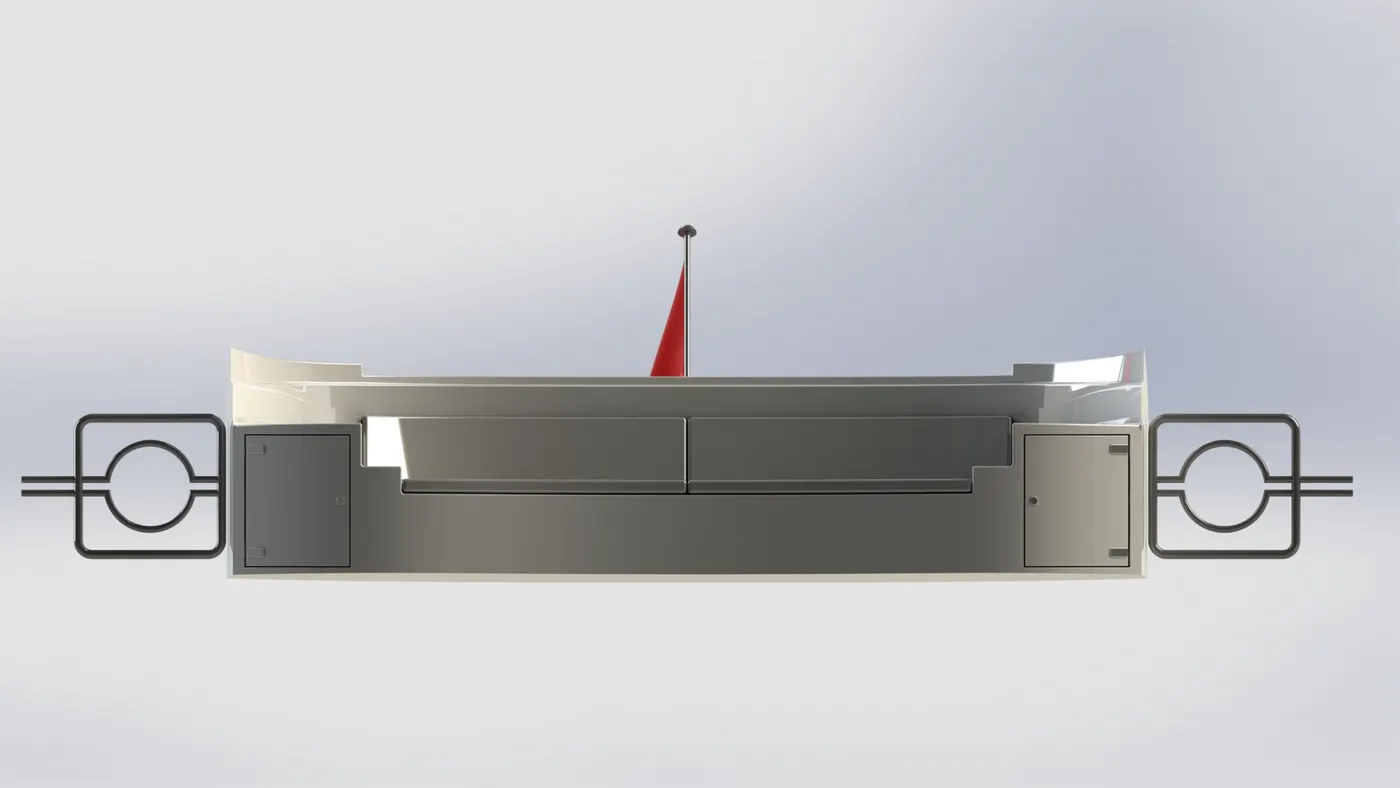
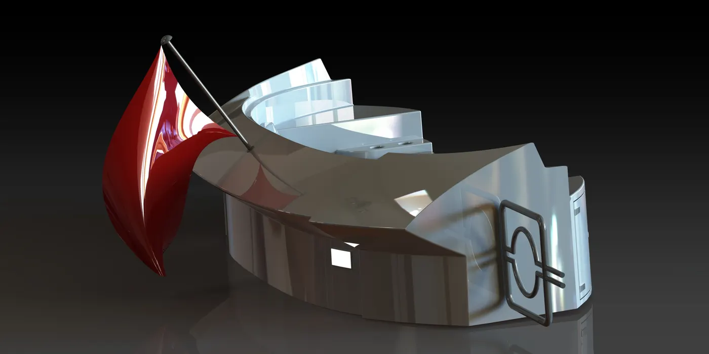
- Superstructure – The design/ Modelling of the Superstructure is quite complicated and it includes many 3D sketches and in the whole, we have learned in depth about the surfacing and because surfacing allows and opens a whole new easiness and help you to create 3D geometries and which will come a lot handy in the solid works modelling career. In the making of superstructure we need to work with surface fill and many or we can say almost every feature we have used is surfacing. And the process of making superstructure is shown below in the feature tree link.
- Radar Mast – The design process of the radar mast is shown in the feature Tree link below.
- Assembly – As all the parts has been designed now its time to assemble them together to form the yacht and after that renders should be done. Steps of assembly process are as follows-
- Step 1 – creating an assembly file in solidworks and inserting the HULL in the workspace and hitting OK to proceed further.
- Step 2 – Now superstructure is inserted in the assembly and mating is done between superstructure bottom surface and deck surface of the Hull i.e. coincident relation.
- Step 3 – radar Mast is inserted and matting between the top surface of the Superstructure and radar mast’s bottom surface is done and the position of the mast on the superstructure is defined by a relation of coincident.
- Step 4 – Now Front seat part is inserted in the assembly and the bottom surface of seat and deck surface are matted with a coincident relation.
- Step 5 – Now Middle Seat is insert and similar process of matting is used as of the Front seat.
- Step 6 – Now the final Rear seat is inserted using insert part feature and similar coincident relation is used between bottom surface and deck surface.
- Step 7 – The garage door is now inserted and coincident relation is used and concentric also used between garage hinge holes and superstructure studs given at the garage entry.
- Step 8 – Three copies of the propeller is used to complete the assembly of the YACHT.
- Step 9 – Radar is installed in the top of the Yacht and mating between Radar mast and the radar is done with a coincident relation.
NOTE – WE CAN USE ANY TYPE OF RELATION FOR EXAMPLE- ALLIGNING PLANES AND GIVING THEM COINCIDENT OR PERPENDICULAR OR COLINEAR REALATION, BASICALLY ITS UPTO THE DESIGNER AND HIS/HER’s EASINESS.
LINK TO THE FEATURE TREES OF EVERY PARTS - https://drive.google.com/drive/folders/1esdthwfE1k9VYvUXGSdnNx9ohZuPd_6I?usp=sharing
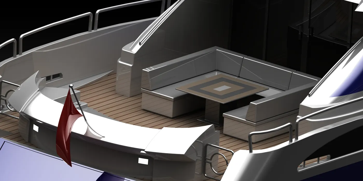
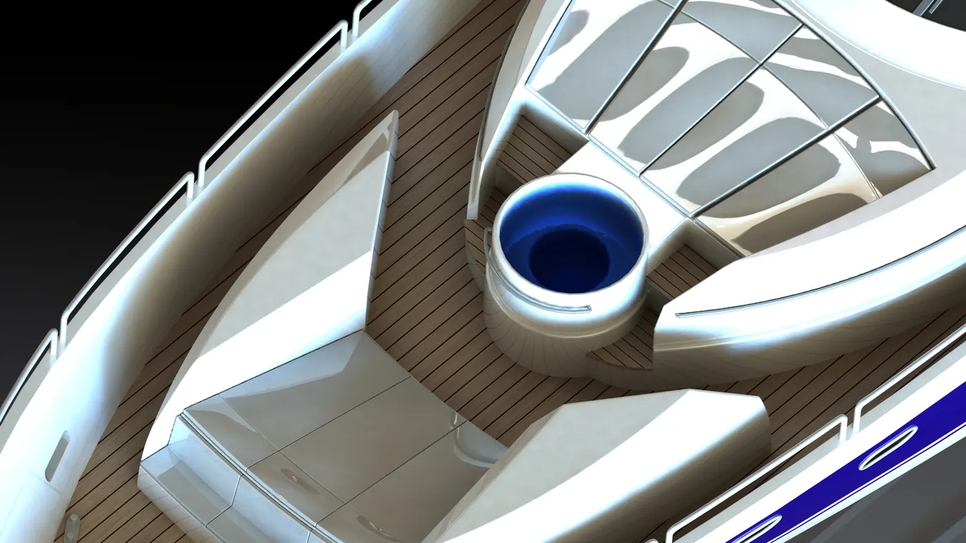
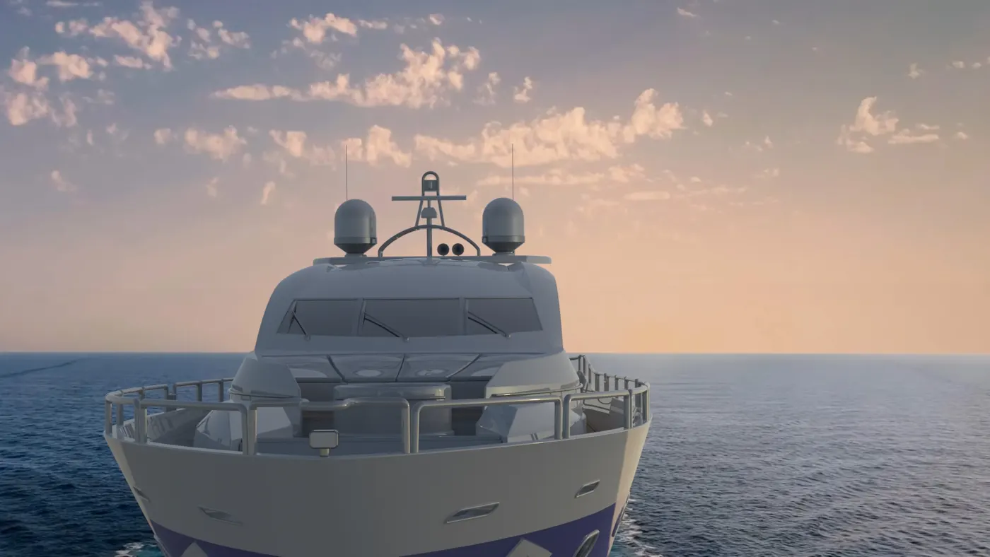
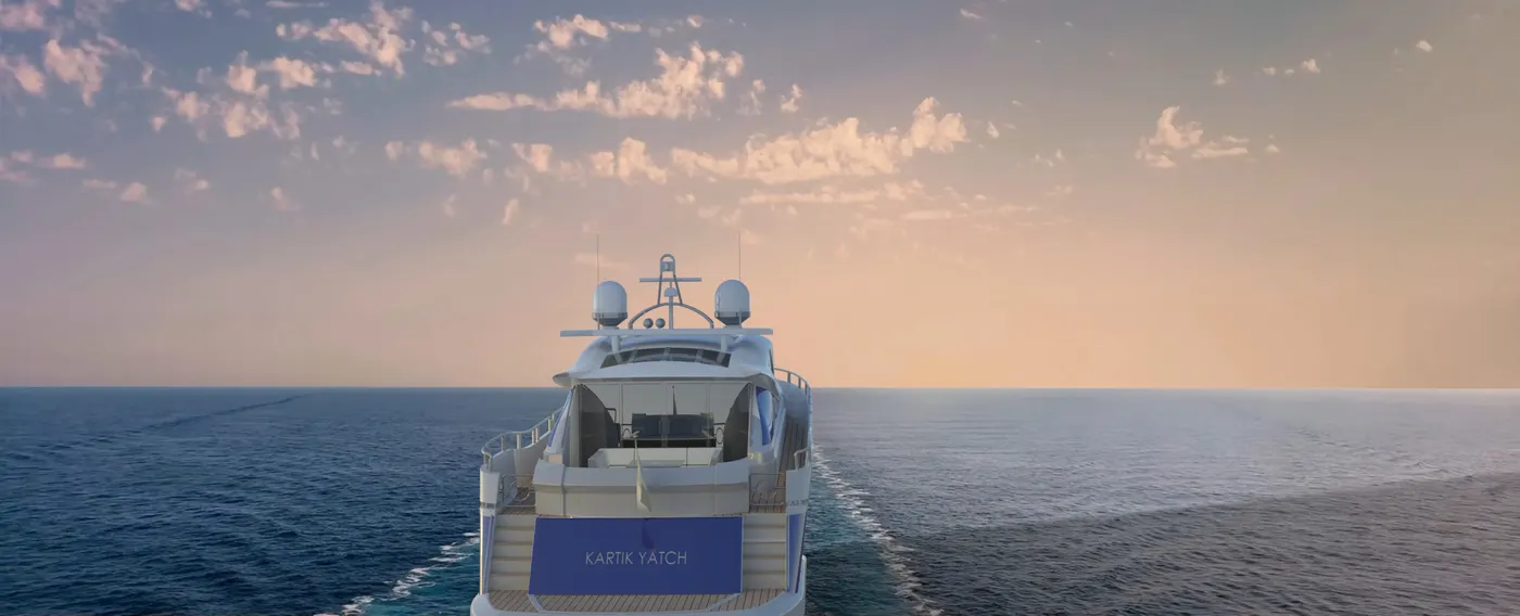
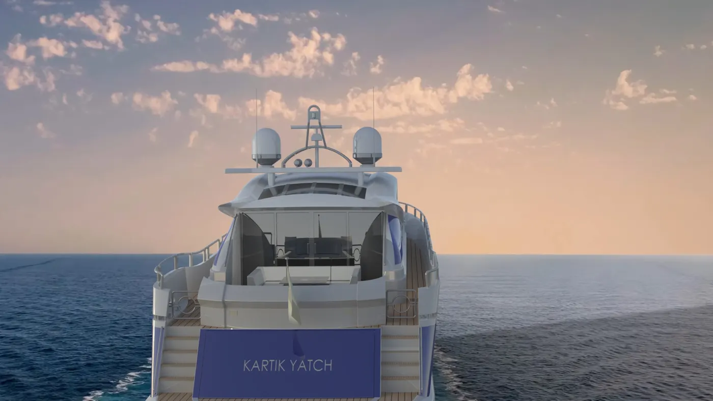
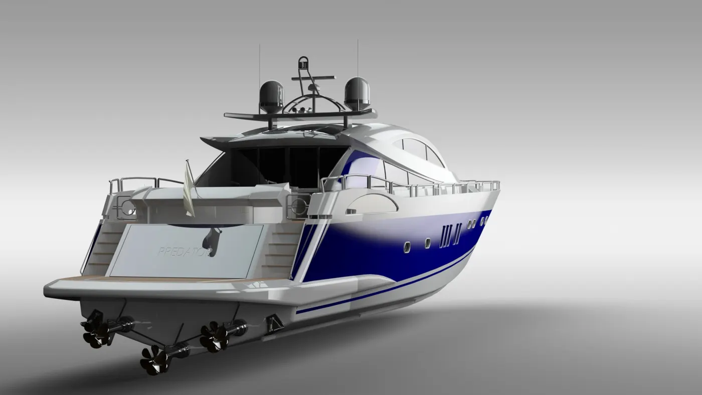
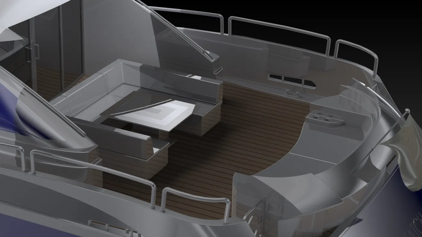
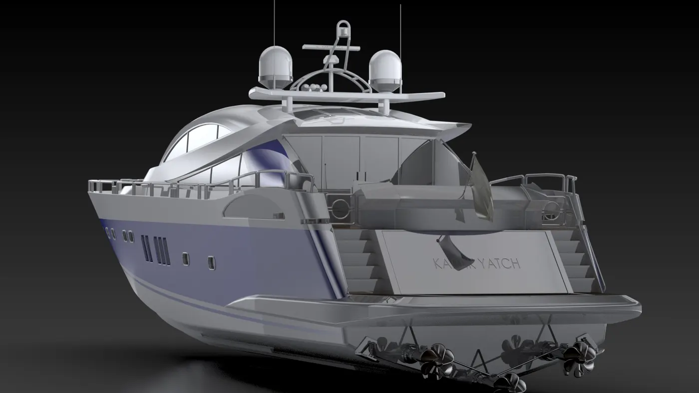
12. RENDERS – I have rendered the YACHT in following Three Software
- PHOTOVIEW 360.
- SOLIDWORKS VISUALIZE.
- KEYSHOT.
IMAGES –