Advanced Sheet Metal Design Using NX Cad Challenge_1_Casing Design
Advance Sheet Metal Modelling of Casing
Objective – To Model the sheet metal Casing using Sheet metal modelling tools in NX Cad.
Introduction –
NX cad is a versatile software as it is used for solid as well as sheet metal modelling. Sheet Metal modelling is the widely used feature of NX Cad.
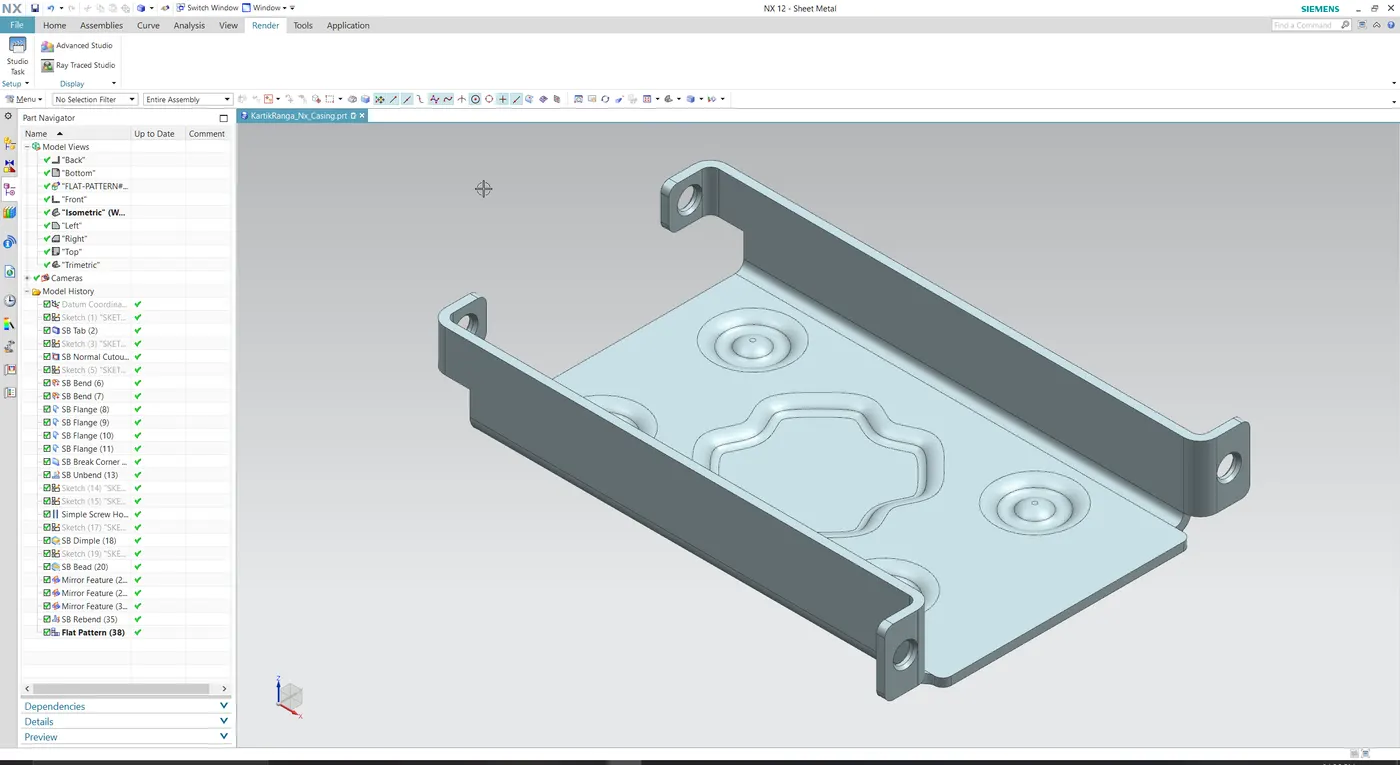
In the project I have modelled a sheet metal Casing and following features are used in order to model it.
- TAB.
- Flanges.
- Normal cut-out.
- Beads.
- Dimple.
- Sketching.
- Dimensioning.
- Make it symmetry.
Design Methodology and procedure –
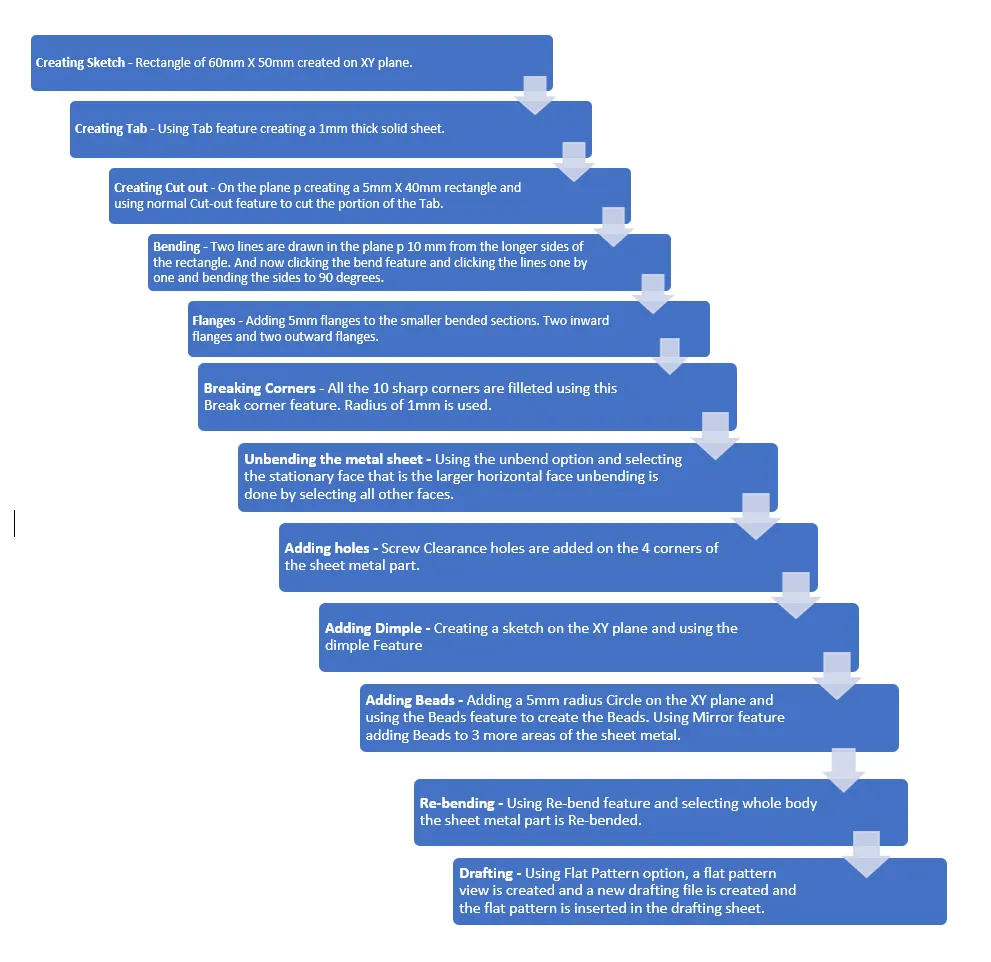
Description and Features Used –
Sketching- The sketching is the basic command used for creating a basic sketch profile which is used for further processing. In this project sketching is used for creating rectangles, holes and straight lines.
Sheet Metal Preferences – sheet metal preference is used for setting up the material thickness, relief depth, Bend radius and relief width etc. For this particular project all the above-mentioned global parameters are set to 1mm.
Tab – creating a solid sheet out of 2D sketch is the basic function of the Tab feature.
Normal Cut-Out – this feature is used to create a cut out in the sheet metal which is always normal to the sheet metal.
Bending - Bending is the feature used for bending a sheet metal with help of a sketch like a straight line.
Flanges – This feature adds a sheet metal part to a specified edge at any desirable angle and length.
Break Corner – this command is used to create a filleted corner.
Unbend – This feature is used to unbend the bended sheet metal part to perform some other features on the sheet metal part.
Holes – used to add Holes in the sheet metal part.
Dimple – This is used to create a dip inside a sheet metal part.
Beads – used to add beads in the sheet metal part.
Mirror – Mirror Feature is used to mirror a body or a feature.
Re-bend – Used to Re-bend the unbended sheet metal part.
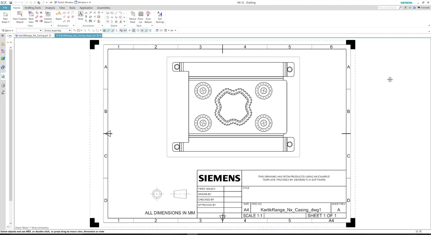
Drafting – This is used to create a draft file of the part which is created in the sheet metal.
Flat Pattern – It is used to create a flat image or view of a 3D part.
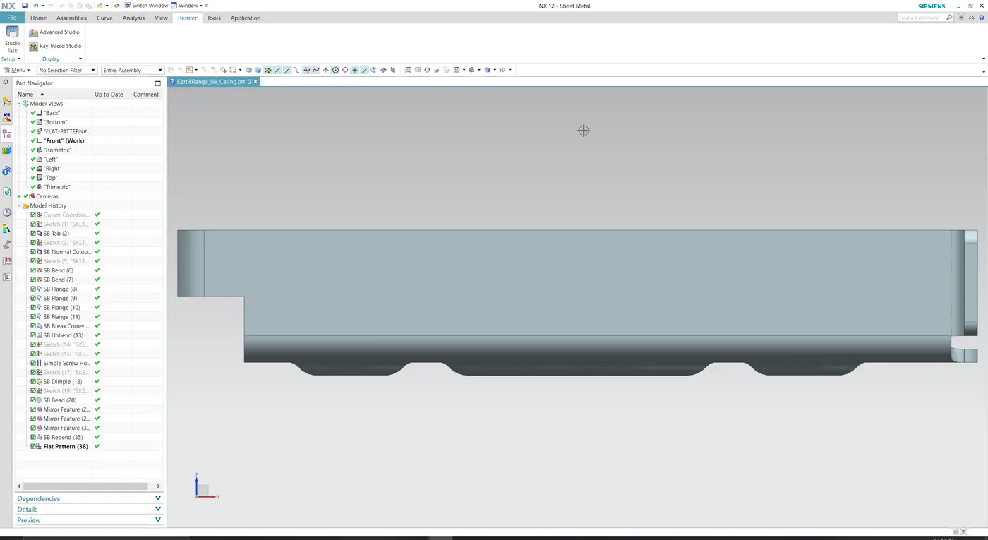
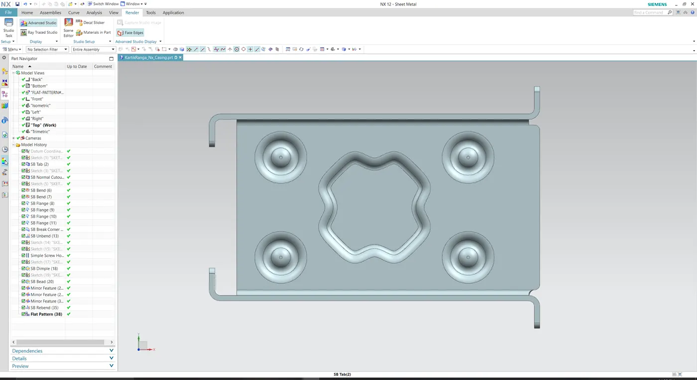
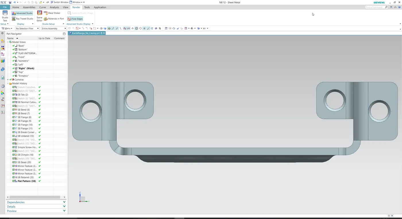
Images of the Advanced sheet Metal Casing.
Drafting Image
Google Drive Link -
Part - https://drive.google.com/file/d/1gM4zgqMzCzadzy94m18M3GREPi5GDthx/view?usp=sharing
Draft Image - https://drive.google.com/file/d/1oxB14O0h38fzsl0UzNIsMpvGX9hRuZvW/view?usp=sharing
Conclusion - Successfully made the sheet metal casing in Siemens NX CAD.