ANSA - Volumetric Meshing for External Aerodynamics
AIM :
Perform the Volumetric meshing of the Car Model used for Geometric Cleanup
Create 6 layers of Prism layer, velocity can be taken as 40 m/s and the y+ as 50
Make a Detailed Report of the Process
Theory :
In order to capture or resolve the strong transverse gradients of the solution (like velocity and temperature etc) within the boundary layer, generally prefer the inflated prism layers in your unstructured tetra mesh. They can allow for suitably flow-aligned high aspect ratio cells (without any excessive stream-wise resolution), thus trying to capture the boundary layer with less numerical diffusion.
however, capture the boundary layer flow details with tetra mesh also but you need highly refined tet cells in the boundary layer region which can substantially increase your mesh count thereby increasing computational effort and hence not preferred.
Since we can capture the boundary layer with a relatively smaller number of cells, prism mesh is preferred for inflation layers at the boundary.
Boundary Layer Mesh
Boundary layer meshing, central for CFD simulations, creates highly anisotropic meshes close to walls without having to use swept meshes or specially designated domains. These elements are needed because of the boundary layers that typically form at no-slip walls, as described in this previous blog post.
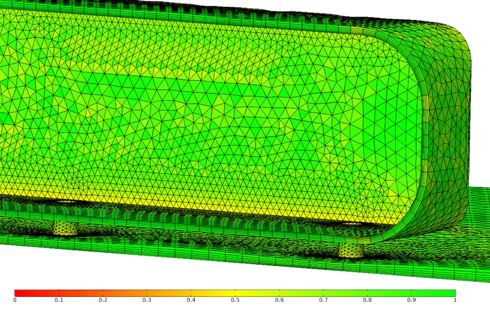
Boundary layer mesh for the Ahmed body model. The elements are colored by quality based on skewness.
In COMSOL Multiphysics, boundary layer meshes are added after the domain has been meshed. Anisotropic prismatic or hexahedral elements are pushed into the computational domain, resulting in a number of highly anisotropic elements as exemplified below. Observe that the quality of the elements is good despite the anisotropy. The reason is that the boundary layer mesh is in this case built from triangles with high quality, and that results in high-quality prismatic elements as well.
Boundary Layer Mesh Characteristics
The boundary layer mesh has three characteristics:
- Height of the first layer
- Growth rate
- Number of layers
The first is the height of the first element and it is often specified as a fraction of the length scale of the face element. A typical default is that the length scale of the face elements is 50 times larger than the height of the first boundary layer element. Higher aspect ratios have the potential to yield a better resolution, but the resulting equation system can also be more difficult to solve, especially when using iterative solvers.
The second characteristic is the stretching factor; that is, the growth rate from one element layer to the next. This is necessary to obtain a decent transition to the unstructured mesh (as shown above). The jump in element size as the roof boundary layer transitions into the unstructured mesh is clearly visible. The boundary layer could do with either a higher stretching factor or more layers in the boundary layer mesh (the number of layers is the third characteristic of the boundary layer mesh). But the boundary layer mesh shown above cannot be much thicker, because the mesh in the gap between the car and the floor is already rather squished in order to avoid high skewness in the unstructured mesh. This compression of the boundary layer mesh is done automatically by the underlying algorithm.
Selecting the first element height, growth rate, and a number of elements is a balancing act between necessary resolution, good transition to the unstructured mesh, and quality of the resulting elements.
Special Considerations for Sharp Edges
If you’ve wrapped your own gifts, you know how easily the paper can rip when tightened around sharp edges. Boundary layer meshes have similar problems, as shown below. The boundary layer mesh elements at the trailing sharp edge are rather skewed, as are the elements just downstream of the airfoil.
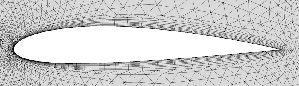
The sharp trailing edge of an airfoil with no special mesh treatment.
One option is to “split” the boundary layer at sharp edges. The result is shown in the middle image below. The boundary layer mesh now ends with two special columns of elements, both starting with a triangle followed by an appropriate number of quadrilateral elements. Splitting allows you to control how sharp a corner must be to be considered sharp, as well as the maximum angle that each “special” column of elements should cover. Optimizing these parameters can greatly improve the element quality at sharp edges.
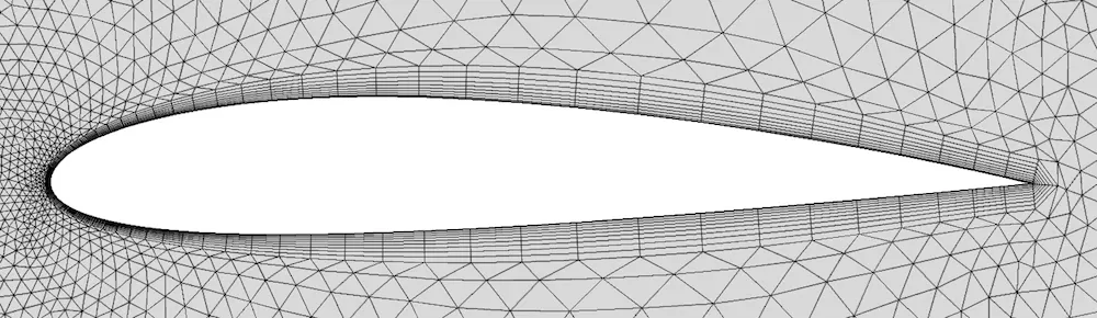
Splitting the boundary layer at the sharp edges of an airfoil.
Splitting doesn’t always work. Complicated 3D CAD geometries, where any number of edges can connect to a sharp corner, are particularly difficult. The algorithm must be programmed for each topologically unique configuration, and it is likely that an advanced geometry contains at least one sharp corner that the algorithm doesn’t know what to do with.
The third way to treat sharp corners can then be an option. It is called trimming and is the default option for sharp corners in COMSOL Multiphysics. The result for the airfoil is shown below. As the layer approaches the sharp edge, it decreases in height with two elements for each element that comes closer to the edge. Alternatively, the method can be regarded as a growth of the number of boundary layer elements from the sharp edge. The number of elements to grow and the minimum angle for trimming can both be controlled in order to obtain an optimal mesh.
Trimming reduces the effective resolution at the sharp corner, compared to no treatment or splitting. Trimming should therefore always be combined with a general refinement of the mesh, which is why the Corner Refinement feature discussed above is included by default in the physics-induced mesh sequence.
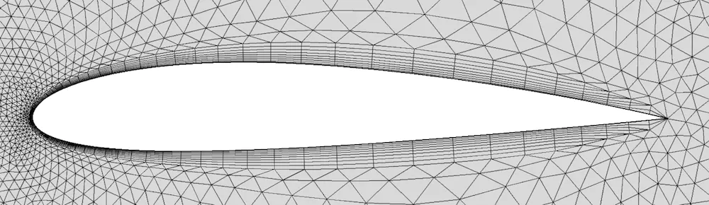
Trimming, the default option for meshing a boundary layer with sharp corners.
Boundary layer meshes can increase the resolution in narrow regions. If you look closely at the mesh in the region between the car and the floor is covered by 15 elements (6 + 3 + 6). This is enough to represent any velocity profile that can occur in that narrow region. Without the boundary layer mesh, the gap would be covered by only 3 elements, severely limiting the capability of the mesh to represent the flow profile beneath the Ahmed body. Then, the flow is typically artificially throttled so that the narrow region appears even more narrow numerically than it is geometrically. Boundary layer meshes can hence be of use, not only for turbulent boundary layers but also in laminar and even microfluidic systems. A good rule of thumb: Narrow regions must be resolved with at least five elements across.
In volumetric meshing, there is a thickness for the surface mesh.
Since we have performed surface meshing already we are using that geometry and performing the volumetric mesh and the prism layers.
To create prism layers near the boundary is called a boundary layer.
boundary layer is used to capture the physical properties more accurately.
To create a prism layer we need the length of the geometry if we perform external flow analysis. and the diameter if we perform internal flow analysis.
We are a chare steric length of 4.5m and the velocity of the fluids is 40m/s and the y+ value is 50 based on this we are going to create a first layer height.
as mentioned above there should be a growth rate for this boundary layer we will have to take care it should not reach the boundary layer thickness.
to Create prism layers :
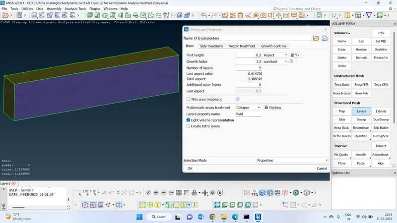
Define first layer height by using boundary values :
We are considering air is the fluid medium.and the density is1.225kg/m^3.we have created a 6 layers of prism only at the exterior surface
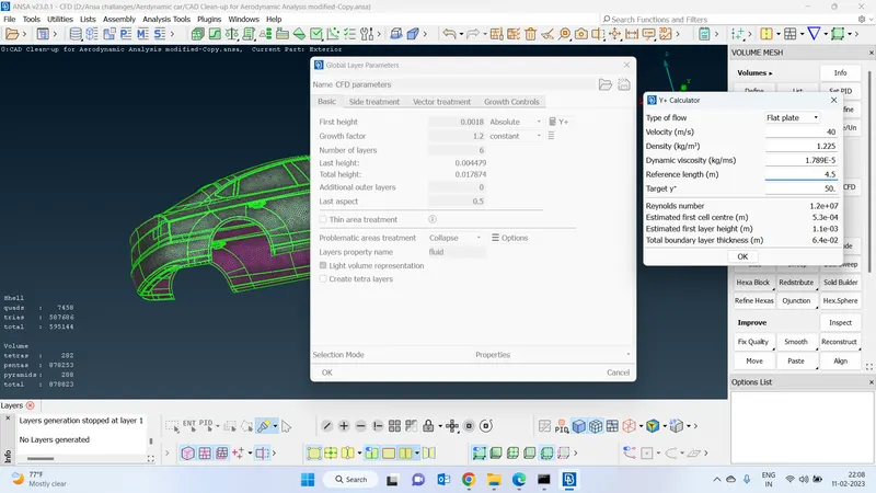
prism layers on the Exterior part :
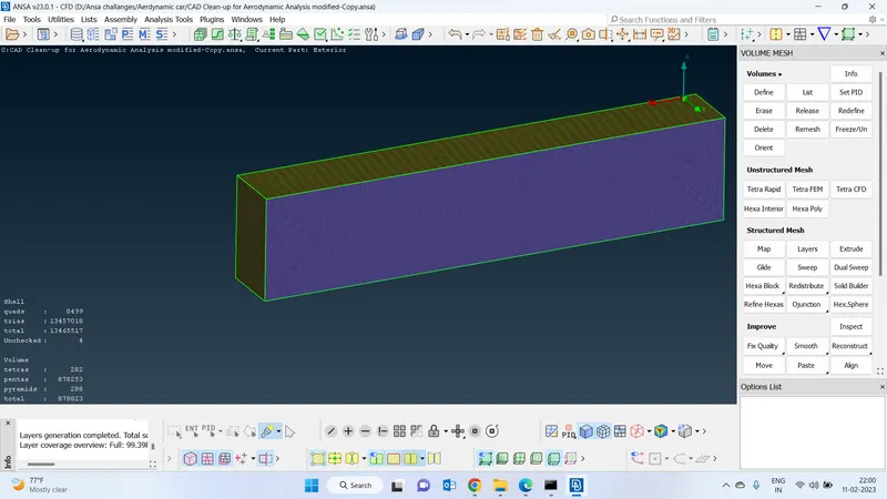
prism layers on the external face :
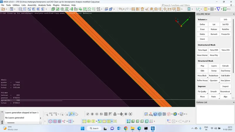
We will have to perform the volumetric meshing after creating prism layers. go to the volumetric mesh and define and select parts where we want to the volumetric mesh and click on the mesh. it will automatically create a volumetric mesh based on the surface mesh
I am not able to perform the volumetric mesh since the system doesn't meet the requirements