ANSA_PROJECT 1 - COMPLETE 2D & TETRA MESHING OF CAR SEAT MODEL ALONG WITH ALL CONNECTIONS
AIM
To generate mesh and deploy connections in the seat model after performing geometry cleanup and generating midsurface using ANSA.
INTRODUCTION
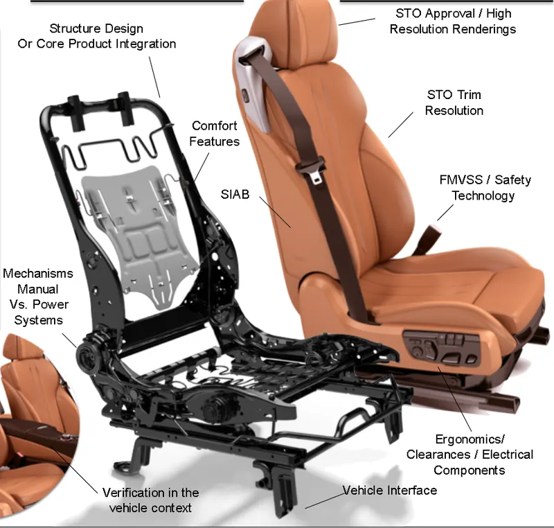
Automotive seat is used to give comfort to the person who is driving. The cushioning agent is especially important when considering that moving cars can transmit vibrations near the human spine's resonant frequency of 3 Hz. The base can usually be moved forward and back on metal railings and may move up and down to adjust to different body types. This movement is accomplished either by manual latches or by electric levers.
Seat system is the very important part of the vehicle which always comes in contact with the occupant when the vehicle is used and is also directly responsible for the comfort/safety of the occupant. The main fuctions of seat are
PROCEDURE
- Geometry Cleanup of an Automotive seat structure
- Mid surfacing and meshing by using various techniques
- Solving failed elements to get quality mesh
- Deploying various connections for NVH Analysis
STEPS
- Import the model using file_open.
- The given model should be analysed properly.
- The model seems complex as it consists of many ribs.
- To reduce the complexity and for better visualisation of curves and fillets, select 'length' from Perimeters and change perimeters and macros to 4.
- Apply topo on the selected view and check up the geometry.
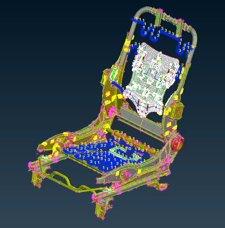
- As it is symmetric model, half of the model is only taken for preprocessing.
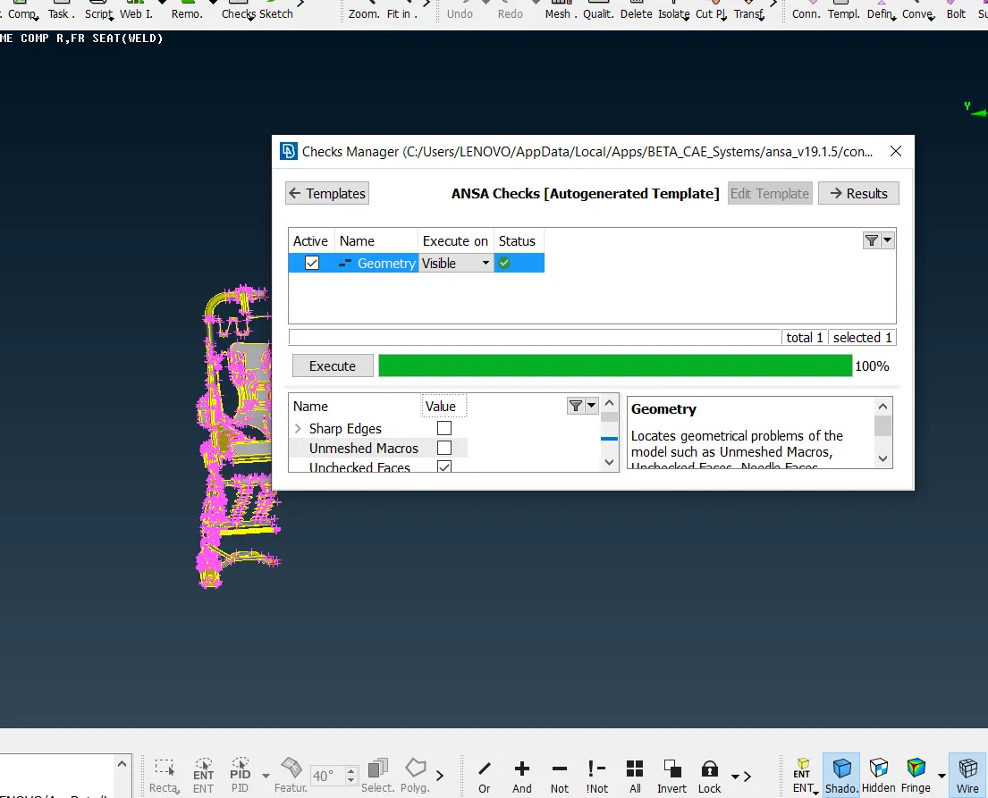
- The large number of geometric error are present on checking geometry.
- Unchecked faces, triple cons and single cons are the common errors found and it should be eliminated using the topo
2.MIDSURFACING
- Midsurface can be obtained manually and automatically by using Midsurf command.
- Here, midsurface is generated manually by using OFFSET.
- After generating midsurface , check for geometry once again.
- To eliminate triple cons present, release the cons and apply topo to the appropriate cons.
- Hide the parent geometry and obtain the midsurface plane.
- Go to orient and change the model into same colour if it is differing.
- Set PID and it will be saved in properties.
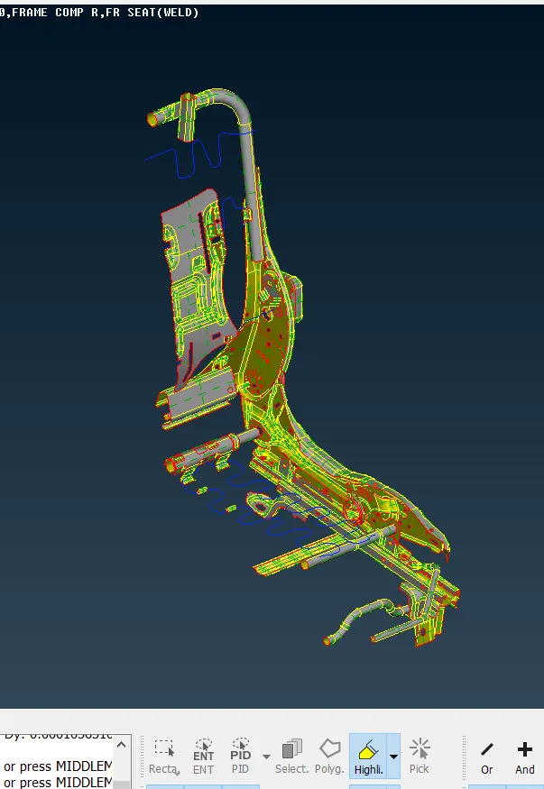
- Midsurface of all necessary components are taken and it is shown below.
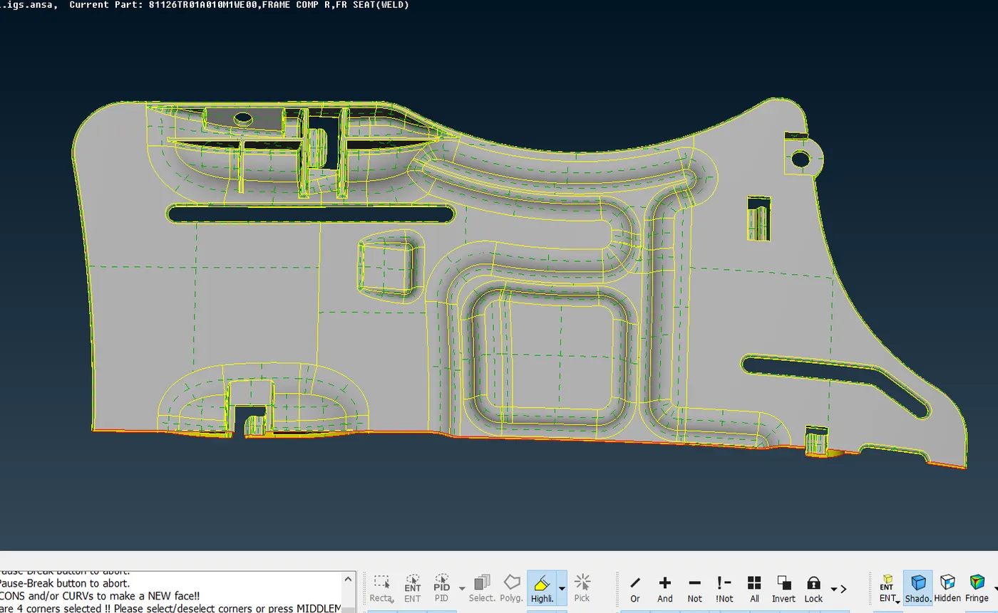
- The back frame of the seat is shown above and the thickness varies throughout this model and the midplane is taken part by part at different thickness.Seat frame midplane
- The below shown part consists of curved features and it should be captured without distortion using curves middle option.
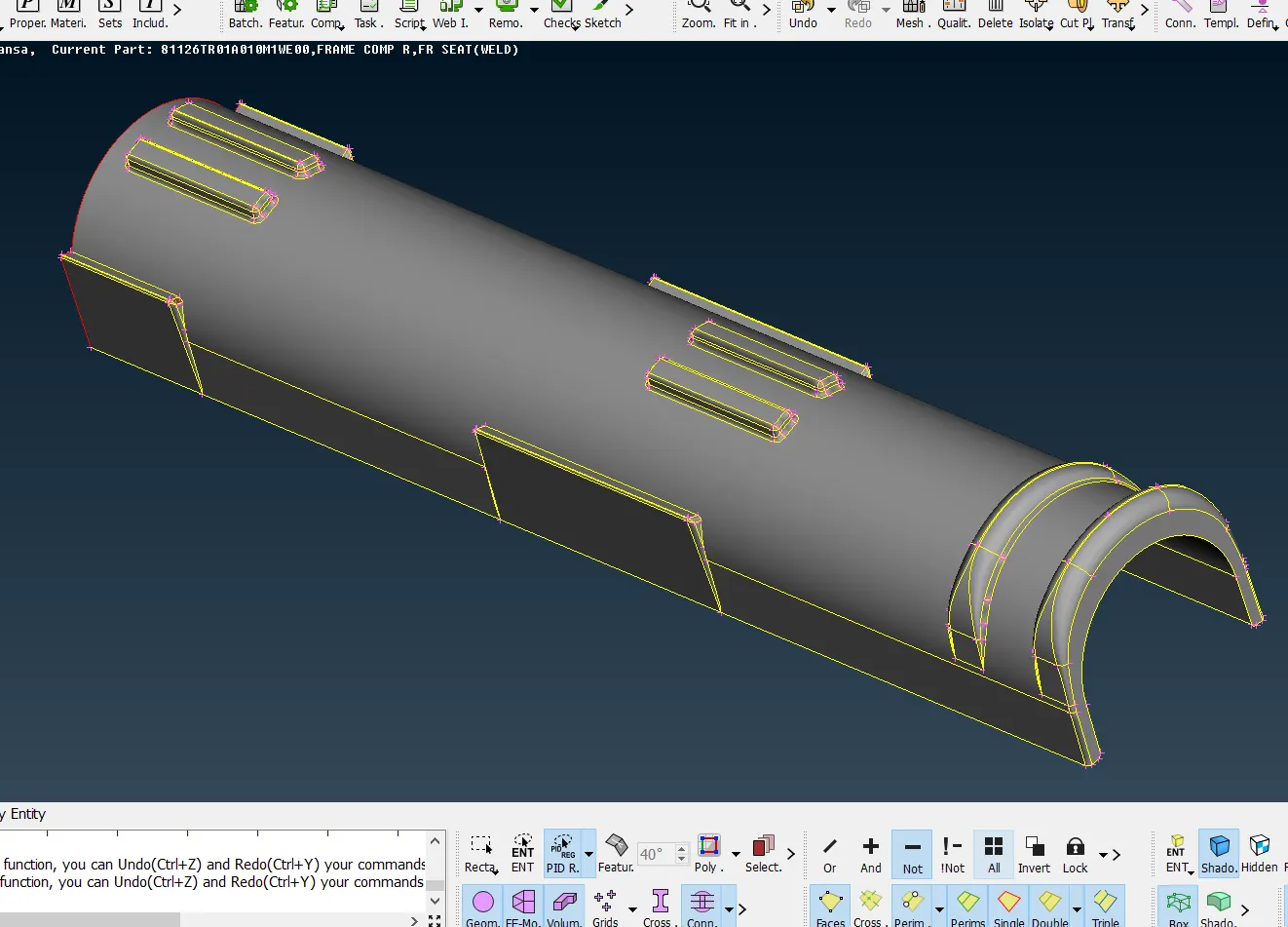
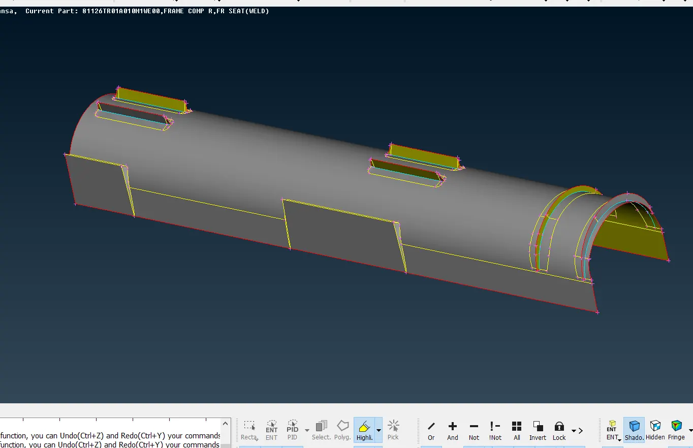
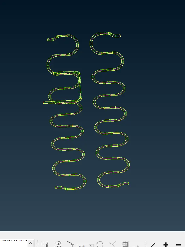
- Here the seat structure consists of torsion springs in base cushion as well as back cushion.
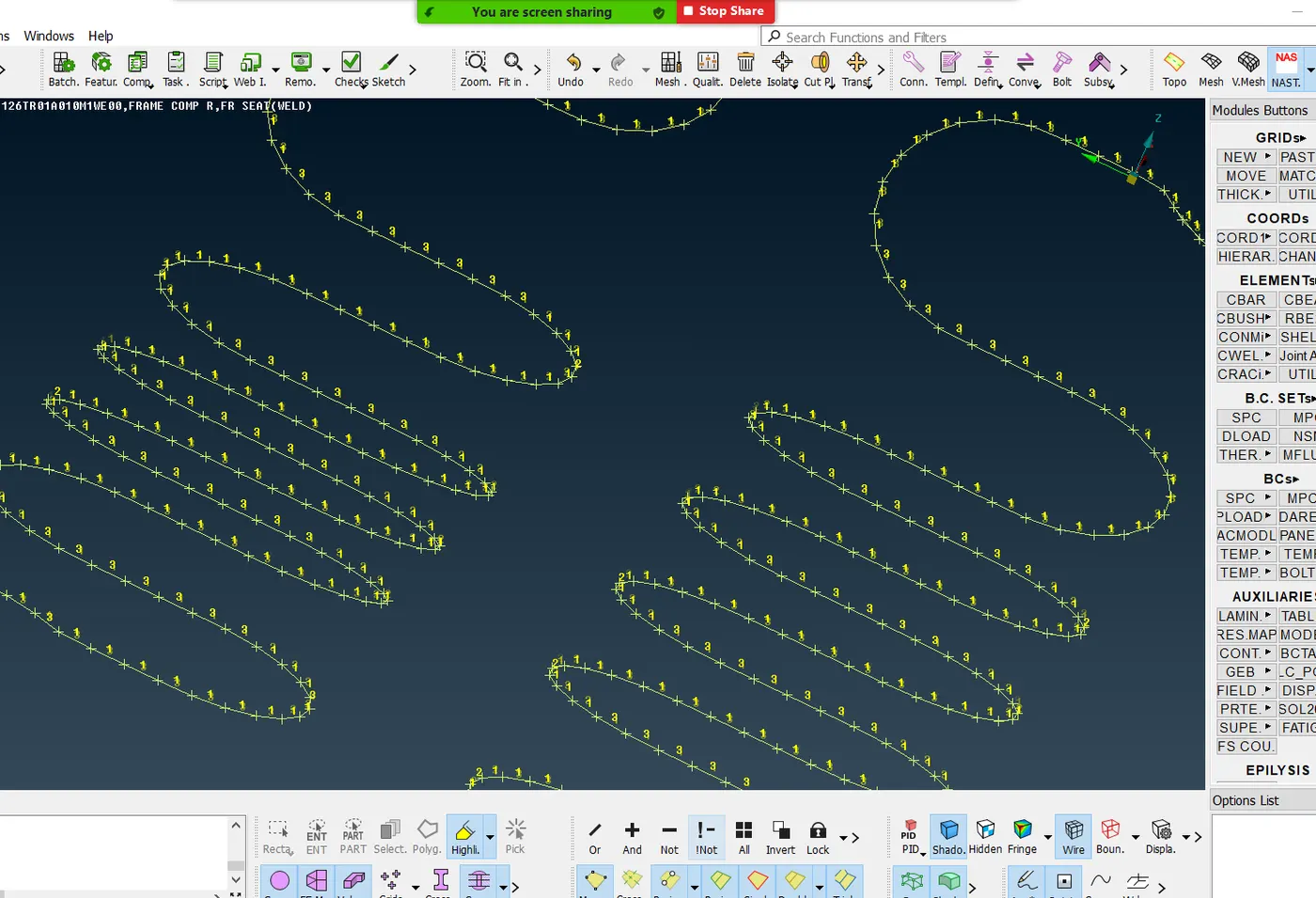
- The torsion springs are represented in 1D element by introducing CBAR under nastran deck.
- Initially the curves middle is taken for the entire spring and the curve generated is recognised on introducing CBAR from ELEMENTs under NASTRAN deck as shown below.
MIDSURFACE GENERATED
MESHING
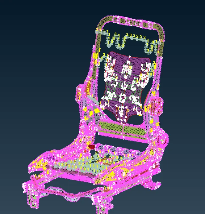
*A mesh is a network that is formed of cells and points. It can have almost any shape in any size and is used to solve Partial differential equation.Each cell of the mesh represents an individual soultion of equation which, when combined for whole network,results in a solution of entire mesh.
*On meshing the model element size must be consistent and so set element length in perimeters. Here as per the given details, it is 1.
*Quality criteria and meshing parameters should be entered according to the given values.
*In quality criteria aspect, skewness, angle, minimum length, maximum length and jacobian is considered here.
*In presentation parameters of Quality criteria, tick the elements % and all details to track trias and off elements.
*If diamond structure or any other feature is available in the model, run the number in perimeters and select the structure.
*By making sure it is even number, slide the structure according to the way of meshing.
*Check all the fillets before meshing to make sure it is under the minimum length given for meshing.
*Mesh the features initially and the construction lines can be altered without effecting the fillets of the features for a better mesh.
MESHED MODEL
SOLID MESHING
Step 6 : Meshing
- Now we have to generate the Tria mesh for our component
- For thet Select the BEST in the MESH GENERATION option
- BEST command gives the better mesh quality by using its best algorithm
- Then change to HIDDEN mode from shadow mode for identifing element fails
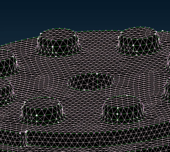
- By using the RECONSTRUCTION and SPLIT commands give the better mesh flow for that surface
- Avoid Quad elements at fillets. Eliminate them by using Swap, Split and Join commands
- No mesh Transition on constant radius fillets/curvatures.
- It is always preferable to have two or more rows of elements at fillets so that the FE model will capture the curvature.In one fillet there should not be variation in number of rows throughout.
- To create two rows of elements, Split by Edges can be usedCircular holes aInstead of zig zag mesh pattern, a structured or smooth mesh is recommended.
- i.e. Nodes should be aligned in the same linere much important in Durability, Fatigue and NVH analysis.
- So it should be modeled carefully with at least one layer of quad elements around the periphery of a circular hole.
- Tria elements will add stiffness so it is not desired to have tria elements .
- These above steps has to be followed for aother componwnts also
Step 7 : Define the Component
- After doing the 2D mesh on surface of the mirror, Now we move to the Volume mesh panel
- Before doing the tetramesh to the mirror, we have to define the Each component, so that ANSA will recogonise and give the tetramesh properly
- For that click the DEFINE command in the VOLUME tab
- After that select the each component and Assign the seperate PSOLID profile
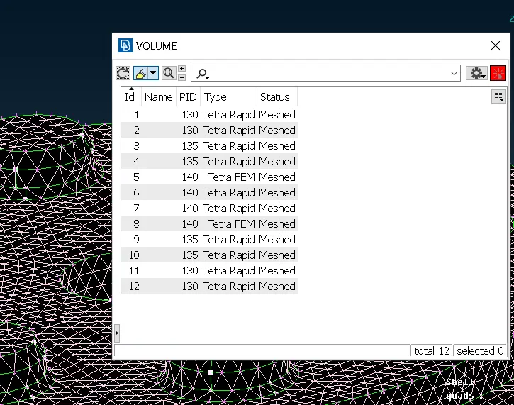
Step 8 : Volume Meshing
- Select the Tetra rapid or Tetra Fem command under the Unstructured mesh
- Now select the Each component and Press ok
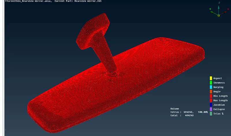
- Then ANSA gives the best possible volume mesh to our component
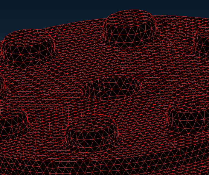
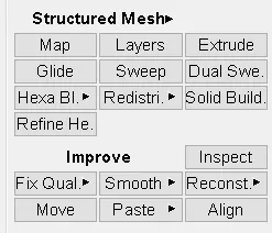
- Now clear the failed elements by using any following commands below
FINAL COMPONENT
CONNECTIONS
* Connections play a major role in preprocessing of structures for analysis. Connection method is of connecting two sub components of a model.
* It provides necessary constraints to a particular region.
1.Welding
* Welding is a major connecting method used in ANSA. The sub components are connected with different sorts of weld and the weld type is determined depending upon the components and the area to be welded.
* Here entities are selected in the region to be welded with the help of Feat2curves in perimeters under mesh deck.
*The curve generated is then converted into seamline with the help of conversion in the topmost bar.
* Conncetion manager is used to introduce the type of weld and to recognise the connecting components
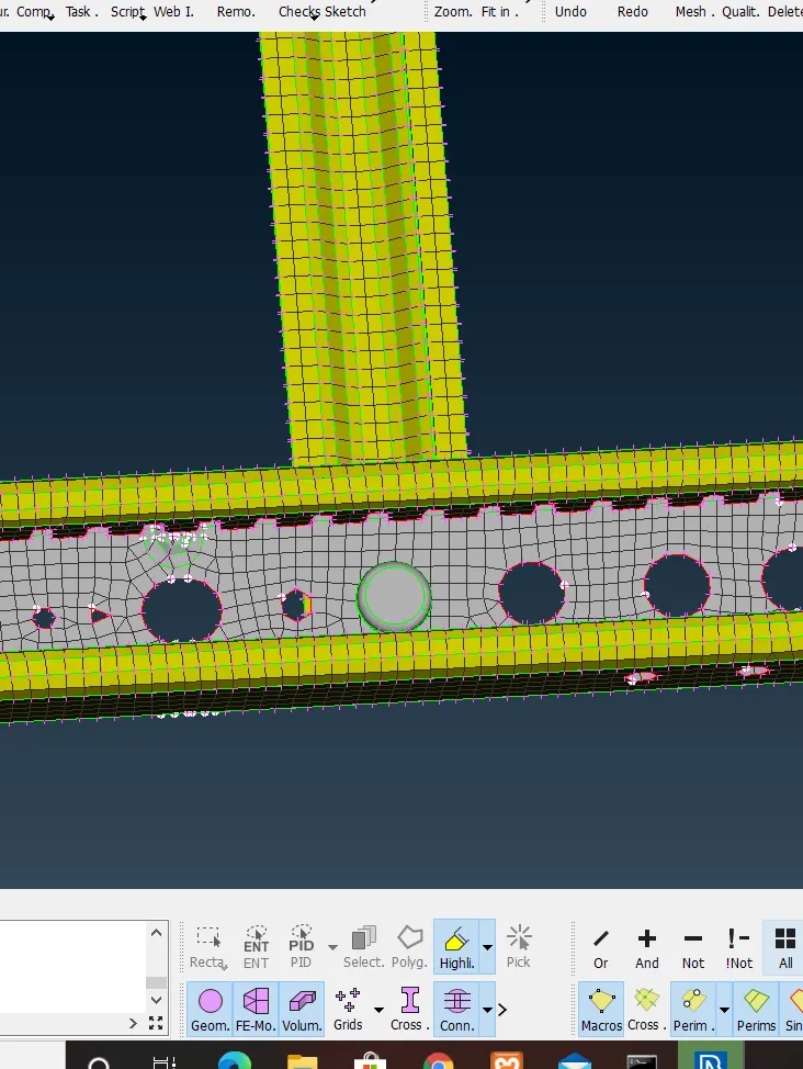
Overlap shell
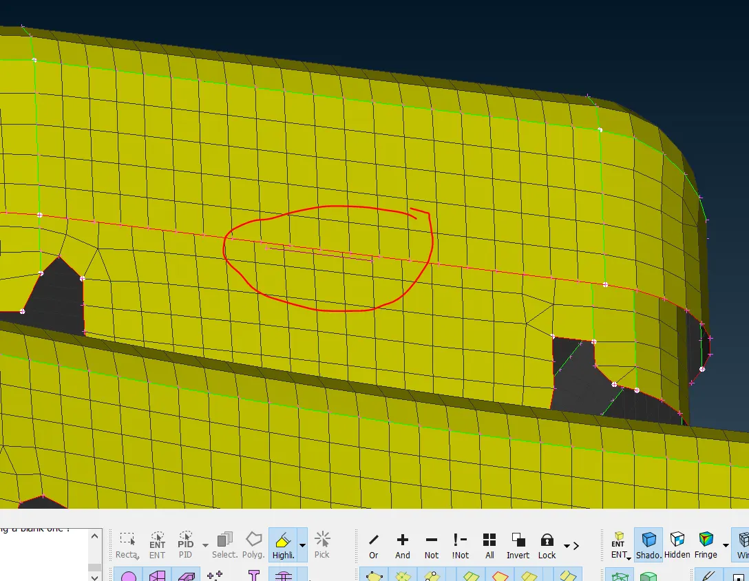
* If the surfaces of two components to be connected are facing parallel to each other, overlap shell type weld is used.
Y-joint shell
*If the surfaces of two components to be connected are perpendicular to each other, Y-joint shell type weld is used.
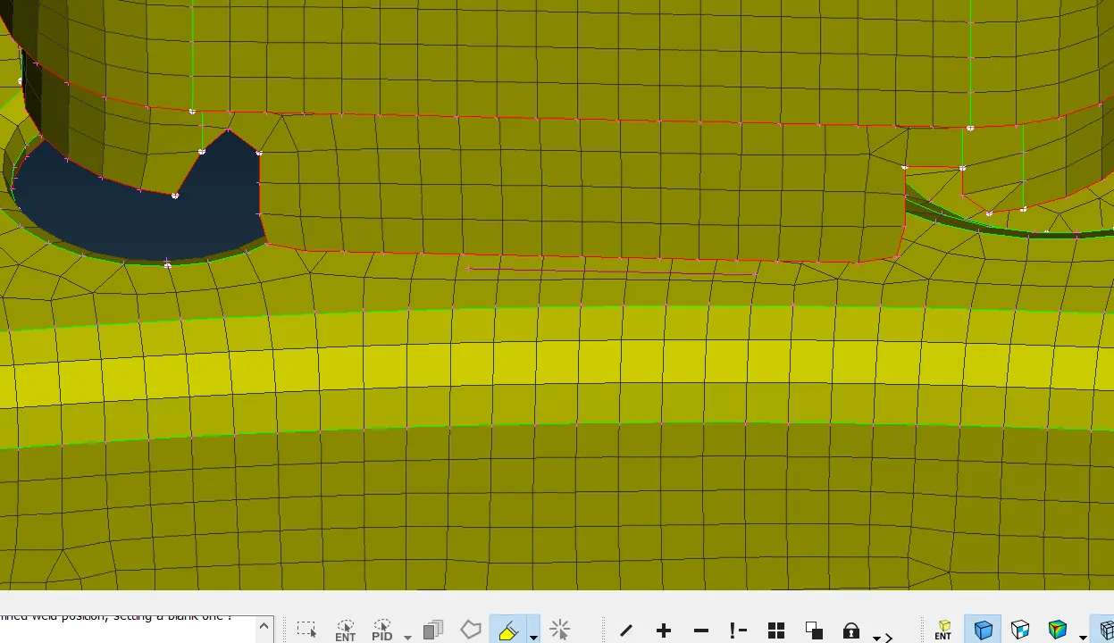
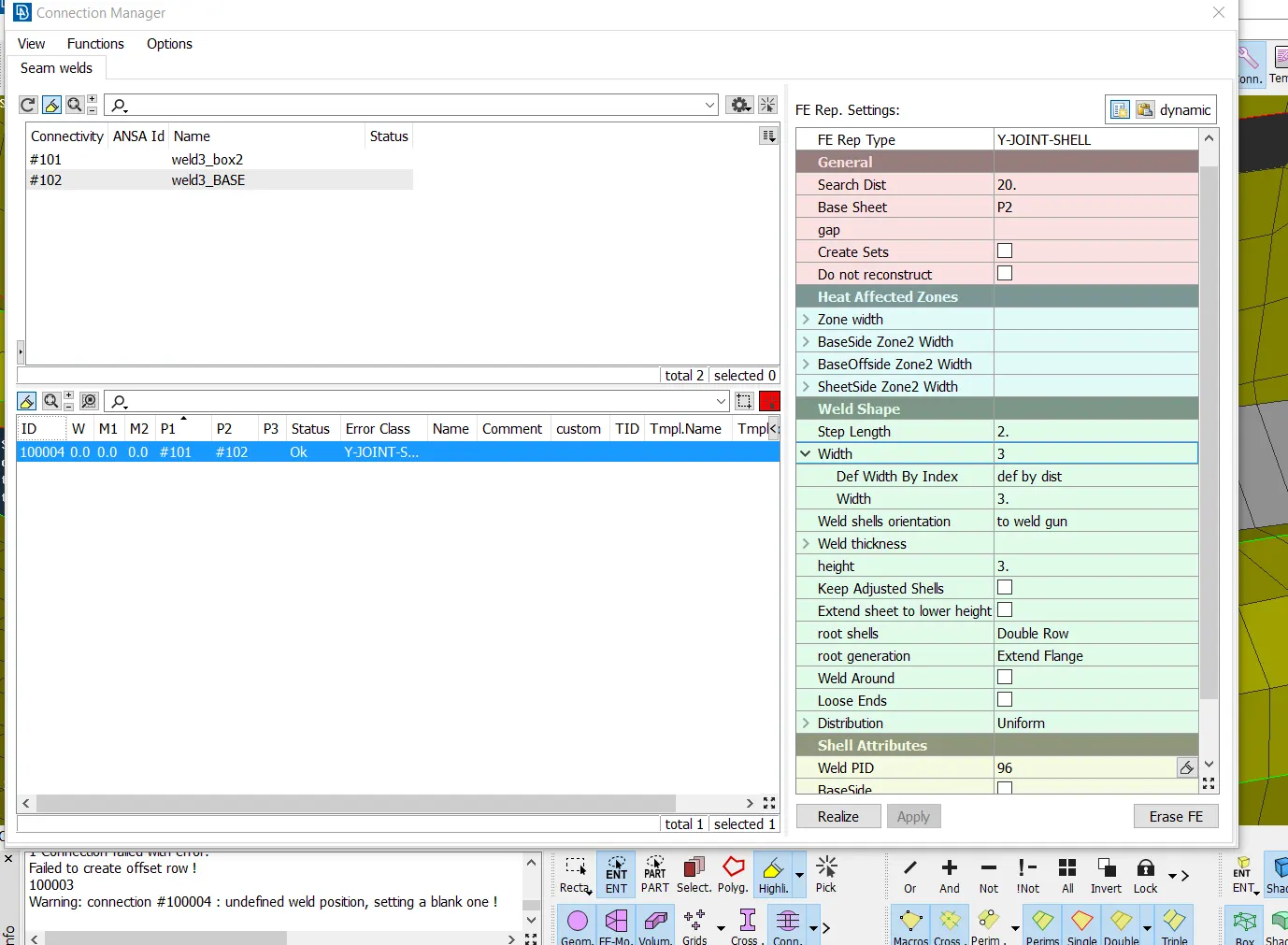
* The below image shows the best example of overlap and y joint weld
2.Bolting
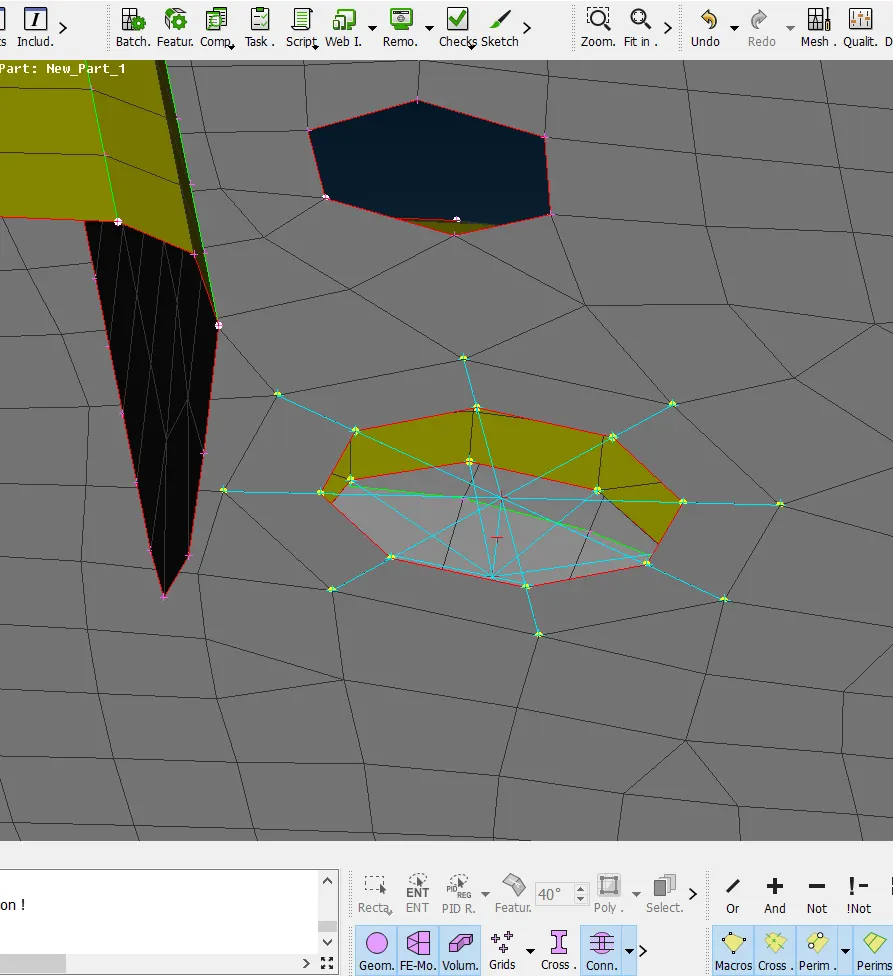
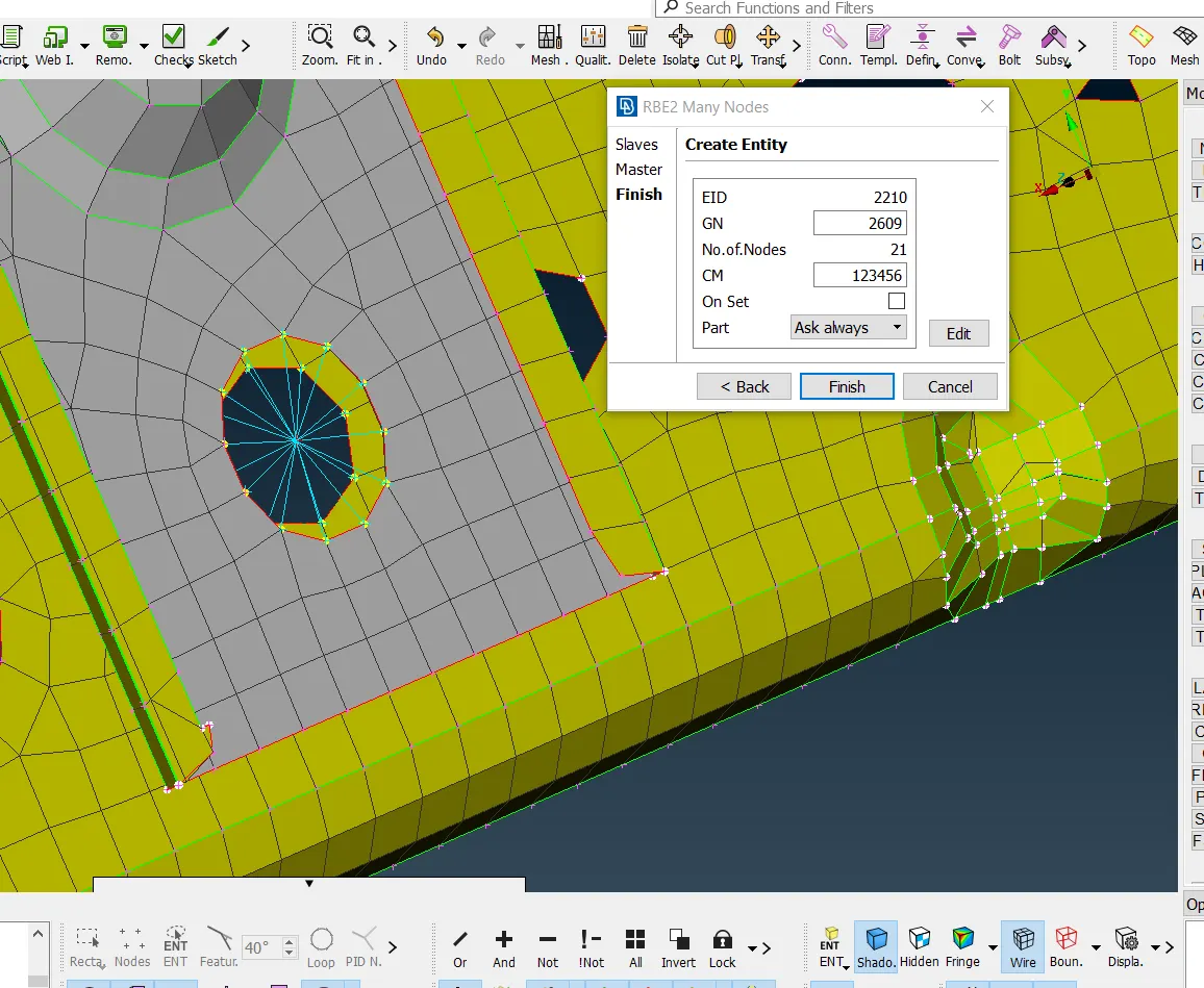
* Bolting region is mainly handled by RBE2 connections. RBE2 connection is that the slave nodes will be forming the spider and the center node will be the master node.
* When nut and bolt is present on a single component RBE2 connections are introduced after providing a zone cut on the surface.
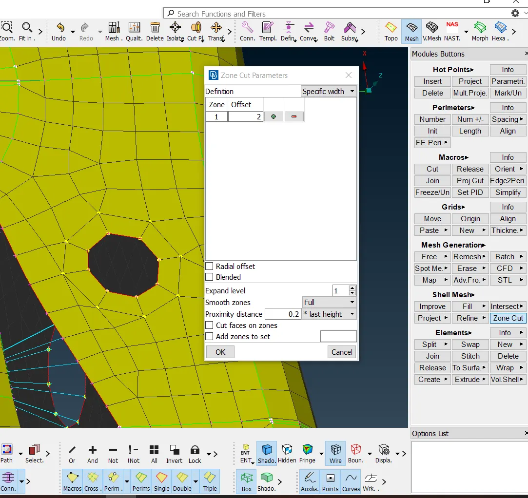
*When nut and bolt connection is done between two components, the nut and bolt areas are introduced with RBE2 connection and then connected with a spindle.
Rivet connection
* Cluster RBE2 connections are followed in rivet regions.
*Cluster RBE2 is the spider formation with one master node for both the surfaces as shown below.
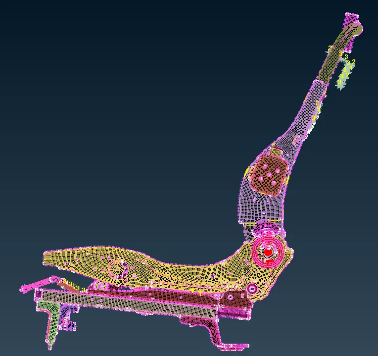
SEAT STRUCTURE WITH CONNECTIONS
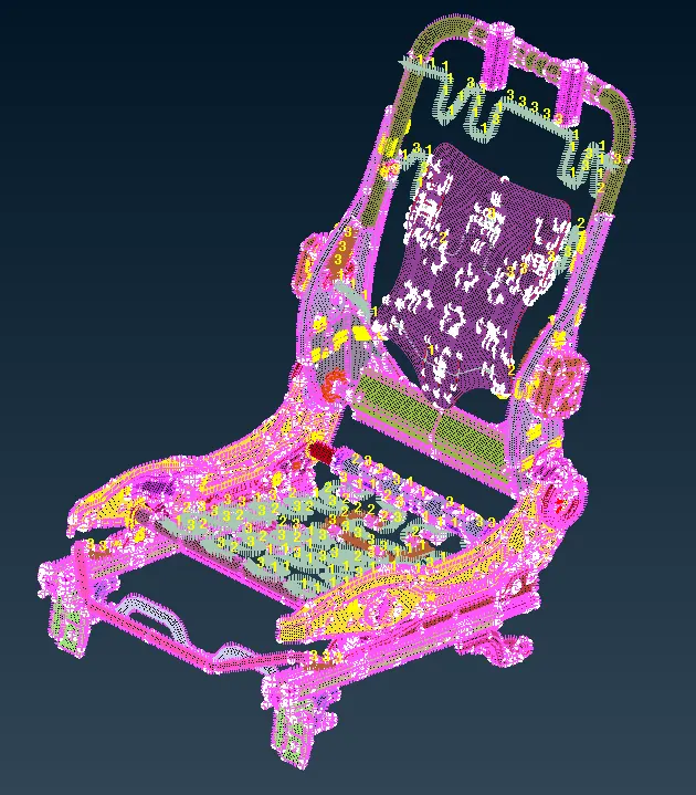
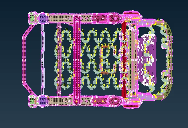
* After deploying all sorts of connection in the appropriate areas TRANSFORM< COPY is given selecting the whole entities and a symmetry is obtained.
CONCLUSION
* In preprocessing meshing and connections are significant as it helps in the flow of stress evenly throughout the model.
* The complexity of the model is taken down by recognising and assigning each component in different PIDs.
*Appropriate bolt connections are given using cluster RBE2 under NASTRAN deck.
*The region to be welded is connected using Overlap shell and YJoint shell type