ANSA - Meshing of Pressure Valve
Perform the Meshing of Pressure Valve . The geometry should be free of error . Perform the meshing using any three different target lengths starting from 5 mm to 0.5 mm
Explain for each part which target length is suitable and why
Make a Detailed report including the step by step procedure and snapshots for meshing of each part
Make a Detailed report regarding the various tools and algorithams used for meshing in ANSA
Disclaimer:
ALL the dimensions are in mm.
The resolution and target length has been considered based on the system specification.
Used only triangular elements to do meshing
Resolution :
Resolution 10 :
-For the demonstration purpose I have varied the resolution from a maximum to a minimum length.
-So that we can clearly see in a better way how the geometry is varying.
-If we increase the resolution it means we will get the property geometries it will help us clean up the geometry in a better way
the below picture refers to the low resolution of the geometry
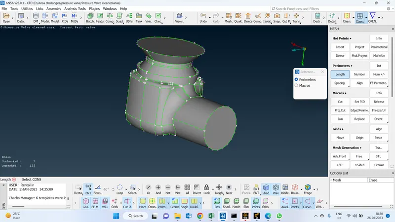
To increase the resolution
go to the mesh deck module > perimeters >select the geometry>provide the length (10) and then the middle click of the mouse will get the above geometry [Followed the same command sfor the next two screenshots]
Resolution 5
-When compared to the previous one the resolution has been incresed to the 5 by giving the length 5
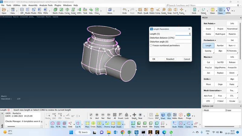
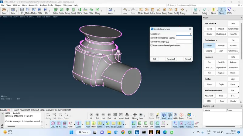
Resolution 2:
-When compared to the previous two this one is the better resolutioned geometry. in this geomtry we can clearly see the better geometrcal parameters.
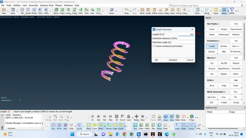
Spring (0.5)
-In this below screenshot of the spring we can clearly see it has more curves in nature.To get the geometrical properties i have been incresed the resolution by giving 0.5
Meshing for spring :
-This is how the meshing looks alike by providing the target length
-Provide advanced front meshing algorithm for this component the reason is to provide uniform mesh length throughout the geometry since it is more curve in nature.
mesh deck module > mesh generation > advance front mesh.
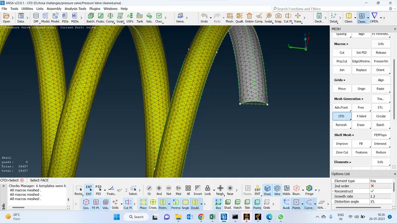
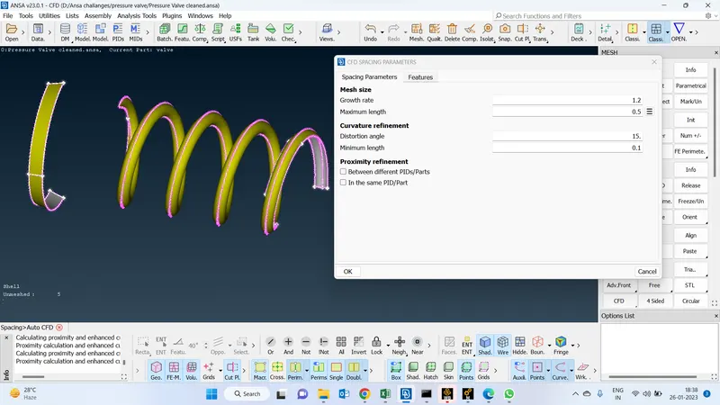
Target length for spring :(0.5 to 0.1 )
-Go to the utilities> mesh parameters> provide target length of max length (0.5) and the min length(0.1)
-By giving the minimum target length we can clearly capture the meshing parameters of the geometry
-If the meshing of the component is good then we can get a better solution at the end of the post-processing
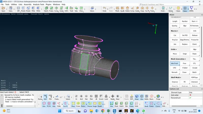
Advance front mesh (Algorithm):
For the below geometry, i have chosen the advance front mesh algorithm so that we can maintain uniform mesh elements throughout the geometry
Length perimeters for the selected faces (1) :
-Increased the mesh resolution to 1 from 2 so that we can capture the geometrical parameters in a better way where ever the geometry has more curves in nature
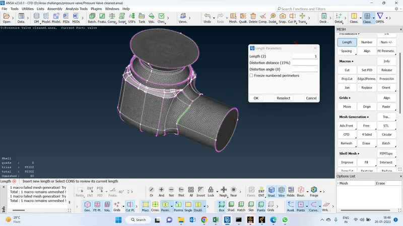
Used cfd algorithm for the below faces :
-For the below-selected parts, I have chosen the CFD algorithm so this algorithm automatically adjusts the element size of the geometry based on its nature if the geometry is flat it will consider higher in the element size if the geometry is more curvature in nature it will go and decrease the element size.
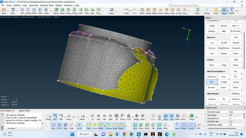
Quality criteria :
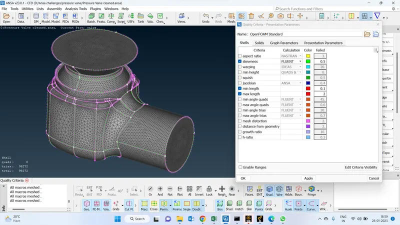
-Once finishing the meshing we will check the quality criteria of the elements based on the solver we are going to use for post-processing
Utilities > Mesh parameters > define min length(0.1) & max length(2) and skewness 0.5
-If the skewness value is close to 0 we can say the quality of the mesh is good if it is near 1 or more we can say that the quality of the mesh target length we have given is not suitable for this geometry.
-By defining the target length the mesh size is going to fall within this limit only.
-No of elements is also based on the target length and the algorithm we choose
-If the geometry is orbitary in shape we have to go with the finer mesh to capture the physical properties.
-If the geometry is flat and not that much orbitary in shape we can go with the course mesh or the maximun elemnet size to decrease the time taken to converge the solution.
-I we want to capture more Xactly accurate solution we will have to go with the finer mesh to capture all the physical parameters exactly
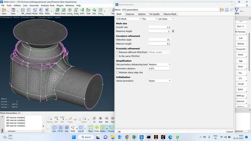
Mesh parameters :
-Reconsidering the target length based on the system specification and went maximum length is 1 and the minimum length is 0.1
Check quality criteria :
-Once after completing the meshing we will have to check the quality of the mesh we have given to geometry is proper or not.
-to check the quality criteria go and click the hidden function it will automatically show the quality parameters we have the option to keep the required quality criteria and we can make inactive the remaining.
-Once we click on the hidden function it will get automatically highlighted the off elements which means it will highlight the elements which are not in fall under the defined criteria.
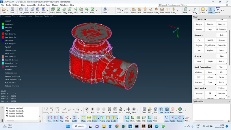
Increase the maximum length of mesh parameters to 6 :
-We can see we have 600 off elements which is in our geometry
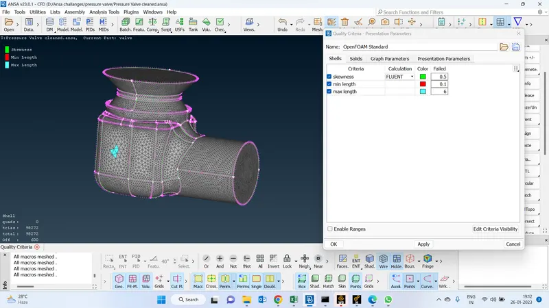
To remove the quality criteria (off elements) :
-To increase the quality criteria of the geometry by decreasing the off elements we will have right click on the off elements and select the reconstruct the and run so that it will reduce the off element in the geometry by redefining the geometry
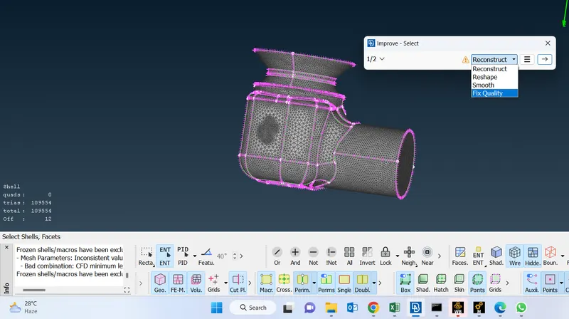
Final geometry without off elements :
By reconstructing and redefining multiple times we will be able to get resolve the off elements
-We can do it manually also if we have very less bad elements by clicking Grids >move option
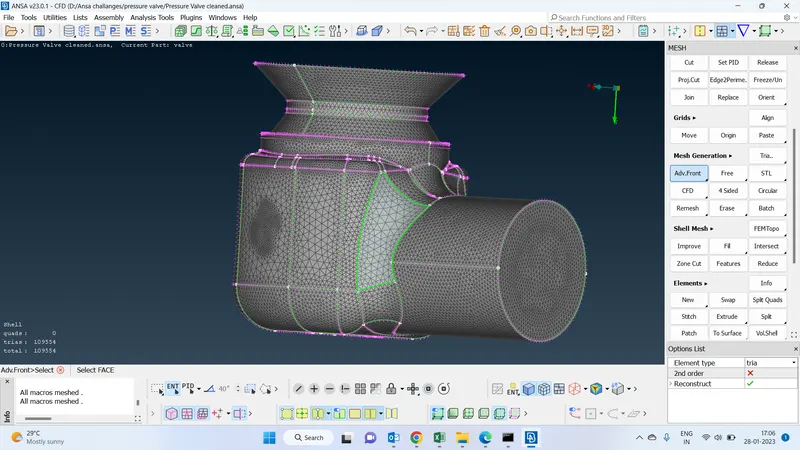
Final geometry after meshing -https://drive.google.com/file/d/1B13NGJkxeJ0cMHXa1_ifeBhDXydSU_la/view?usp=share_link