ANSA - Batch Meshing of Mann Hummel Assembly
Aim :
-Make a Detailed Report on Batch Meshing of Mann Hummel Assembly
-Explain the step-by-step procedure used for Batch Meshing including the snapshots
-Geometry should be error-free
-We are approaching a batch type of meshing in this particular challenge another way of meshing.
We do batch meshing if we have more pids in one geometry to provide different types of target lengths based on the complexity of the pid.
-If the complexity of the pid is more we have to go for a minimum target length to capture the geometry properties.
-If the complexity of the pid is less we have to go for a maximum target length to capture the geometry properties. by doing this we can save the simulation time in post-processing since we are doing refinement only at the required regions. so it is more than enough to capture the physical properties of the geometry at the walls by providing the boundary conditions.
-Doing more refinement for all the parts is not necessary until and unless we are going for the exact solution. We will have to consider the time taken to complete the simulation and also consider the system specification to run the simulation. if we don't have a good spec device it is hard to do simulations.
Initially, batch meshing has been done with all the PIDs at one go
Load the geometry and check the errors :
-Initially, we will have to load the geometry.
-Check the errors by using the check manager function if there are any errors in the geometry we will have to clean it up and go for the meshing process.
- Increase the resolution of the geometry mesh module > perimeter > length(1) by incresing the length we can capture the ge
-perform orientation to identify the fluid flow region.
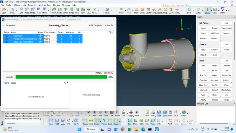
2. Batch mesh :
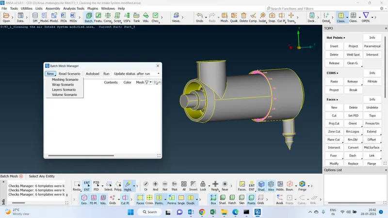
-Perform the batch meshing
-go to utilities > batch mesh manager > New > Meshing Scenario > crate new scenario and works on the meshing process.
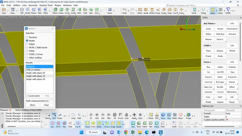
Find the smallest distance between the two nodes in the geometry :
-Find the smallest distance between any two nodes in the geometry baseed on that we will have to go with the target length.
then only we will be able to get the geometry features properly.
- Go to utlities > measure > nodes and select the node points and find ou the distance.
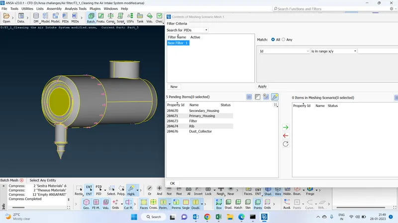
Assign the contents or pids
go to utilities > batch mesh manager > New > Meshing Scenario > create a new scenario and works on the meshing process.
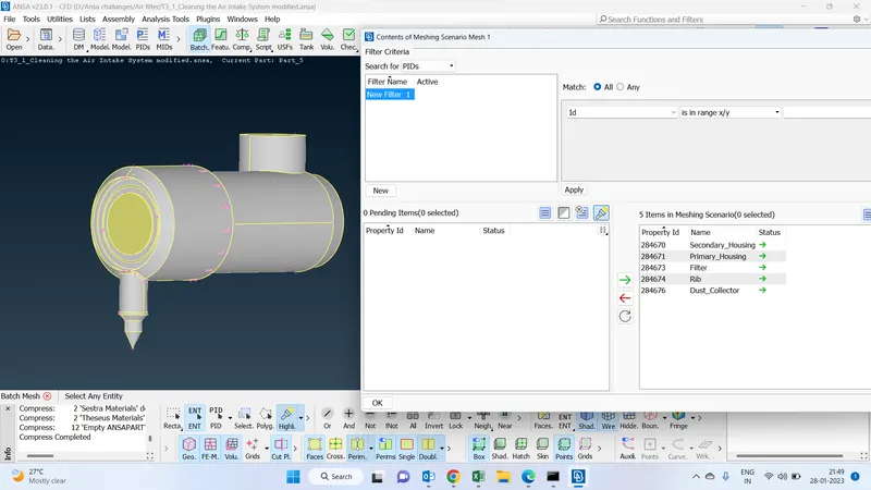
Click on contents and add the pids to the meshing scenario so that we can perform meshing performance only to the added pids.
After assigning :
-This is how it looks after assigning pids to the meshing scenario.
Target length given based on understanding the geometry :
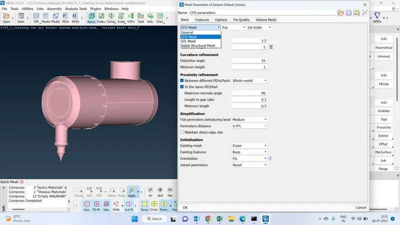
-Since we are performing meshing to all the parts we are using cfd algorithm.
-maximum length is 3 and the minimum length is 1 and also enabling the proximity refinement to both the same pids and also the between the different pids also. by giving this mesh size will elements will into this range.
-the value of the length of the gap ratio is 0.3 and the minimum length is 0.5 by giving these values we can make a finer mesh in those regions to capture the flow properties
Provide quality criteria :
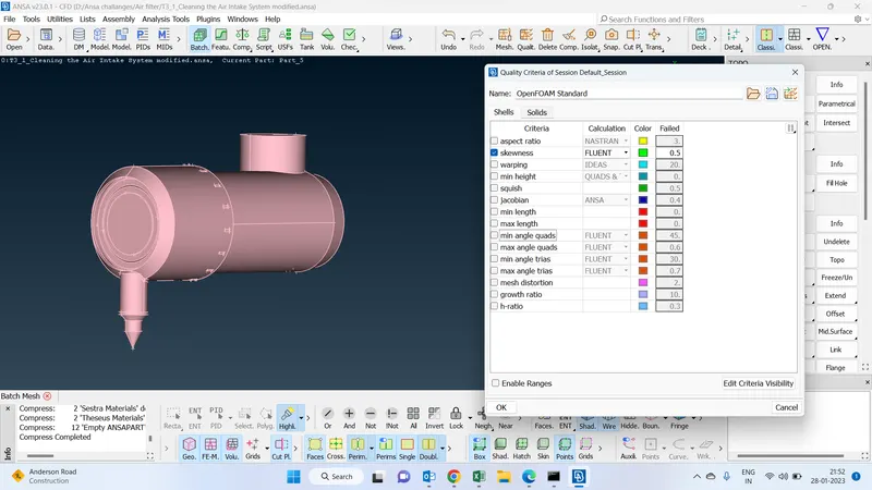
-Enabling skewness in quality parameters by giving 0.5 and disabling the remaining all.
-So those off elements will get if the length of the edge size is more than o.5 will have to adjust and get rdi off this errr so we will come out of this off elements error.
Run :
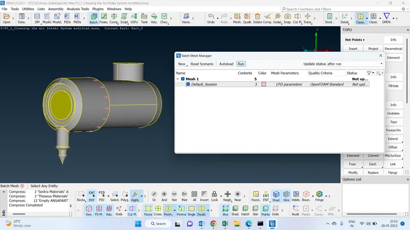
once after setting the meshing properties we will have to run the operation
Proximity :
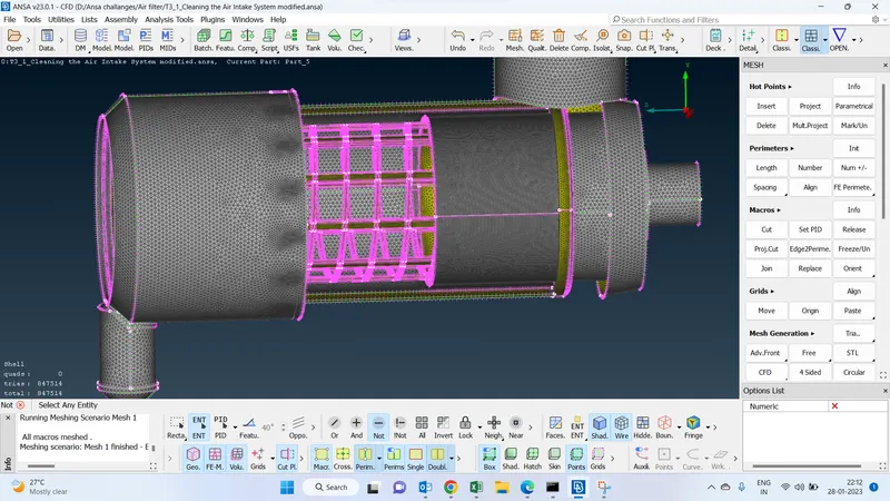
-This is how the meshing generates after meshing the geometry since we are enabling the proximity refinement we can clearly observe where ever the distance is less from one PID to another pid we can the finer refinement
Final Geometry :
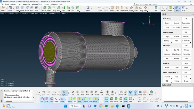
-Below geometry refers to the final view of the geometry of batch meshing.
Create multiple mesh scenarios for 1 geometry :
SCENARIO 1
Filter mesh :
- In this batch mesh we are performing three scenarios in one geometry for different pids by giving different target lengths based on the complexity of the pids.
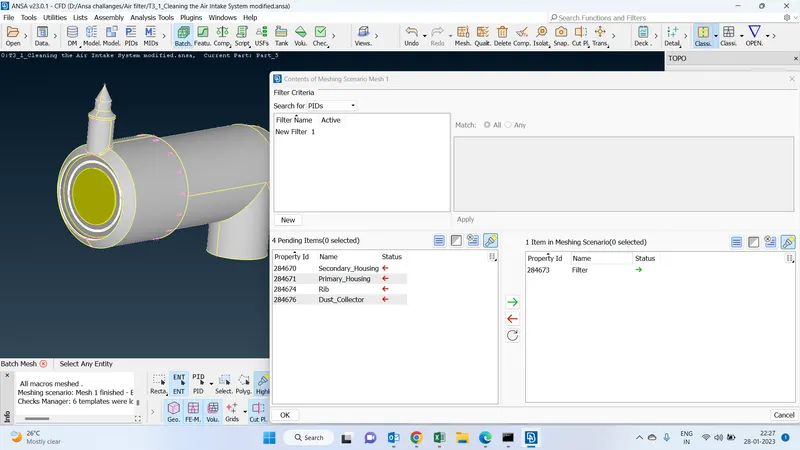
-Create 1st mesh scenario and add contents to the meshing scenario
- Filter is the first content we are adding in 1st meshing scenario.
CFD Parameters :
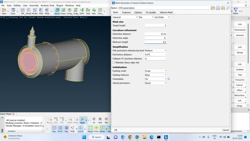
-Went with general mesh since we are dealing with one pid
-Target length has been given as 2
-Minimum length as 0.5 based on the complexity of the geometry
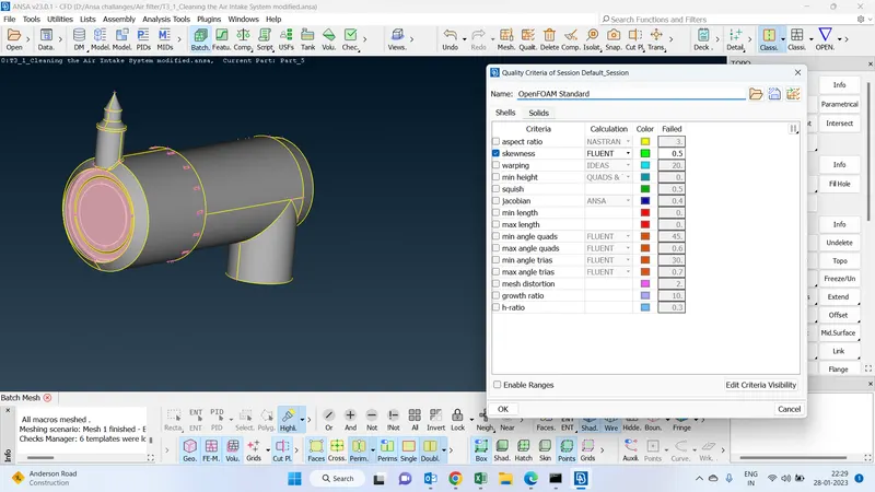
Quality criteria :
skewness criteria of the quality have been enabled in quality.
MESH SCENARIO 2 :
Rib mesh :
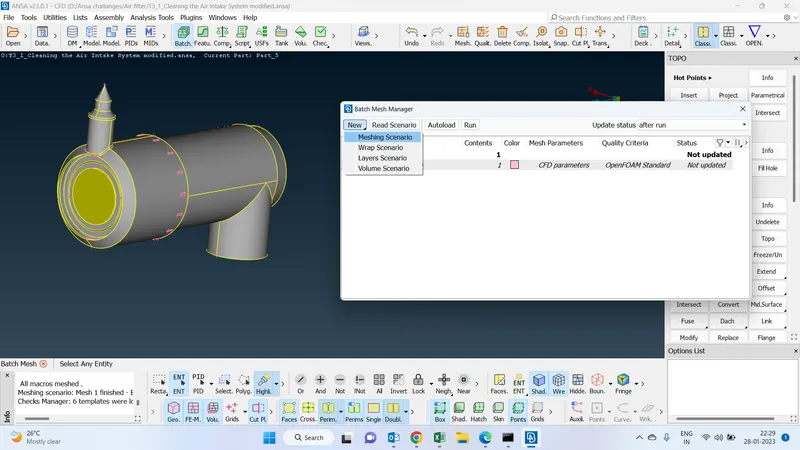
-In Meshing scenario 2 we are performing for rib
-Go to the meshing scenario create a new one
Rib mesh :
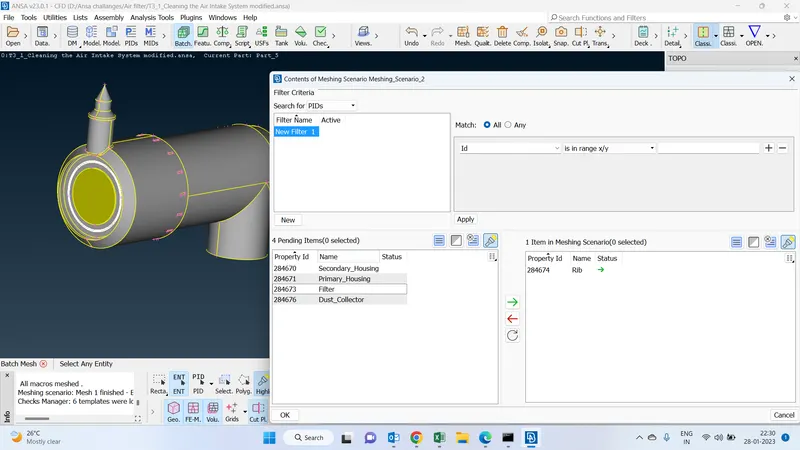
-Add rib to the contents by clicking on contents in meshing scenario
CFD parameters for rib :
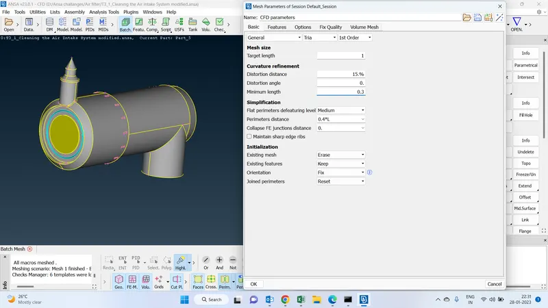
-Set the CFD parameters as per the complexity of the Geometry
- We will have to find out the minimum distance between any two points and consider that distance specify the target lenth and the minimum length.
Quality criteria for rib
Quality criteria of the rib, we enable only skewness 0.5
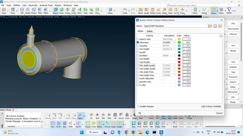
MESH SCENARIO 3 :
Mesh remaining all :
dust collector
primary housing
secondary housing
We will have to create a 3rd meshing scenario
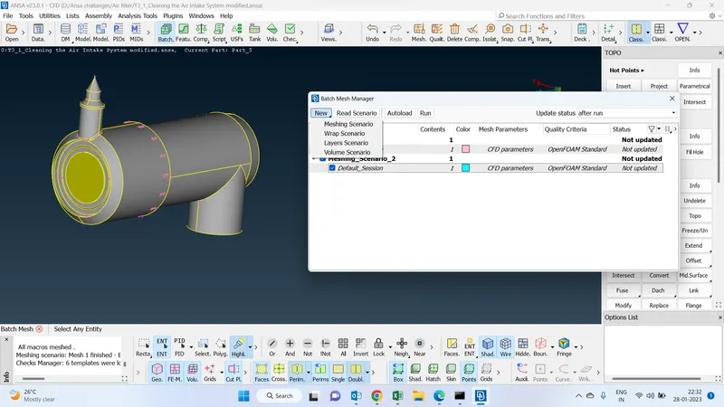
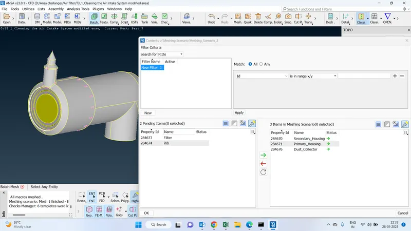
Messing :
Add all the 3 remaining pids in this meshing scenario contents
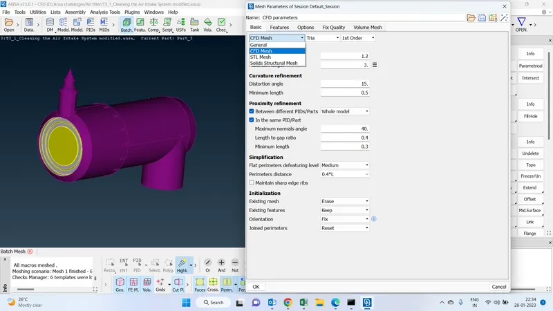
CFD parameters :
Since we are considering all th pids in one scenario i have selected cfd mesh for better mesh
- Target length has been fixed maximum length as 3 and the minimum length is 0.5
-Enabled proximity refinement to the same and the different pids by giving a minimum length 0.3.
Quality criteria :
Quality criteria are set to 0.5 for skewness
Run :
once after creating all the 3 scenarios and set the parameters we will have to run and to the meshing
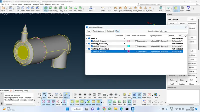
Final Geometry :
This is how the geometry looks like once after running
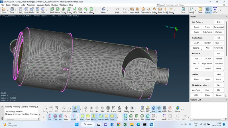
RIB After mesh :
Since we have taken the best target length we were able to capture the geometry features meaning fully.
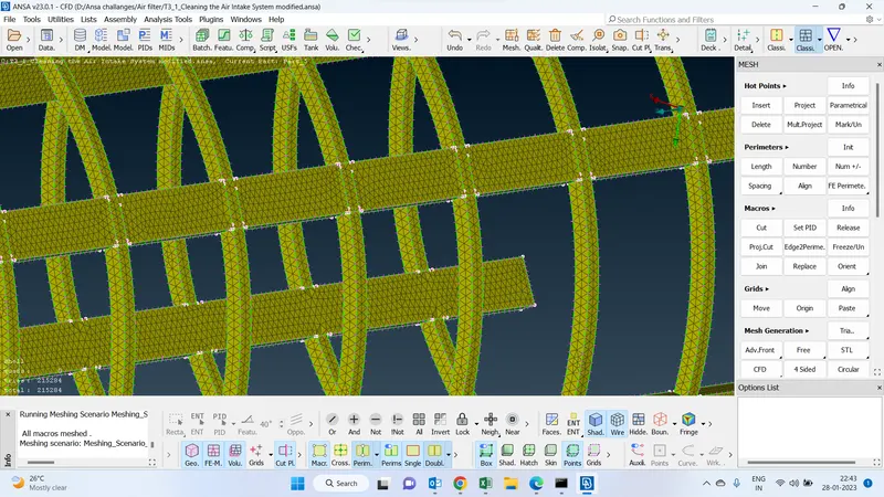
Filter mesh :
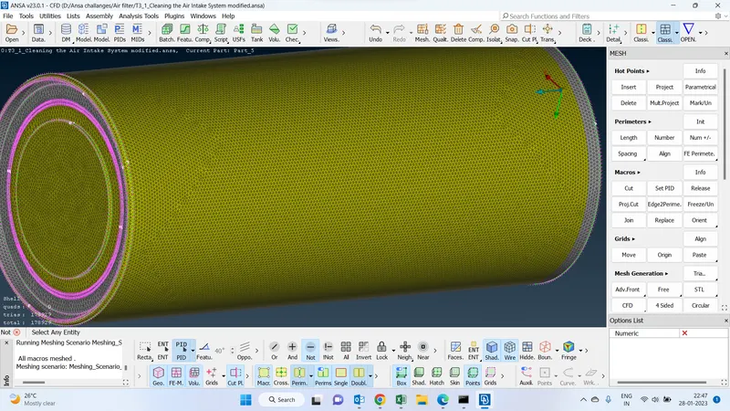
All other three -primary housing, and secondary housing, dust collector :
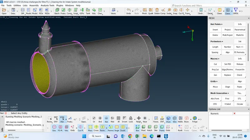
check quality criteria :(Skewness)
By clicking on the hidden function we will be able to check the quality criteria and find out the off elements
we have got the off elements in this geometry.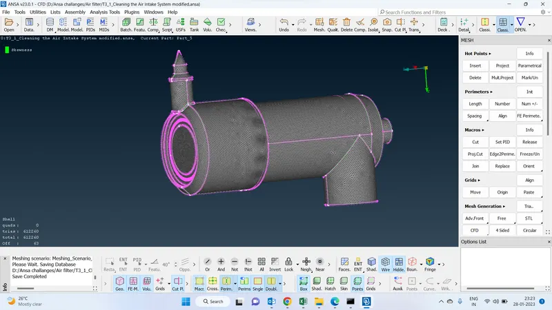
Improve :
to improve the quality of the geometry by clicking the reconstruct option we will be able to reduce the off elements
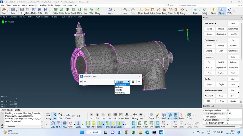
improved the off elements :
These are the areas where the off elements raised
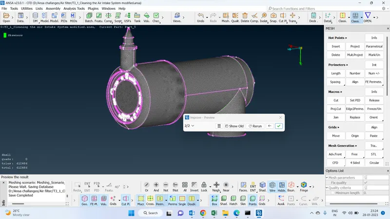
Final geometry after clearing the half elements :
This is how the geometry looks like once after clearing all the off elements.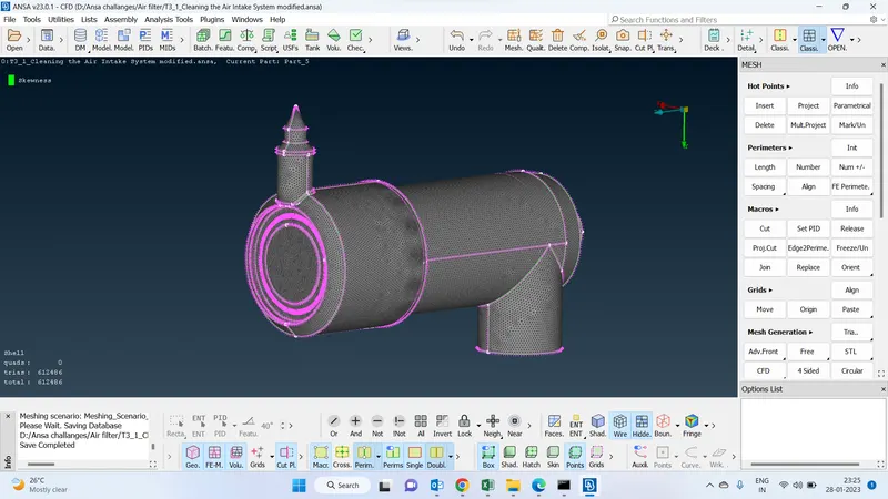
drive link :https://drive.google.com/file/d/1K7AL8qusw6ykQXE37XM_jPeQe4Ure9NF/view?usp=share_link