ANSA - Advanced Meshing of Turbocharger
Make a Detailed Report on Geometry cleanup,
Surface Meshing and
Volumetric Meshing of Turbocharger
Explain the tools used for the step-by-step procedure.
A significant difference between a turbocharged diesel engine and a traditional naturally aspirated gasoline engine is the air entering a diesel engine is compressed before the fuel is injected. This is where the turbocharger is critical to the power output and efficiency of the diesel engine.
It is the job of the turbocharger to compress more air flowing into the engine’s cylinder. When air is compressed the oxygen molecules are packed closer together. This increase in air means that more fuel can be added for the same size naturally aspirated engine. This then generates increased mechanical power and overall efficiency improvement of the combustion process. Therefore, the engine size can be reduced for a turbocharged engine leading to better packaging, weight saving benefits and overall improved fuel economy.
How Does a Turbocharger Work?
A turbocharger is made up of two main sections: the turbine and the compressor. The turbine consists of the turbine wheel (1) and the turbine housing (2). It is the job of the turbine housing to guide the exhaust gas (3) into the turbine wheel. The energy from the exhaust gas turns the turbine wheel, and the gas then exits the turbine housing through an exhaust outlet area (4).
The compressor also consists of two parts: the compressor wheel (5) and the compressor housing (6). The compressor’s mode of action is opposite that of the turbine. The compressor wheel is attached to the turbine by a forged steel shaft (7), and as the turbine turns the compressor wheel, the high-velocity spinning draws in air and compresses it. The compressor housing then converts the high-velocity, low-pressure air stream into a high-pressure, low-velocity air stream through a process called diffusion. The compressed air (8) is pushed into the engine, allowing the engine to burn more fuel to produce more power.
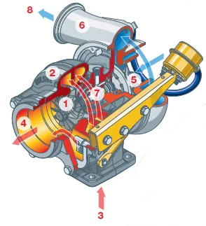
- The turbine wheel
- The turbine housing
- Exhaust gas
- Exhaust outlet area
- The compressor wheel
- The compressor housing
- Forged steel shaft
- Compressed air
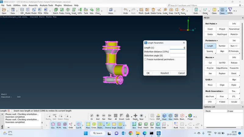
Resolution :
Increasing the resolution after loading the geometry to capture geometrical properties properly.
Mesh deck > perimeters > length gave value 1
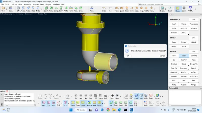
Delete the unwanted faces :
Read the geometry and delete the unwanted faces which is not necessary to keep.
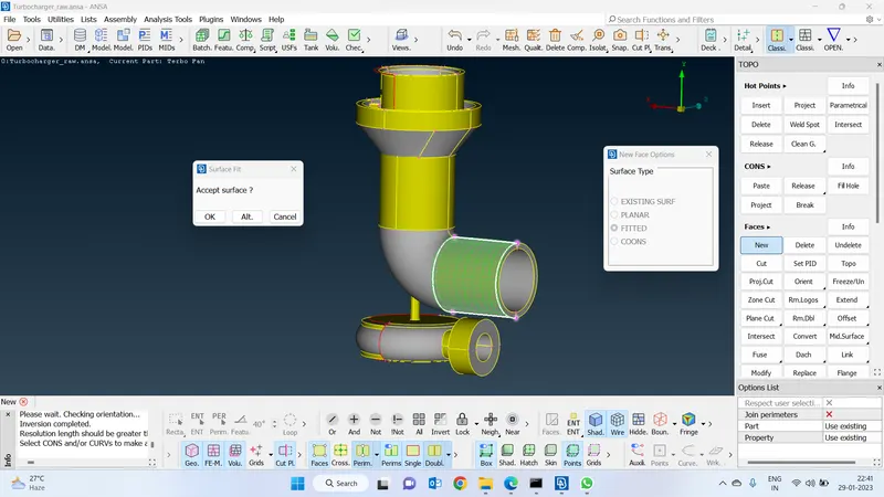
Create a new face :
Faces > crates new > coons or fitted or fill hole option.
Delete the overlap faces :
Delete the overlapped faces
used the faces delete option.
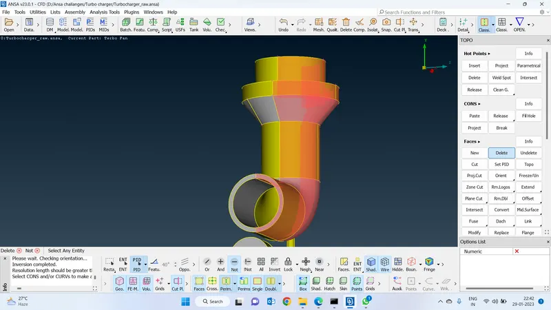
Errors checking after these 2 processes :
-
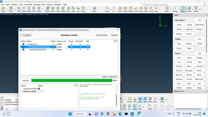
Delete the extra faces by intersecting :
Use the faces intersect option to delete the unwanted faces
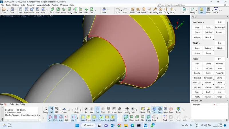
After intersection :
After intersecting delete the unwanted faces. and keep the necessary faces.
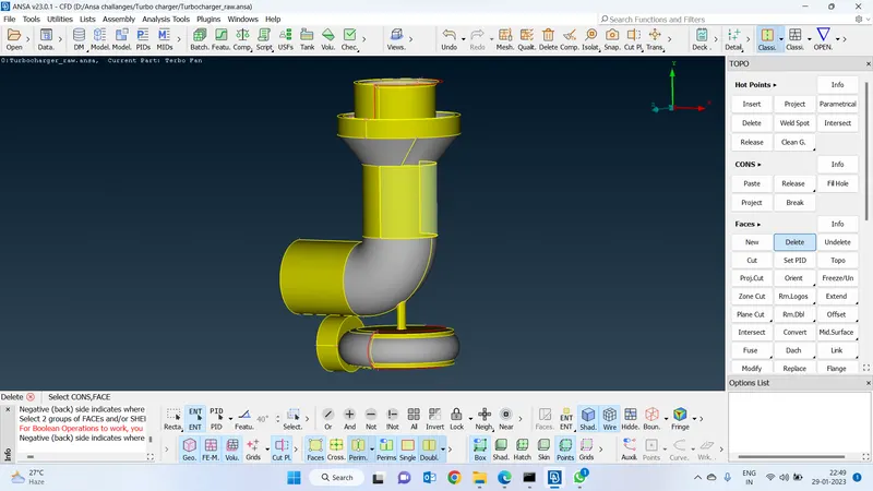
Intersect :
Intersect the top faces with each other and delete the unwanted faces.
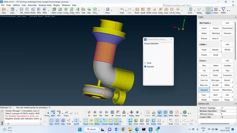
Keep the necessary faces and delete the unnecessary faces :
Select the faces which I want to keep and delete the faces which I want to delete.
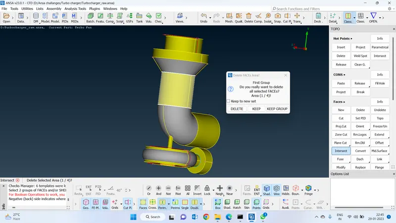
Fill the gap :
-Create a face wherever it's required by used faces coons option.
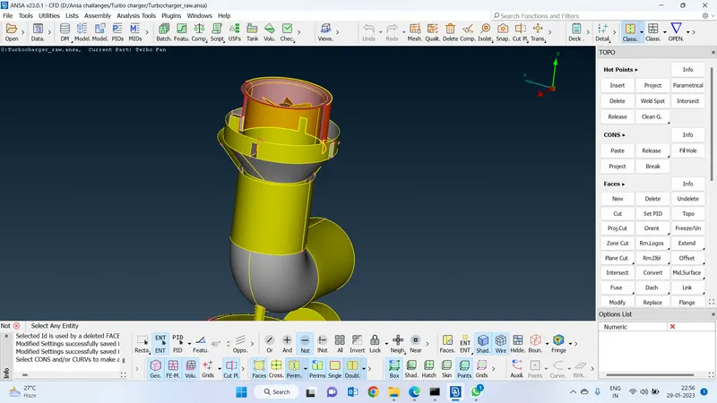
Fill the gap by Creating a hot point :
-Fill the gaps by creating hot points on the coons
-Create a face without closing the small holes which are located inside.
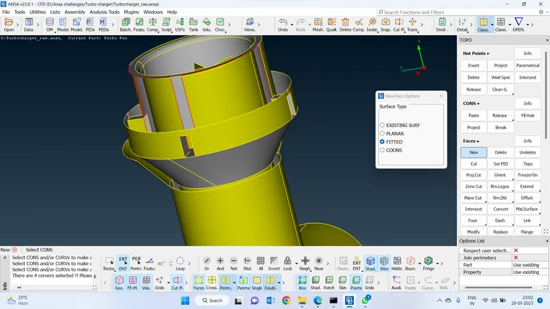
Create a small face:
Create small faces once after creating the big faces nearby
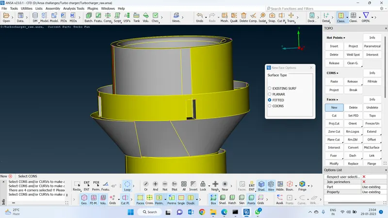
Successfully created a face without closing the gaps :
Successfully created a new face without closing the small holes.
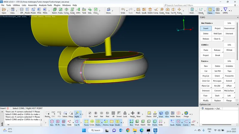
Insert a hot point :
Insert points and create a mirror face on the other side.
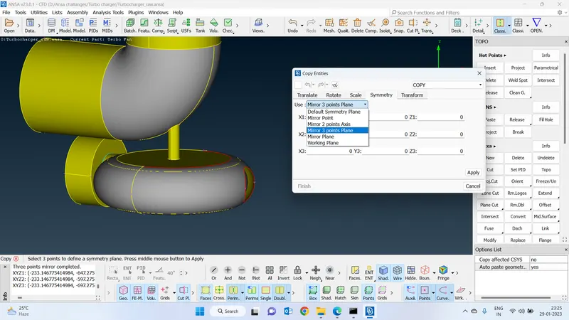
Transform and copy the face :
-Use transform a 3-point plane.
Transform > symmetry> mirror points plane and select the 3 points on the surface where we want to create a new face.
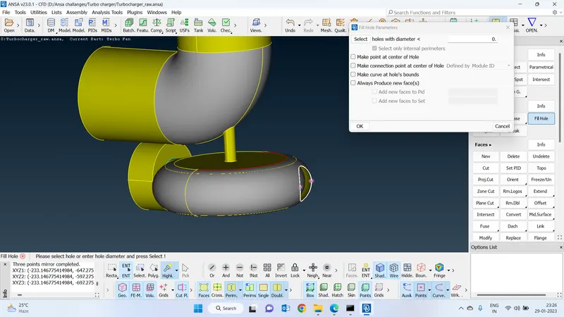
Use fill hole option :
Use the fill hole option to fill the small missed hole
Hit topo to close the single coon errors :
-Select the topo function and select the faces and hit a topo and convert the single coons to doule coons and share the volumetric information properly.
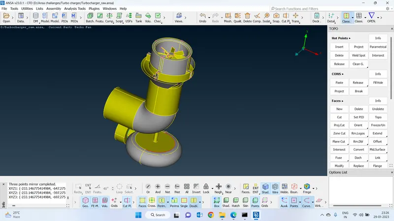
Errors inside parts :
-Clear all the intersections which are having the shaft and also the blades.
-There were lots of faces overlapping on the other
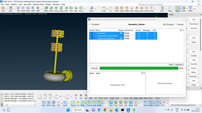
Hit a topo to merge the cons properly :
Hit topo to merge the faces properly.So that unmerged faces will merge properly
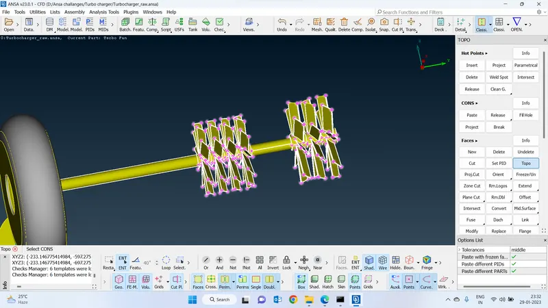
Delete the unwanted faces on the shaft and also the blades :
Delete the unwanted faces and also the overlapped faces so that we can avoid the triple coons in the geometry
-Overlapping faces will cause more no of elements in meshing it is better to remove triple cons
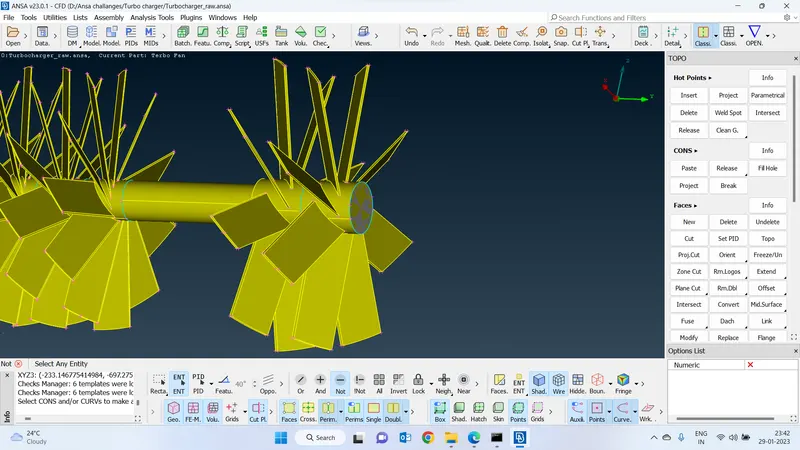
Delete overlapping faces :
-Delete the faces which are intersecting with each other
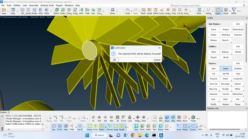
Delete the unwanted face :
-Project the faces with each other and delete the unwanted faces
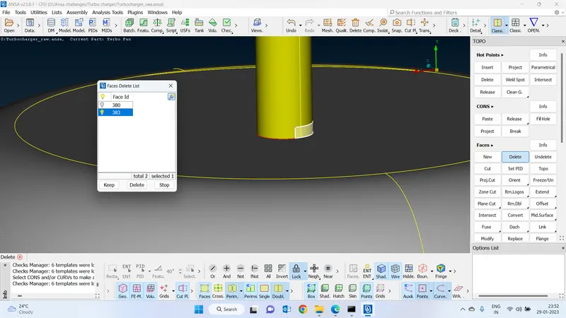
Delete the unwanted face inside the turbine :
-Deleted the unwanted faces inside the turbine.
-We will have to delete wherever the fluid is going to interact.
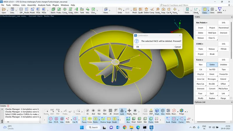
Delete the unwanted face at the turbine side shaft :
Delete the unwanted face or where the fluid is not going to interact.
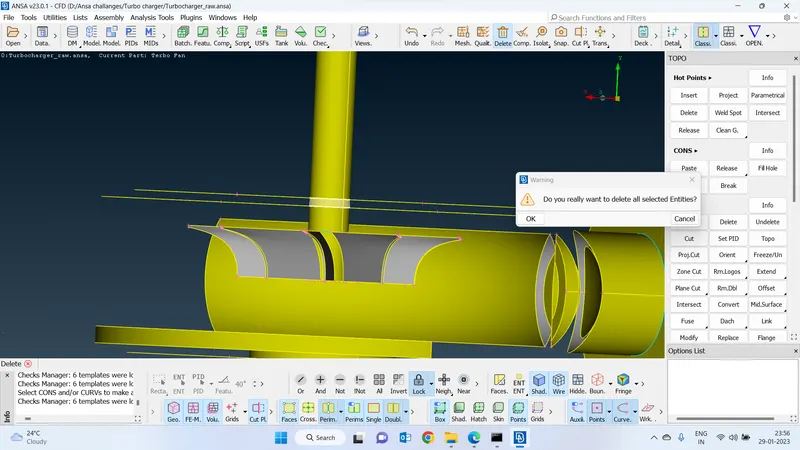
Project the coons with the surface
Project the coons with the surfaces and delete the face
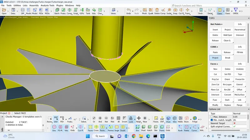
Delete the overlapping faces :
Delete the eoverlapping face after the projection
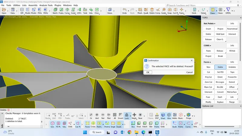
Delete the shaft which is not required inside the compressor :
-Delete the unwanted shaft part which is located inside the compressor
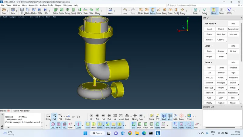
Project the cons with the bar :
-Project coons with the bar and seperate that shaft porion and delete it.
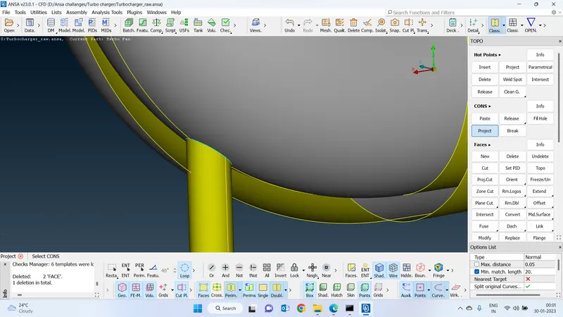
Error-free :
-We have cleared all the intersection errors
-now we van see the geometry is error free.
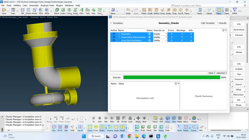
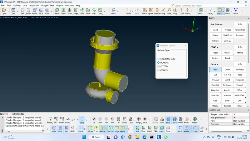
Create a water-tight model by closing all the openings :
create a watertight model to make the geometry leakproof by closing all the faces which are opened by using new faces planar option
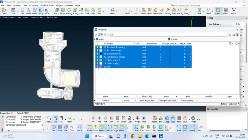
Create pids for all the geometry :
Create a meaning full pids for the components which are present inside the turbocharger geometry.
-Which is useful to provide the meshing and also to assign the boundary conditions
Surface meshing :
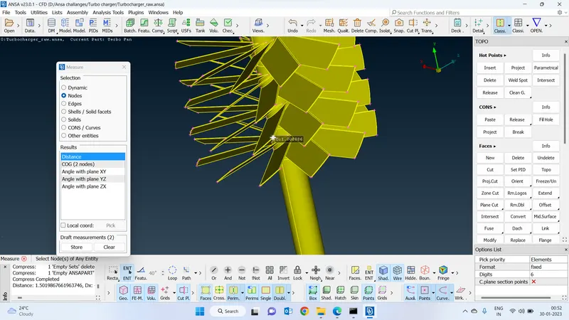
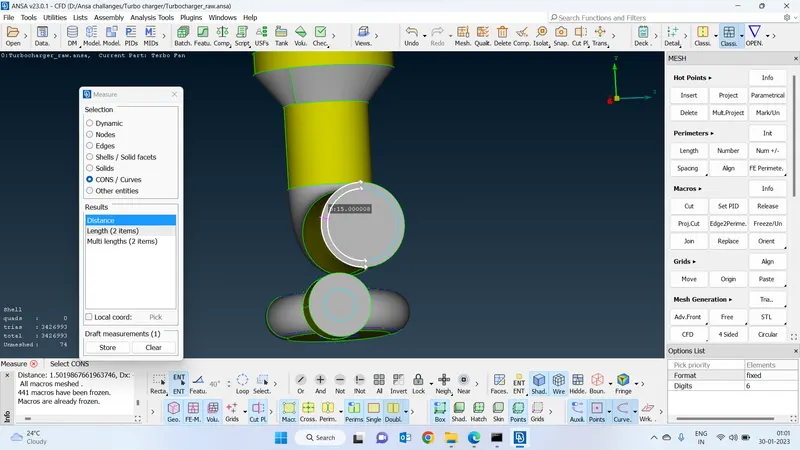
Find out the minimum length between any two nodes of the geometry :
-find out the minimum distance between any two nodes in the geometry based on that we will have set a target length for meshing purposes
-If we provide a greater target length than the minimum distance between any two nodes then there will be a lot of chances to distort the material.
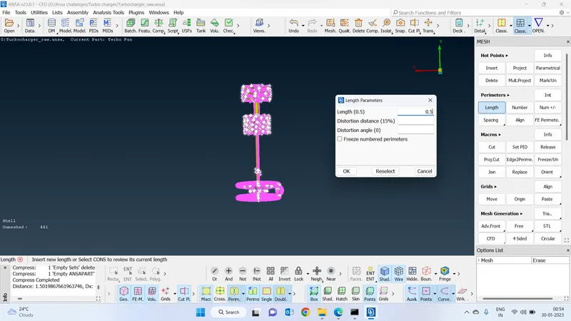
Increase the resolution :
-Increase the resolution since the geometry has nore curvatures and also the smaller faces so that we went with 0.5 resoltion to capture the geometrical errors properly
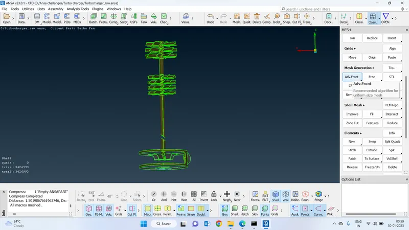
Advance front mesh :
Went with advance front mesh since the complexity of the geometry is high.
This mesh is better to capture the geometric features exactly. and also it will create an equal size of elements througout the geometry
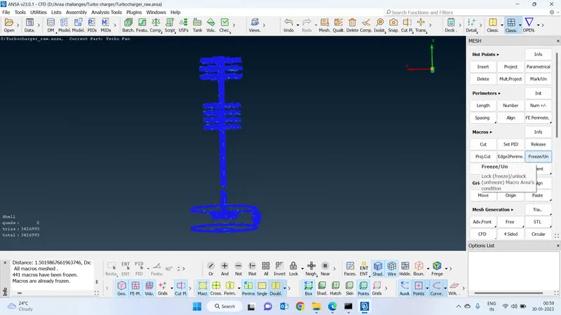
Freeze the inside Geometry :
Freeze the geometry if we freeze the geometry it will help us to do the meshing remaining components without effecting that operation to this component
Consider the outer area and find out the minimum length :
-By considering the outer area fix the target length since the faces are big we can go for maximum target length based on the geometry
Provide auto cfd spacing and fix target length for meshing of the outer geometry :
-Provide the target length by selecting the auto cfd in the spacing optMaximumimum length has been given as 7 and the minimum length has been given 2
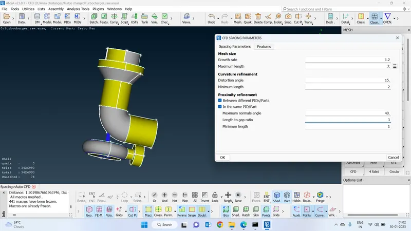
Went with CFD mesh :
-Went with CFD meshing so this algorithm automatically provides the element size based on the size of the face and it will automatically capture the curvature and make the mesh finer.
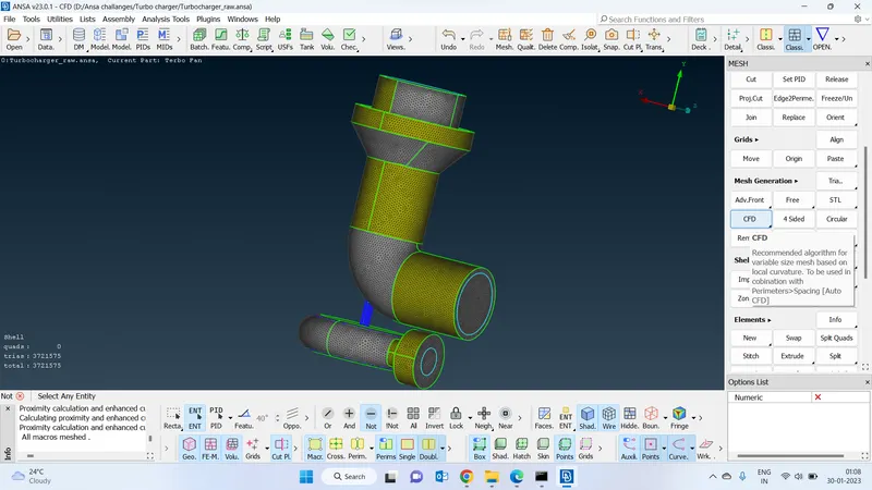
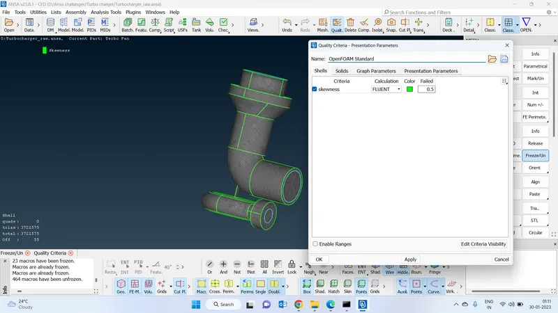
CHECK SKEWNESS :
Check the skewness of the geometry
-go to the quality criteria and select the skewness as default 0.5 and check the skewness
-We can see we have 55 off elements in the geometry.
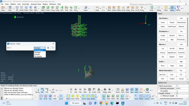
Improve the off elements :
-To improve the geometry meshing and decrease the off elements by selecting the reconstruct option which will automatically
increase the quality of the mesh
Error-free geometry of the Surface meshing :
-We can see there are no off elements in the geometry.
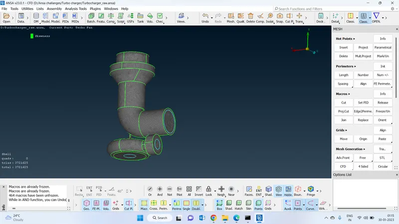
Volumetric mesh :
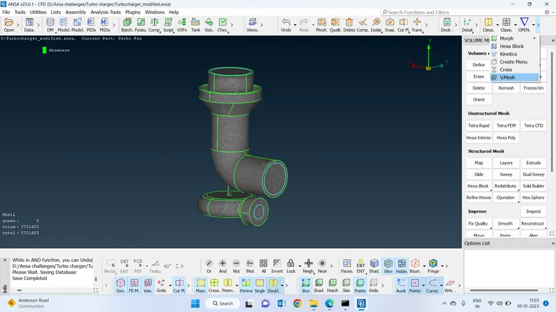
Direction to get volumetric mesh :
Go to the classic mesh deck and expand the function and select the volumetric mesh.
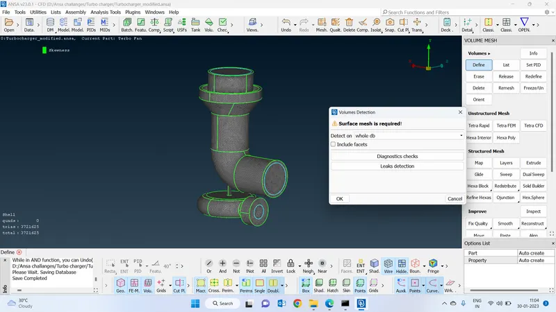
Define the geometry :
Click on define the geometry and define it and click on ok
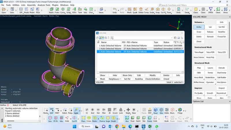
Define the internal parts of the turbocharger :
Which will show the components to do the volumetric mesh
Mesh algorithm used :
Used unstructured mesh algorithm
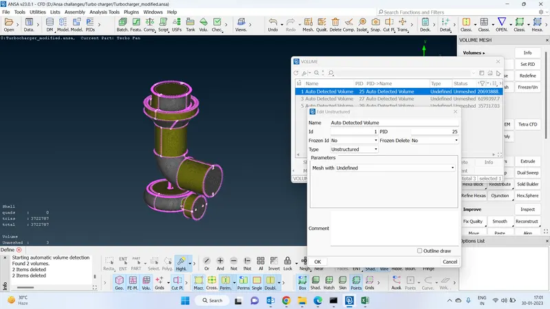
Types of 3d elemetns :
Select the type of 3d mesh and keep the remaining parameters as the default and click on ok.
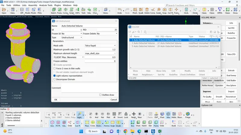
Internal parts volumetric mesh :
Mesh all the remaining parts and do the volumetric mesh by using tria rapid meshing algorithm
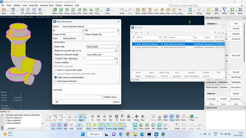
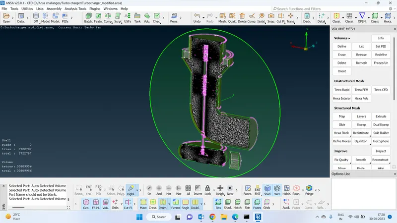
Internal parts volumetric mesh completed :
Completed the internal part volumetric mesh with tria rapid mesh
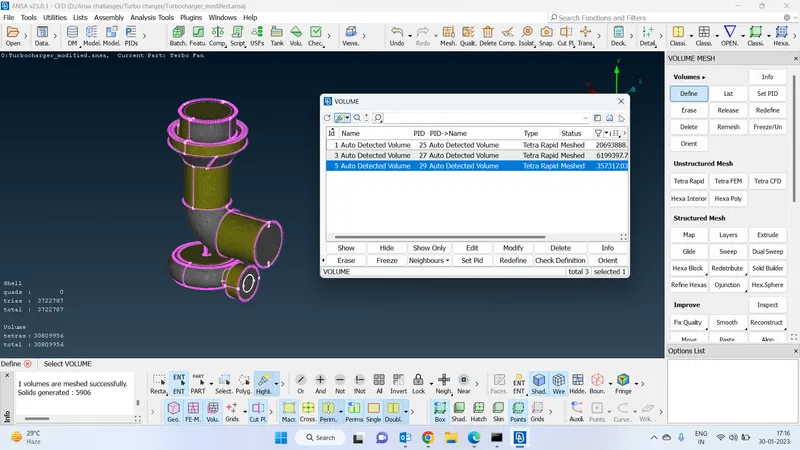
Created a plan for better visualization:
Created cut plane for better visualization purposes we can clearly see the volumetric mesh has been generated with more refined mesh using tria rapid algorithm
Google drive link to the final geometry :
https://drive.google.com/drive/folders/1D7ZAd6M5oTSbMKZd5THiE_v2G9MxG2uI?usp=share_link