Analysis & Design of RCC shear walls in the model using ETABS
Analysis & Design of RCC shear walls in the model using ETABS:
ANSWER:
AIM:
To Run the analysis and design the RCC shear walls (show in the etabs model). The following challenge deals specifically with the shear wall of size 300x1500 at grid A-11 in the structural model.
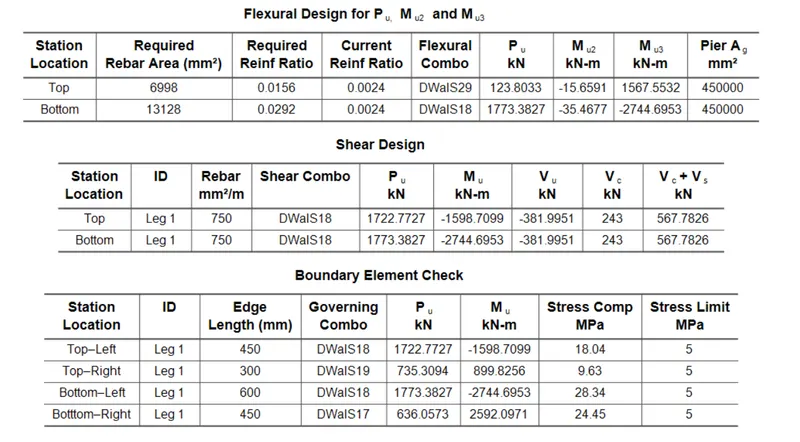
- Extract values of longitudinal steel ratio, boundary element length and shear reinforcing ratio from the design results.
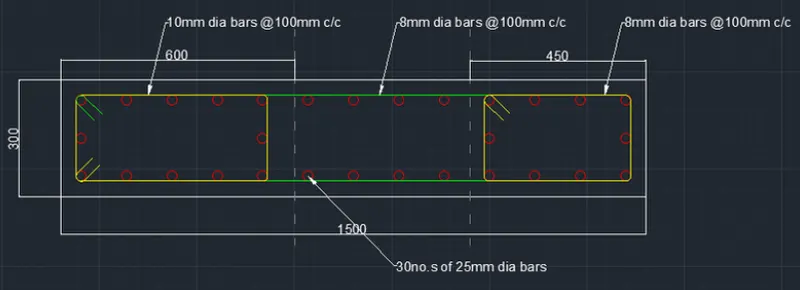
- Provide cross sectional steel arrangement of the shear wall from its base up to terrace, in compliance with provisions of IS 13920 – 2016. AutoCAD application can be used for this exercise. Alternatively, it can be drawn by hand as well.
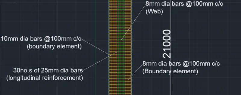
- Provide elevation drawings of the reinforcement details of the shear wall from base up to terrace.
INTRODUTION:
In this challenge we are detailing the rinforcement for shear walls of size 300x1500 at grid A-11 in the structural model. A shear wall consists of detailing of reinforcemnt like vertical and horizontal reinforcement-web and boundary elements. These are subjected to alternative lateral loads (eq).
hence we are design the details of shear walls as per below codal provisions.
- Classification of shear wall as per the clause 10.1.4 of IS 13920:2016.
- Minimum vertical reinforcement within the boundary element from table 1 of section (iii)- as per IS 13920:2016.
- Horizontal reinforcement in the shear wall as per codal provision IS 13920:2016 of table 1-section(iii).
- The providing of maximum dia of rebar of shear wall as per clause 10.1.8 of IS 13920:2016.
- Confining reinforcement spacing for boundary element as per clause 10.4.4 of IS 13920:2016.
- Confining reinforcement Within boundary element as per clause 10.4.4 IS 13920:2016.
- minimum reinforcement in Rc shear wall as per clause 10.1.6 of IS 13920:2016.
PROCEDURE:
- Initially open the ETABS software.
- open the given etabs file.
- the go to the Analysis model.check if there is any errors.

- After that run analysis the model.
- then Go to the Shear wall design in the etabs provided at the top.
- Now select the .and go to the view- view select objects only.
- Then visible of selected columns only.
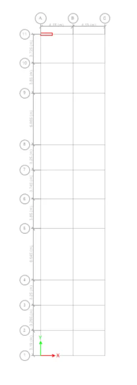
- Then done the shaer wall design in the etabs provided at the top right corner.
- shaer wall design-design preferences.
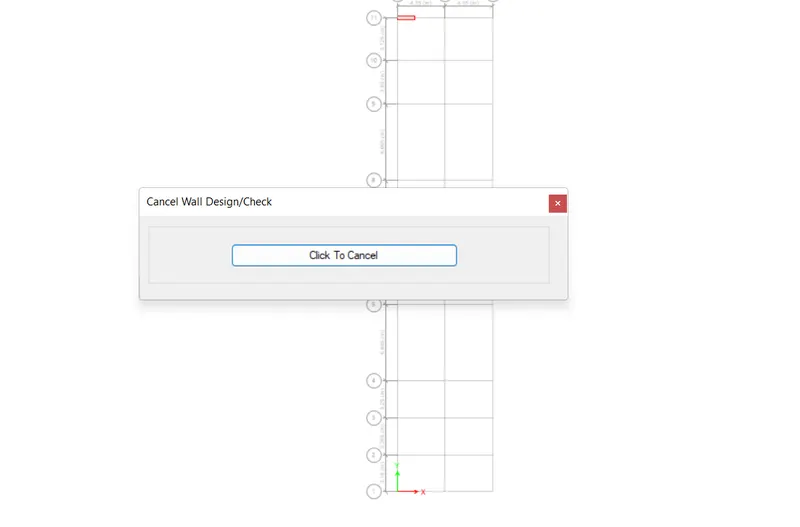
- then change the elevation to A then it visible the both the columns .
- Longtudinal reinforcement:
for A-11 shear wall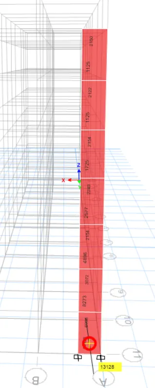
- NOw shear reinforcement:
- For A-11 shear wall
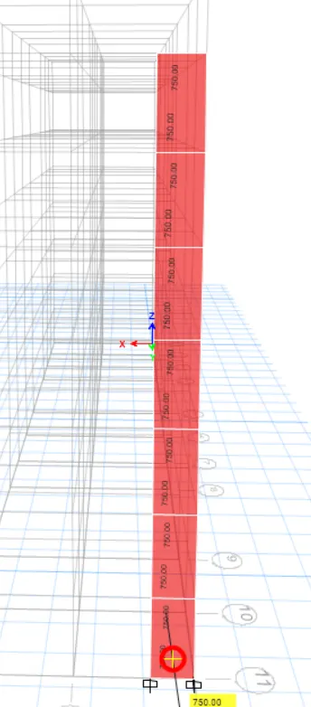
- reinforcement deatils for pier egde or boundary width of shear wall.
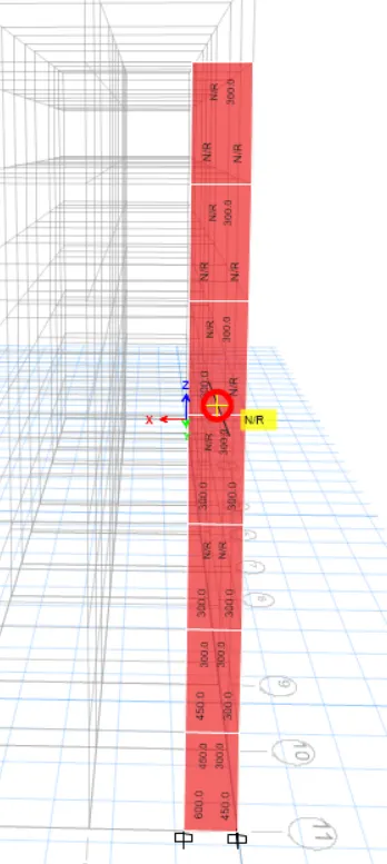
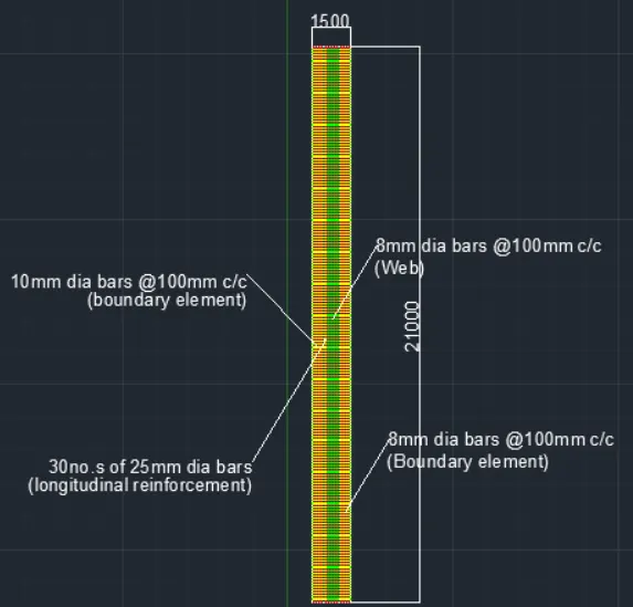
- Now we have Find the longitudinal and shear or transverse reinforcement details for the A-11 shear wall and drawn in the auto cad file as shown in the below figure.
Design summary for the shear wall.
DESIGN CRITERIA:
- Classification of shear wall type as per the clause 10.1.4 of IS 13920:2016.
`h_w/l_w= 21000/1500=14>2`
From the above we can say as the Type of shear wall as slenderwall. - Longitudinal Reinforcement:
- From the etab results it shows the maximum longitudinal or vertical reinforcement=`13128 mm^2`
now we are providing the 25mm Dia of bar with ast=`490mm^2`
henece to find the no.of bars `13128/490= 28`bars+2bars forsupport of confinement reinforcement.totally 30nos of bars are provided.
Total provided for longitudinal reinforcement=`13720mm^2` - Vertical reinforcement in boundary region=`0.008*1500*300=3600mm^2`
we provided at left side region=`5390mm^2`
we provided at right side region=`4410mm^2`hence safe at boundary zones. - Vertical reinforcement in web region=`0.0025*1500*300=1125mm^2`
But we provided is3920mm^2 hence safe.
- From the etab results it shows the maximum longitudinal or vertical reinforcement=`13128 mm^2`
- Shear / Horizontal reinforcement:
- From the etabs results we should provide `750mm^2`
But we provided 8mm`phi`@ 100mm c/c.So AST provided =`1000mm^2` - Shear reinforcement for boundary edges as per clause10.4.4 of IS 13920:2016.From the given formulae.
`A_(sh)=0.05 *s_v*h*f_(ck)/f_y`
Where `s_v=100mm`
h=600-80=`520mm`
`f_(ck)=25n/(mm^2)`
`f_(y)=500n/(mm^2)`
Hence obatined - For left side =`ash=0.05*100*520*25/415 =156mm^2`2 legged.
So provided 10mm dia of bars @ 100mm c/c. - For Right side =`ash=0.05*100*370*25/415 =111mm^2`2 legged.
So provided 8mm dia of bars @ 100mm c/c.
- From the etabs results we should provide `750mm^2`
Now showing the detailing of reinforcement of shear wall A-11 in auto cad drafting.
RESULT:
- The given etabs model is checked and anaylsed by using the etabs software.
- For the given model we have carried out the shaer wall design.
- stuided the maximum area of steel required for lognitudnal and shear reinforcements at confinement zone for A-11 shear wall.
- we have provoded the sufficient area of steel as per their codal provisions of IS 13920:2016.
- For the details we have also draft the drawing in the auto cad.
REPORT:
Calculations are shown above.
| DETAILS | SHEAR WALL | REQUIREMENT | PROVOIDED | SAFE |
| longitudinal/ vertical reinforcment | A-11 | |||
| 1.total area of steel required. | `13128 mm^2` | `13720mm^2` | ok | |
| 2.confinement zone @ right | `3600mm^2` | `4410mm^2` | ok | |
| 3.confinement zone @ left | `5390mm^2` | ok | ||
| 4. @ web zone | `1125mm^2` | `3920mm^2` | ok | |
| Shear / horizontal reinforcement. | A-11 | |||
| 1.shear reinforcement | `750mm^2` | `1000mm^2` | ok | |
| 2.confinement zone @ right | `156mm^2` | So provided 8mm dia of bars @ 100mm c/c. | ok | |
| 3.confinement zone @ left | `111mm^2` | So provided 10mm dia of bars @ 100mm c/c | ok |