Analysis & Design of RCC shear walls in the model using ETABS
CHALLENGE WEEK 9
ETABS
Question no.1: The etabs file for a G+6 building is provided. Run the analysis and design the RCC shear walls (show in the etabs model). The following challenge deals specifically with the shear wall of size 300x1500 at grid A-11 in the structural model.
Answer:
- Aim:
- To review the supplied Etabs model
- To gather design details of the model.
- Resolve the said issues in the model
- To follow suggested parameters.
- Procedure:
- As like the week 7 and 8 challenge we are going to take the existing supplied model.
- In week 7 and 8 models we were modelling for columns and beams with a G+4 building.
- Whereas in week 9 we are suppplied with a G+5 building where we have to model for shear wall design.
- Hence as like before we are inserting the existing model into the software.
- After inserting the model into the ETABS software we are going to process the suggested analysis.
- In the inserted model we need shear wall design
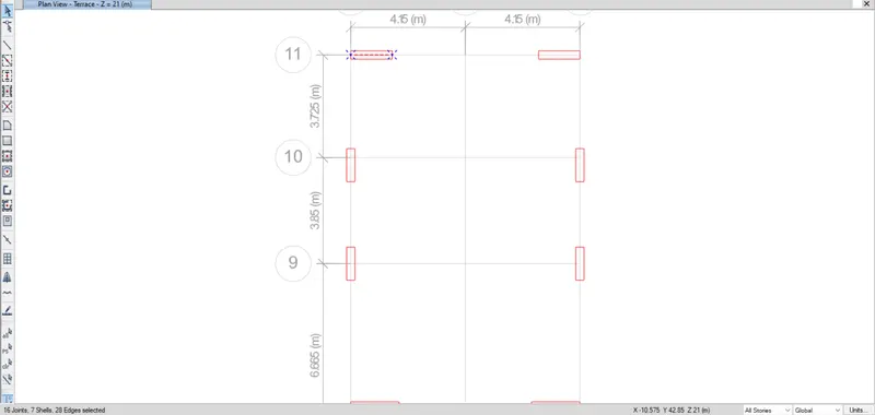
- Hence we are picking up the specified shear wall as specified in the challenge.
- The shear wall picked is in the grid 11
- Picking the shear wall is by selecting all stories option to select all the shear walls in the specified grid.
- The selected shear walls are shown below.
]
- Let us view the elevation of the shear wall picked up.
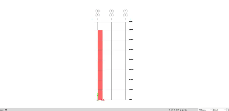
- And the next thing we will be checking before the analysis is the pier label assignment in the shear wall.
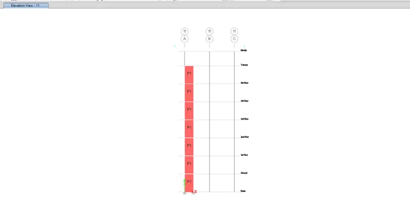
- After the selection of the shear walls and checing the necessary data we are going to run the analysis.
- After the analysis we ge the report of the model.
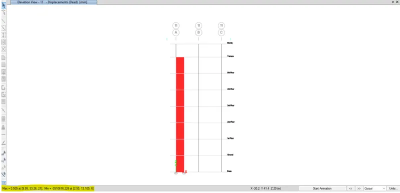
- After this the model is taken to shear wall design.
- The shear wall design is shown below.
- Which shows the pier longitudinal reinforcing
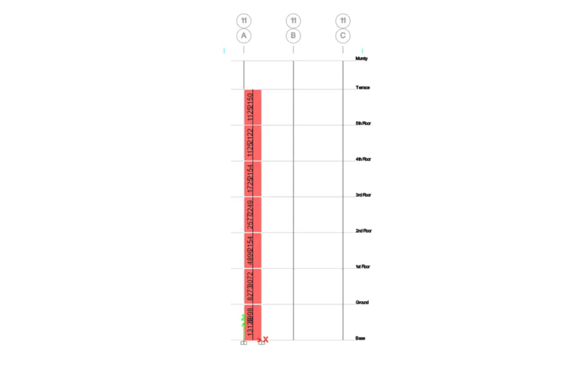
- After this we will see the pier Edge/boundry zone reinforcing
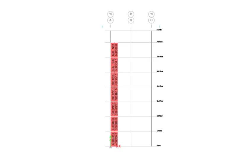
- After this the Pier shear reinforcing is shown
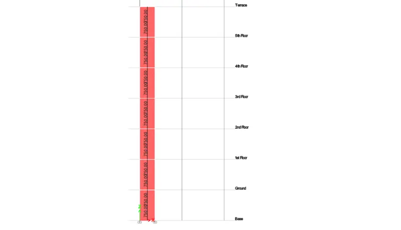
- After the reinforcing detail extraction we are set to drafting the reinforcement design drawing.
- So before that let us view the elevation so that we can draw through the whole building with story heights.
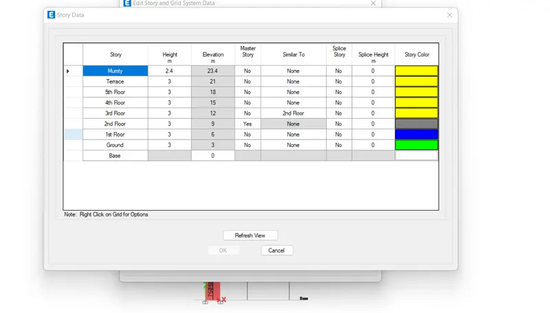
- After the reinforcing details we are begining with teh specification and guidelines check on the design of the shear wall.
- Classification of shear wall as per IS 13920-2016 Clause 10.1.4
Slender wall
hw / Lw = 21000/1500 = 14>2
- Min. net vertical reinforcement as per IS 13920-2016 Table-1
= 0.0025+0.01375(300/1500) which we multiply with the top view of the wall as it is vertical reinforcement we get
= 2363mm^2
- Min. Vertical reinforcement within boundary element table-1
1440mm^2 on left (600mm width boundary element)
1080mm^2 on right(450mm width boundary element)
- Minimum horizontal reinforcement in shear wall per IS 13920-2016 Table 1
(ρh)min = 0.0025 + 0.5((hw/Lw)-2) (ρh – 0.025)
ρh = 750/(300*1000) = 0.0025
hw = 21000
Lw = 1500
(ρh)min = 0.0025 + 0.5 (21/15 – 2) *0
(ρh)min = 0.0025 which is the same 750 mm2/m
- Max dia of the rebar for shear wall as per IS 13920-2016 Clause 10.1.8
1/10th of wall thickness = 300/10 = 30mm
where commercial rebar dia used to be 25mm which can be adopted
- Confining reinforcement spacing for boundary elements as per IS 13920-2016 Clause 10.4.4
- 1/3 of min member dimension = 300/3 =100mm
- 6 times smalles main rebar = 6*25=150mm
- 150mm permissible if vertical bars are spaced at maximum 200mm
max spacing of confining reinforcement in boundary element 150mm
- Confining reinforcement within boundary element as per IS 13920-2016 Clause 10.4.4
Ash = 0.05 Sv h fck/fy
Sv = 150mm, h= 1000mm
Ash = 452mm2
- With the above procedure we are detaining the reinforcement of the shear wall.
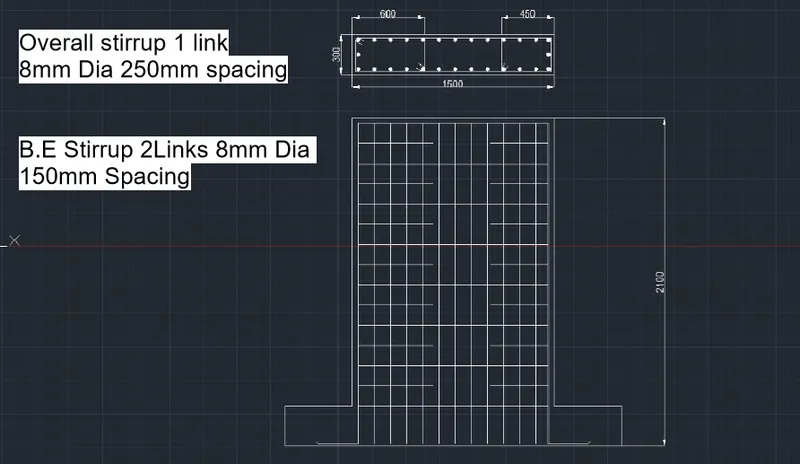
- The drafting is done in autocad and is shown below
- Result:
- The model was inserted.
- Resolutions was derived.
- Required design details of teh shear wall was shown
- The required details and drawing were shown