Analysis & Design of RCC shear walls in the model using ETABS
Q. The etabs file for a G+6 building is provided. Run the analysis and design the RCC shear walls (show in the etabs model). The following challenge deals specifically with the shear wall of size 300x1500 at grid A-11 in the structural model.
- Extract values of longitudinal steel ratio, boundary element length and shear reinforcing ratio from the design results.
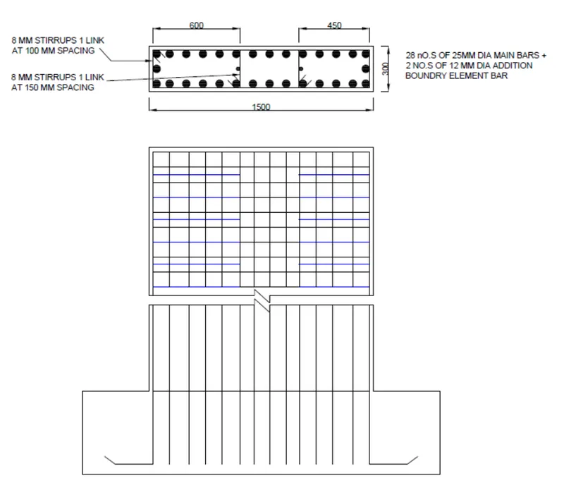
- Provide cross sectional steel arrangement of the shear wall from its base up to terrace, in compliance with provisions of IS 13920 – 2016. AutoCAD application can be used for this exercise. Alternatively, it can be drawn by hand as well.
- Provide elevation drawings of the reinforcement details of the shear wall from base up to the terrace.
Ans:
Aim of the Challenge:
- To Extract values of longitudinal steel ratio, boundary element length, and shear reinforcing ratio from the design results.
- To provide a cross-sectional steel arrangement of the shear wall from its base up to the terrace.
- To provide elevation drawings of the reinforcement details of the shear wall from the base up to the terrace.
Shear Wall:
- A shear wall is a vertical element of a system that is designed to resist in-plane lateral forces, typically wind and seismic loads.
- A shear wall resists loads parallel to the plane of the wall & specially designed to resist lateral wind and seismic forces in high-rise buildings.
Procedure:
- Open the downloaded etabs file.
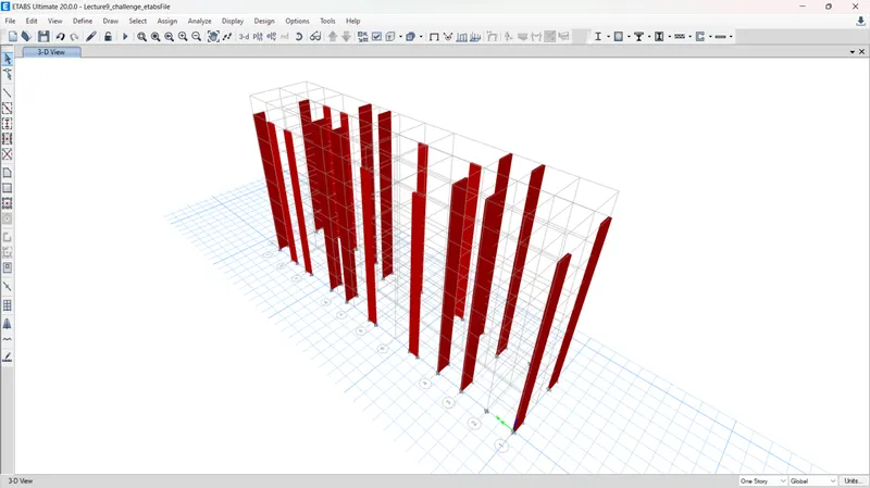
- The 3D render view.
- To analyze go to the plan at terrace level.
- Select the required SW A-11.
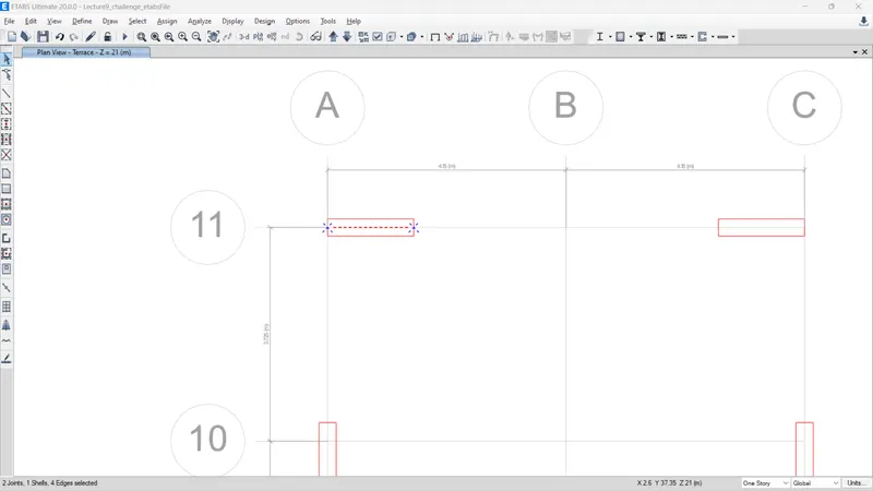
- Right-click & Show selected objects only.
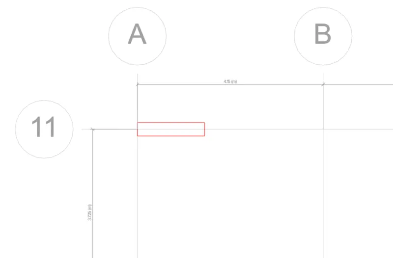
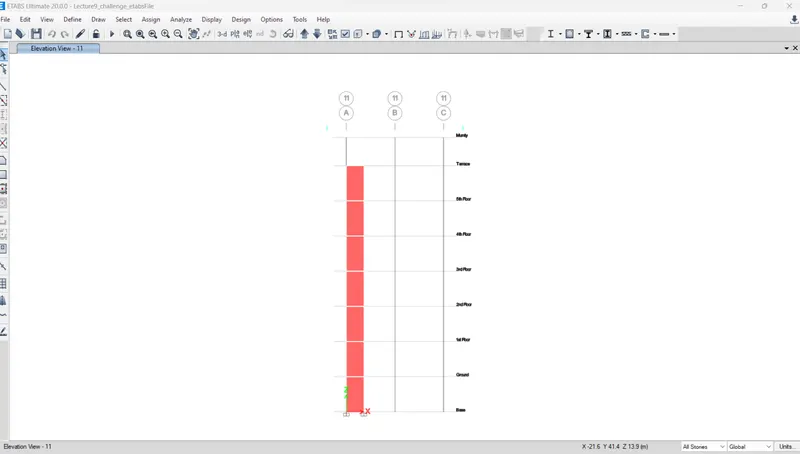
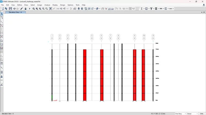
- For viewing the elevation along the grid level.
- Go to run analysis.
- Click on shear wall design & start design check.
- Longitudinal Reinforcement
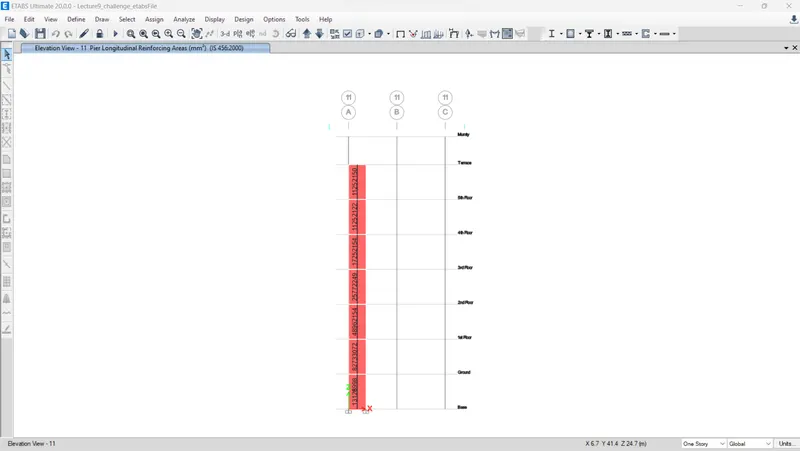
- We can change into pier shear reinforcement by clicking on the drop down menu of the --> display design info --> Select pier shear reinforcement -->ok
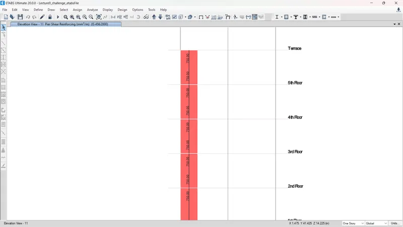
- Again go to -->drop down menu of the --> display design info --> pier edge/boundary zone widths -->ok
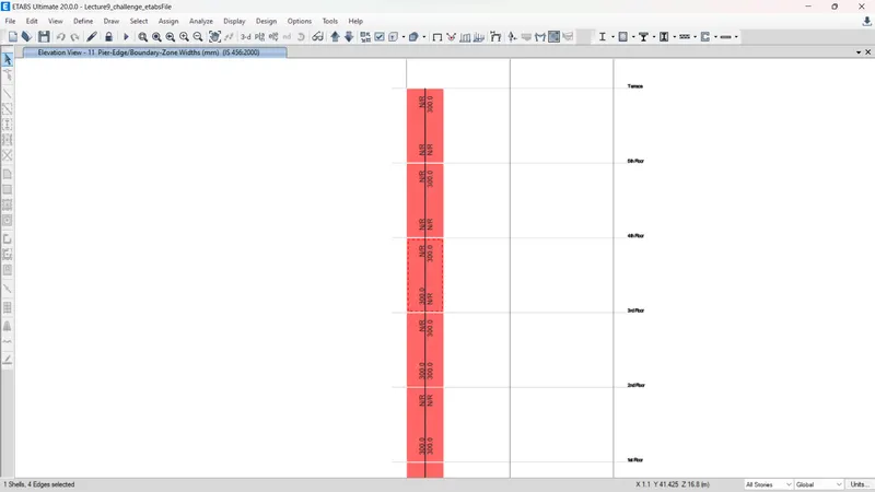
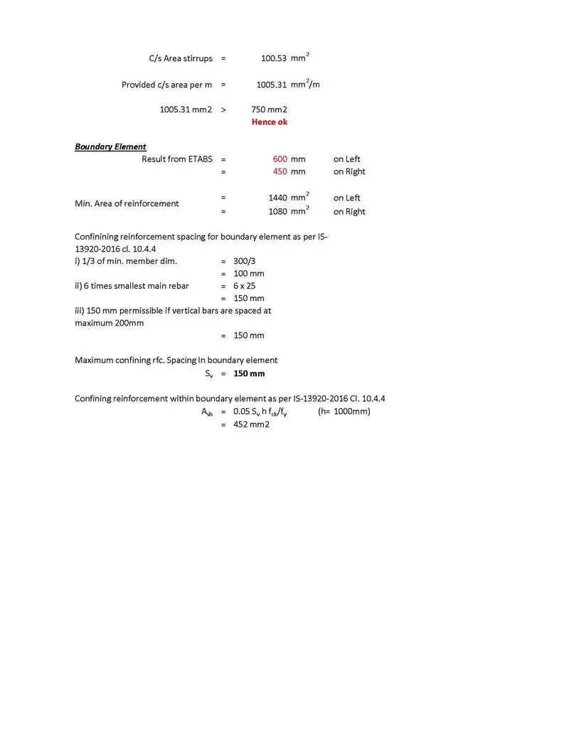
- The above shot represents that the boundry element length requirement at one side of the base as 600mm & another side as 450.
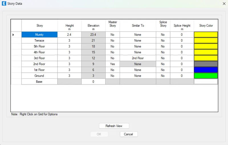
- The height or elevation of each floor is noted.
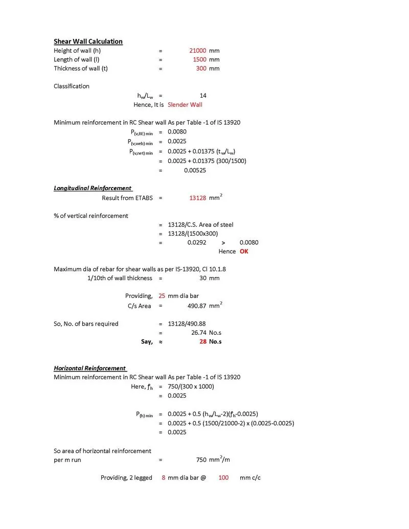
Detailing Calculation:
Guidelines for shear Wall- The greater of below
- Minimum reinforcement for shrinkage & temperature
- Ultimate limit state design rear requirement
- Ductility rebar requirement
RESULT:
- Provided the extracted values of longitudinal steel ratio, boundary element length, and shear reinforcing ratio from the design results.
- Provided cross-sectional steel arrangement of the shear wall from its base up to the terrace, in compliance with provisions of IS 13920 – 2016.
- Designed the RCC shear wall using the design results from the ETABS file.
- Provide elevation drawings of the reinforcement details of the shear wall from the base up to the terrace.