Analysis & Design of RCC shear walls in the model using ETABS
- The etabs file for a G+6 building is provided. Run the analysis and design the RCC shear walls (show in the etabs model). The following challenge deals specifically with the shear wall of size 300x1500 at grid A-11 in the structural model.
Aim:
- Extract values of longitudinal steel ratio, boundary element length and shear reinforcing ratio from the design results.
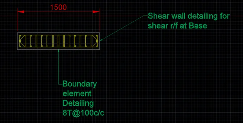
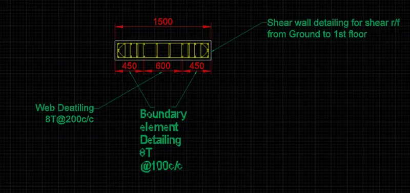
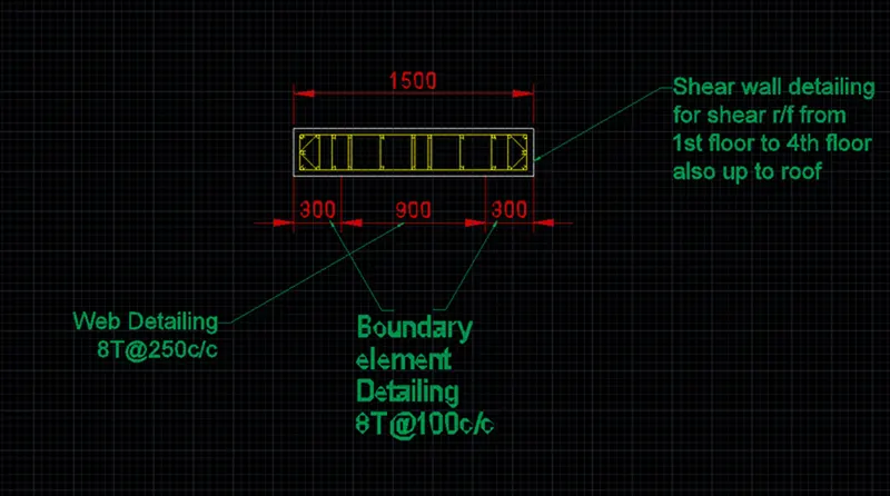
- Provide cross sectional steel arrangement of the shear wall from its base up to terrace, in compliance with provisions of IS 13920 – 2016. AutoCAD application can be used for this exercise. Alternatively, it can be drawn by hand as well.
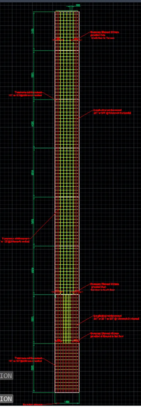
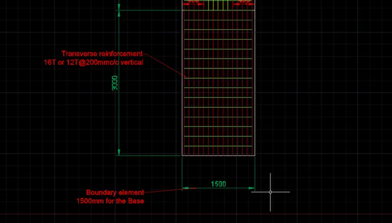
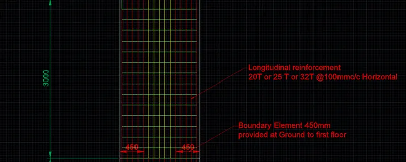
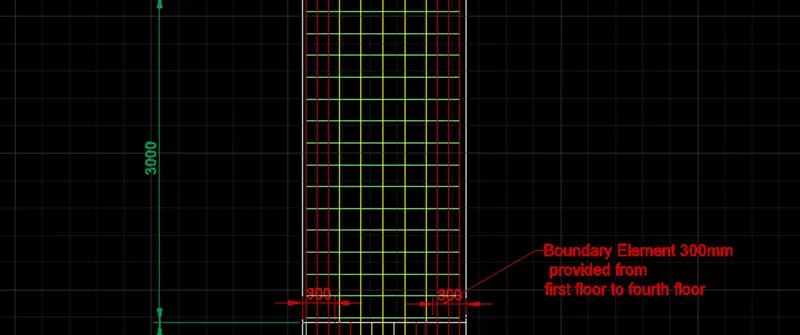
- Provide elevation drawings of the reinforcement details of the shear wall from base up to terrace.
Procedure:
- Download the attachment and open it in ETABS.
- Check the model for errors.
- Click f5 to run the analysis.
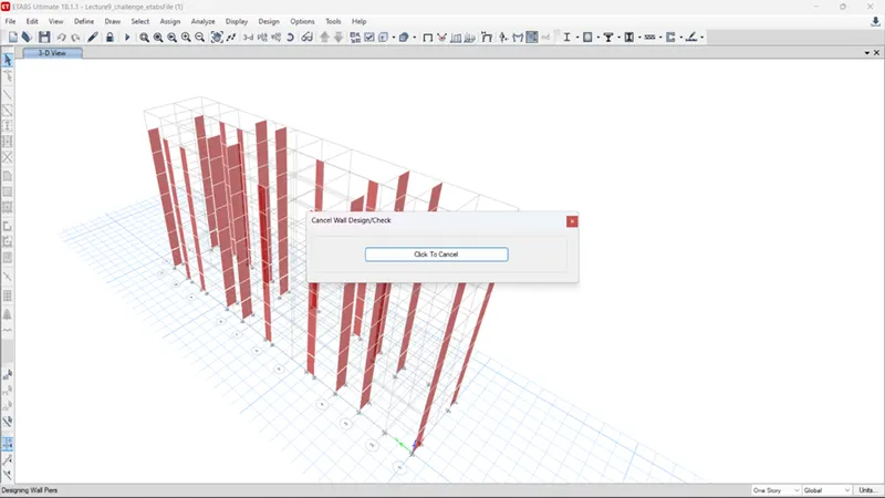
- Then start the design of shear wall from the drop down menu of shear wall design.
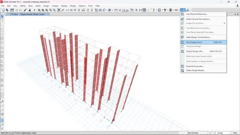
- Find the failures by selecting the display design info from the Shear wall design drop down menu and select Identify P-M failure.
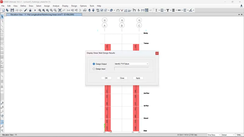
- In case any failure is present it will be displayed after applying this.
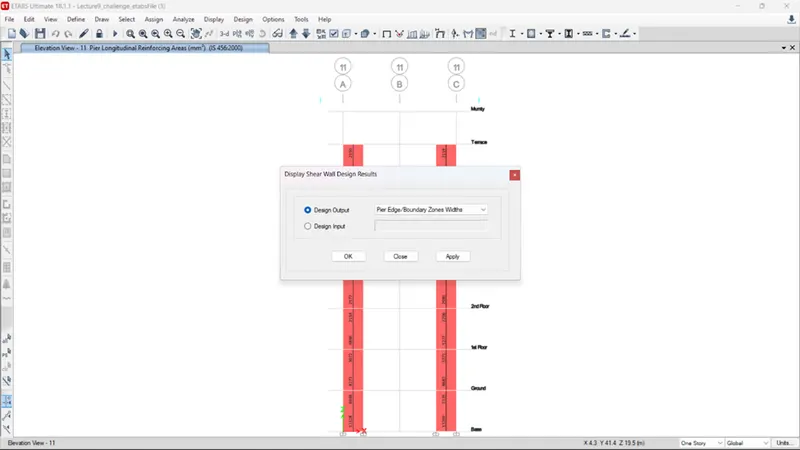
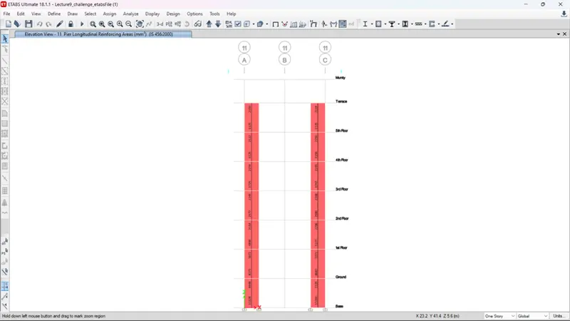
- Then to design the shear wall select pier longitudinal reinforcement from the display design info dialogue box to get the reinforcement info.
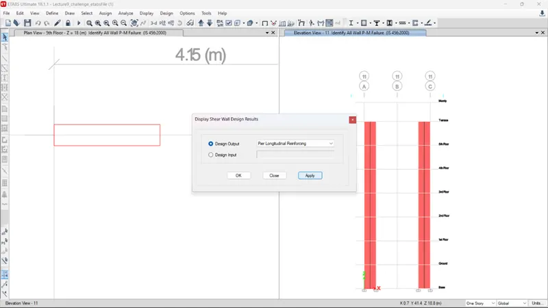
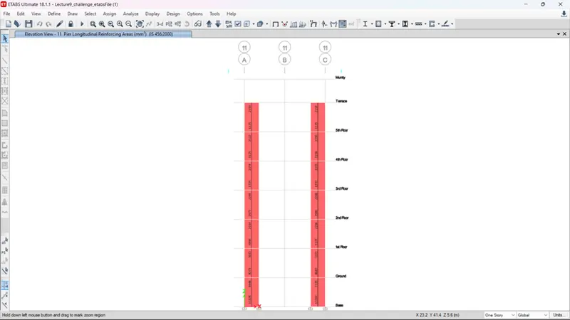
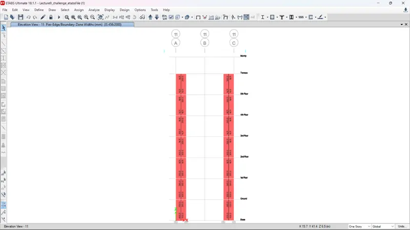
- Next to get the boundary element widths follow the same process as we did to get the longitudinal reinforcement and select Pier edge/boundary zones widths and apply.
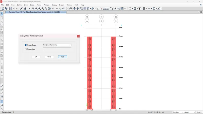
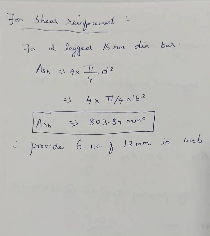
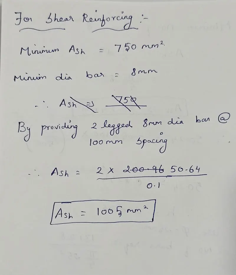
- Similarly get the shear reinforcement details by selecting Pier shear reinforcing from the drop down menu.
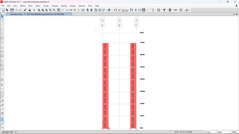
- Now after extracting all the required details we have to follow the clauses given in IS 13940-2016 to provide the cross sectional steel arrangement of the shear walls and draw the reinforcement details of the shear wall.
- The design of the reinforcing walls is assumed to be part of the subsequent Structural Strength System
- Shear walls must be reinforced longitudinally and transversely in the plane of the wall. The minimum bar ratio should be 0.0025 of the total area in each direction. These bars should be evenly distributed over the wall section.
- The minimum thickness of the shear wall is 150mm or more.
- The thickness of the shear wall is 300mm.
- Clause 10.1.8 (1390-2016) tells us that: The maximum diameter of longitudinal steel bars used in any part of a wall shall not exceed 1/10 of the thickness of that part. = 300/10 = 30 mm
- Hence use 25mm dia bar for detailing.
- Maximum distance between reinforcing bars in any direction must not exceed the smallest of a) Lw/5
b ) 3tw
c ) 450 mm
- Length of the wall= 1500mm
- Thickness=300mm
- 1500/5=300mm
- 3 x 300=900mm
- 450 mm
- As the thickness of the wall is 300 mm so we have to take the spacing provided in the horizontal and vertical direction of reinforcements as 150mm.
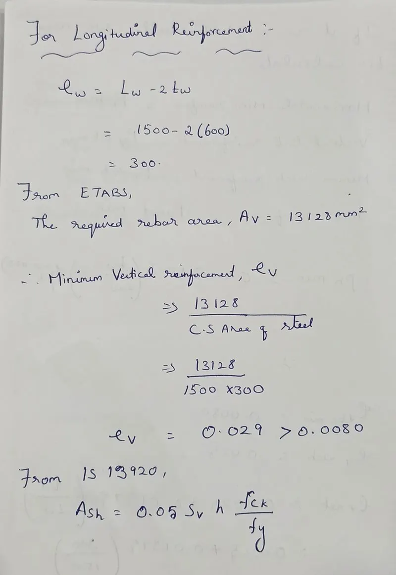
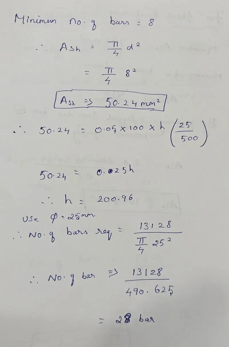
- Now for longitudinal reinforcement:
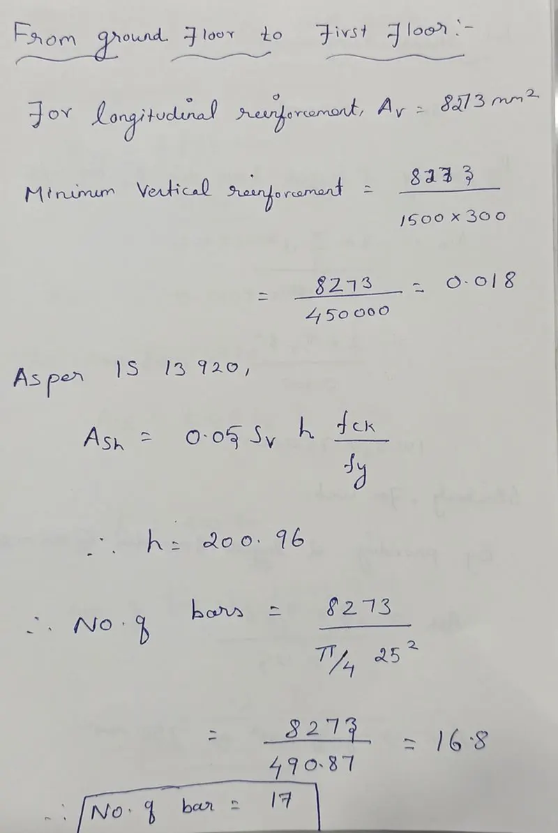
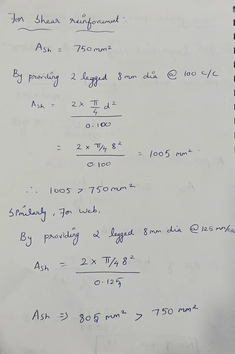
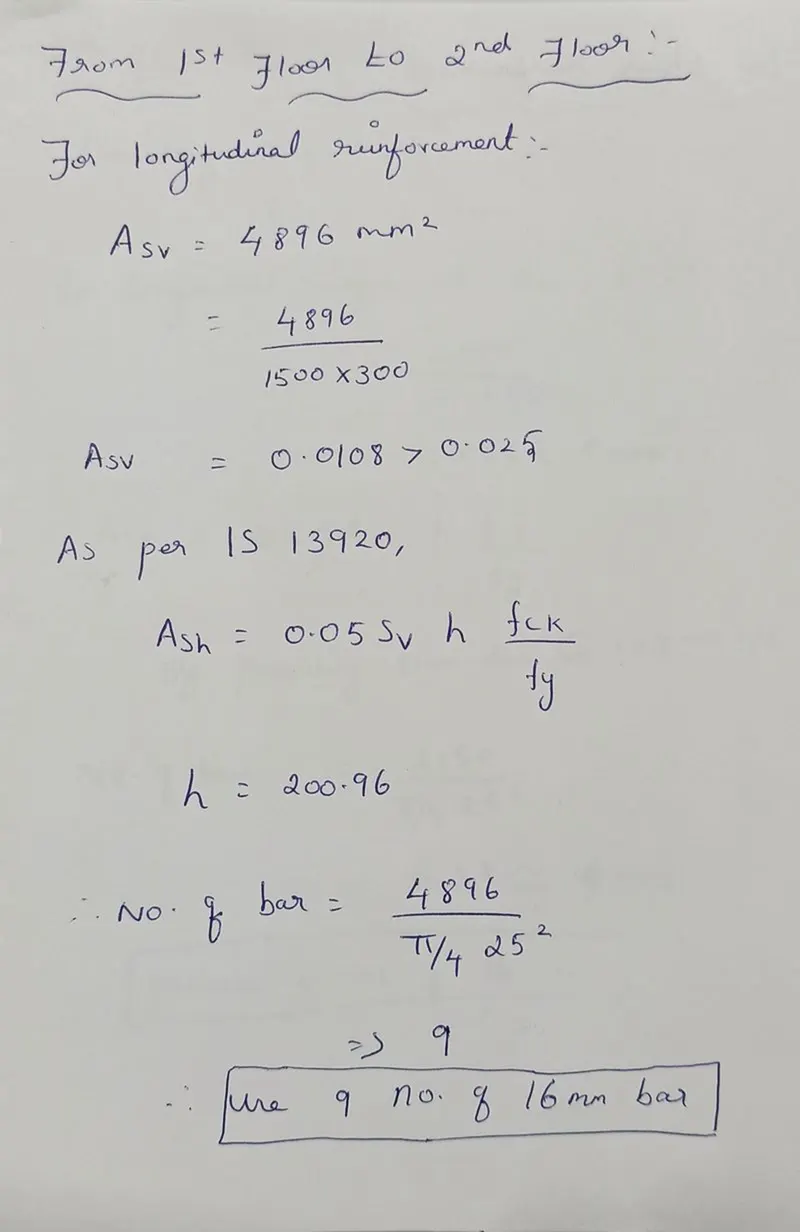
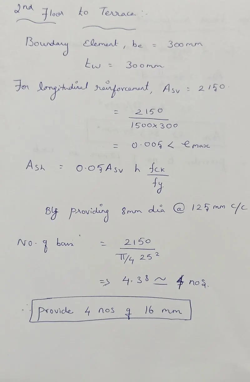
- Now we draft the reinforcement details in autocad using the obtained values.
Drawings: