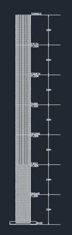
Analysis & Design of RCC shear walls in the model using ETABS
ANALYSIS & DESIGN OF RCC SHEAR WALLS IN THE MODEL USING ETABS
QUESTION:
The ETABS file for a G+6 building is provided. Run the analysis and design the RCC shear walls (show in the ETABS model). The following challenge deals specifically with the shear wall of size 300x1500 at grid A-11 in the structural model.
- Extract values of longitudinal steel ratio, boundary element length and shear reinforcing ratio from the design results.
- Provide cross sectional steel arrangement of the shear wall from its base up to terrace, in compliance with provisions of IS13920-2016. AutoCAD application can be used for this exercise. Alternatively, it can be drawn by hand as well.
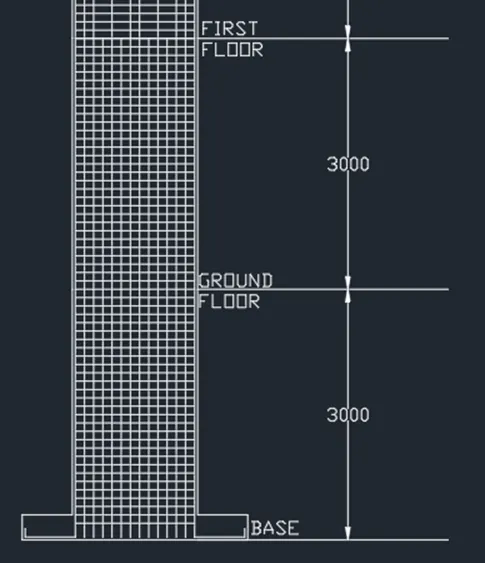
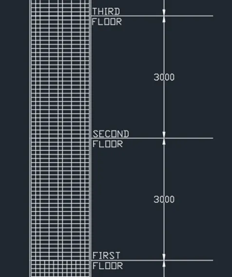
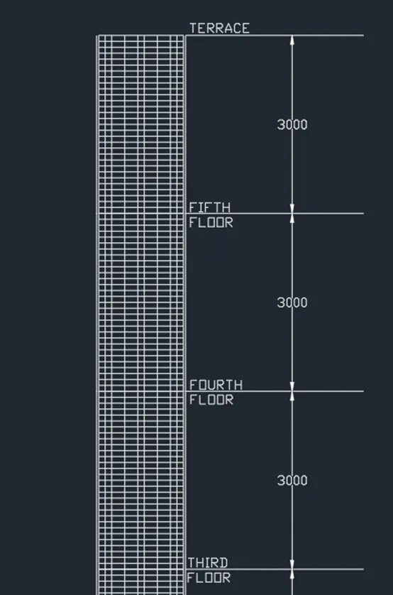
- Provide elevation drawings of the reinforcement details of the shear wall from base up to terrace.
ANSWER:
COMPLETE STEPWISE PROCEDURE FOR THE ANALYSIS AND DESIGN OF SHEAR WALLS USING ETABS
Open up the model for which you want to design the shear wall:
- As we all know, the very first step is to locate the file on your computer and open the ETABS model.
- And in our case, the file has been attached to the question.
- So, download the file, save it at an appropriate location within your system and then open the same using ETABS.
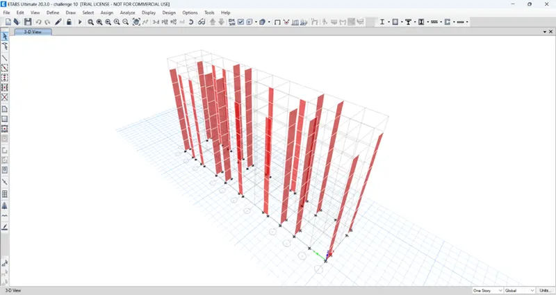
Check the model and run the analysis:
- Now that we have opened up the required model, we need to run the analysis using the software.
- However, before running the analysis, we need to first check the model for any structural defects.
- And to do that, simply drop down the analysis menu and click on the check option.
- Select all the options given in the menu and then run the check.
- Once the model has been checked and is free from errors, we can safely run the analysis.
- And to run the analysis, simply press the F5 key on your keyboard or click on the play button available on the ETABS screen.
Adjust the view settings:
- As we all know that ETABS is an extensive 3D modelling tool that generates results regarding any structural model.
- Therefore, we need to be able to filter the results according to what is needed from us at the moment.
- And this is where adjusting the view settings comes into play.
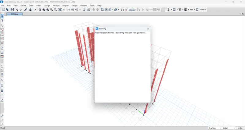
- Ans as we are expected to analyse and design the shear wall at the grid position A11.
- So, select the required shear wall and then right-click anywhere on the screen randomly.
- Then, click on the option called show selected objects only.
- This way, only the shear wall we need to design is going to be visible on your ETABS screen which will make the design a lot easier.
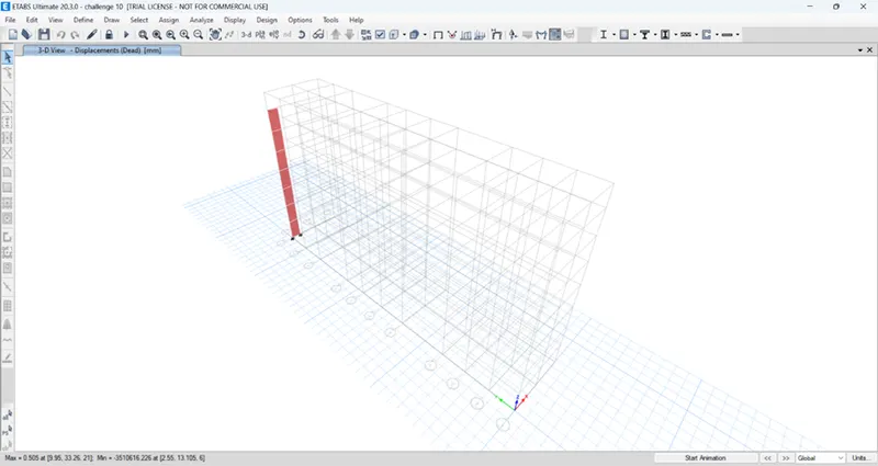
View/revise reference and run the shear wall design from the design menu:
- As we have already run the analysis and we have also filtered out the required shear wall within the model, we are set to run the shear wall design in ETABS.
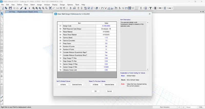
- However, before running the design, you need to make sure that the right codes are applied while running the automated design.
- And to do that, simply drop down the shear wall design menu and click on the view Revise references option.
- A dialogue box will appear where you can check or replace the design codes applicable while running the design.
- so, make sure your desired codes are selected based on your country/region where the project is located.
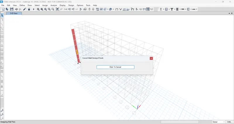
- After making sure the right codes are selected, now you can run the design by clicking on the shear wall design option available which is also inserted below for the references.
Gather the needed design data:
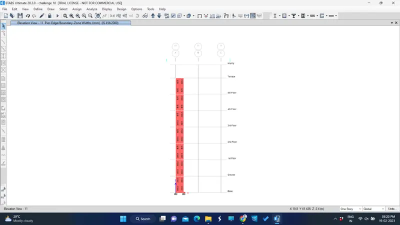
- Now after finishing the design process in the software, we need to collect the required reinforcement detailing data in order to go ahead with the detailing process.
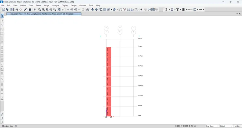
- So, primarily for shear walls, we need three main data for a safe detailing that are longitudinal reinforcement, shear reinforcement and the boundary element width.
- All of this can be displayed in ETABS by using the option called display design info within the shear wall design dropdown.
- Thus, all the required information was gathered and the same is inserted below for reference.
Maximum longitudinal reinforcement at the base:
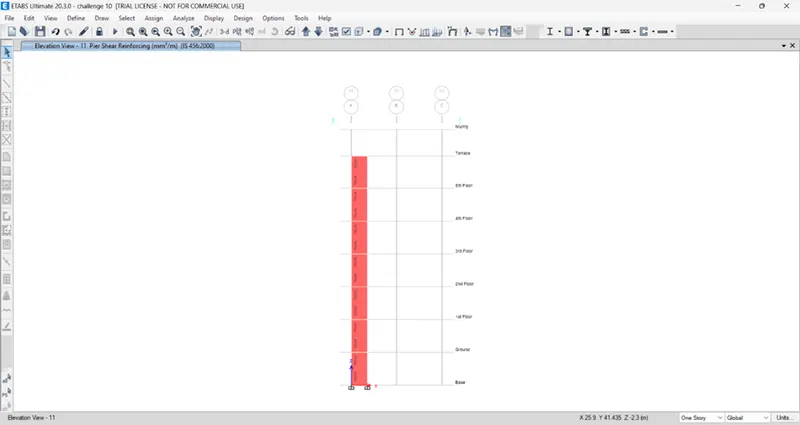
Consistent shear demand throughout the wall height:
Boundary width data:
Design summary:
Flexural information:

Shear info:

Boundary width info:
Conduct the design calculations in accordance with the IS13920 and execute the ductile detailing of shear wall using AutoCAD:
- The next step is to go ahead and place the reinforcement bars in the shear wall with proper calculations as per the clauses mentioned in the IS13920 codebook.
- So, the exact procedure for ductile detailing of reinforcement bars in the shear wall is explained below and thus the wall design is completed by preparing the good for construction drawings that can be sent to the site.
Section classification:
The first thing we need to check before proceeding with the detailing is if the geometrical properties of our wall are within the limits of IS13920 or not.
Thickness:
As per clause 10.1.2, the minimum allowable shear wall thickness is 150 mm or more. And in our case, we have a 300 mm thick shear wall. Our section is safe.
Length to thickness ratio:
As per clause 10.1.3, the minimum allowable length to thickness ratio must be greater than or equal to 4.
So, in our case, we have 1500 mm as the length and 300 mm thickness. Therefore 1500/3000 = 5>4. Hence ok.
Shear wall type:
As per clause 10.1.4, there are primarily three types of shear walls based on their geometrical properties. And the minimum reinforcement requirement also differs for these three tyeps.
- Squat walls: if hw/lw < 1
- Intermediate walls: if 1 < hw/lw < 2
- Slender walls: if hw/lw > 2
So for our case, hw/lw = 2100/1500 = 14>2
Hence ok.
Reinforcement layers:
As per clause 10.1.7, reinforcement shall be provided along with both faces of the wall if the wall thickness exceeds 200 mm.
So, as we have a 300 mm thick shear wall, we have to lay down the rebars along with both the faces of the wall.
Largest diameter of the rebar:
As per clause 10.1.8, the largest diameter of the longitudinal bar of the shear wall shall not exceed 1/10th of its thickness.
So, 1/10 x 300 = 30 mm.
Therefore, we can’t use any bar exceeding the 30 mm dia. Thus, we have to use the 25 mm dia as the largest bar for our project.
Ductile detailing calculations:
Following are the steps to be carried out while calculating the ductile detailing of reinforcement bars for shear walls from the ETABS output.
Section division:
As we all know that the entire five-floor shear wall can’t be detailed in one go. We must dive the wall along its height based on the reinforcement demand on each floor.
So, following the ETABS output, we have grouped the wall into two sections. The first section runs from the base until the first floor and the second one follows up till the terrace level.
Boundary element allocation:
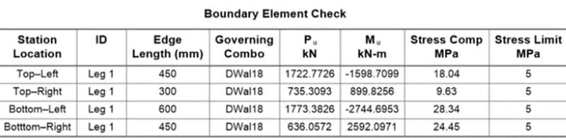
Based on the software output, the boundary width requirement at the base is 600 mm.
So, it is only viable to design the entire length for section 1 as the boundary element. Because we only have 300 mm as the web width which is very less. Hence for section 1 from the base to the first floor, we have to design the entire wall as the boundary element confining the rebars as per the IS13920.
But as we go to the upper floors, the boundary element demand reduces to 300 mm. so, we can adapt the boundary element of 300 mm on either side of the wall for section 2 running from the first floor to the terrace level.
Detailing from base to the first floor (section 1):
Shear demand:
As already obtained, we have a consistent shear demand of 750 sq.mm per 1000 mm height.
So, provide 8 mm dia shear links.
No. of bars = Ast/Ash = 750/100 = 7.5 = 8 bars.
Spacing = h/no. of bars = 1000/8 = 125 mm
Therefore, provide 8 mm dia shear links @ 125 mm c/c as the shear reinforcement for the entire wall.
However, the vertical spacing for shear links within the boundary element shall be governed by clause 10.4.4 which states that it should be 100 mm.
Longitudinal rebar demand (entire length is to be designed as the boundary element):
Required longitudinal reinforcement ratio = 0.0292
Ag = 1500x300 = 450000 sq.mm
Therefore,
Asc = 0.0292x450000 = 13140 sp.mm
Also,
Ash = 0.05 Sv h fck/fy
As we have used 8 mm dia stirrups @ 125 mm c/c, Ash = 50 sq.mm
Sv = 100 mm for boundary element As per clause 10.4.4
Fck = 25
Fy = 500
Therefore, h = 200 mm. meaning we cannot provide more than 200 mm spacing of longitudinal bars in the boundary element which is the entire length of the wall till the first floor.
So, minimum no. of bars = 1500-40/200 = 8 bars
Now, to cover the demand of 13140 sq.mm,
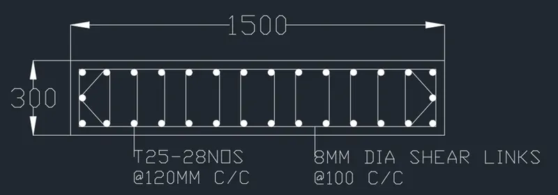
Provide 28 numbers of T25 bars.
Therefore, Ast provided = 490x28 = 13720 > 13140. Hence ok.
Also the spacing = 120 mm < 200 mm required. Hence ok.
So, provide 13 bars on one face making 26 on both sides. Also, provide 2 bars along the shorter span reducing the c/c spacing to 150 mm. hence ok.
The detailed GFC drawing for the above calculations is inserted below:
Reinforcement detailing from the base upto the first floor:
Detailing from the first floor till the terrace level (section 2):
- Design of the web steel:
web width = 900 mm
minimum reinforcement ratio for the web as per IS13920 = 0.0025
adopting 0.0030 for the safer calculations.
Ag = 900x300 = 270000
Asc = 0.0030x270000 = 810 sq.mm
Provide 6 numbers of T16 bars = 6x201 = 1206 > 210. Hence ok.
- Design of boundary element:
Minimum reinforcement ratio as per the code = 0.008
Boundary width = 300 mm
Ash = 0.05 Sv h fck/fy
As we have used 8 mm dia stirrups @ 125 mm c/c, Ash = 50 sq.mm
Sv = 100 mm for boundary element as per clause 10.4.4
Fck = 25
Fy = 500
Therefore, h = 200 mm
Reinforcement required = total Ast – Ast taken by the web = 4896-810 = 4086 sq.mm
Now, there are two boundary elements. So, Ast required for one BE = 4086/2 = 2043 sq.mm
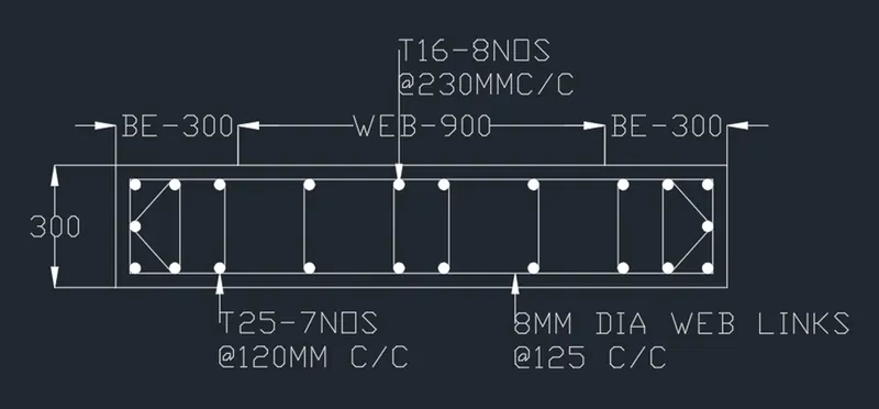
Thus, provide 7 numbers of T25 bars
Ast provided = 7x490 = 2940 > 2043. Hence ok.
Reinforcement ratio check:
Ratio = Ast/bw x tw = 2940/300x300 = 0.032 > 0.008. hence ok.
NOTE: we have carried 14 T25 bars from the floor below satisfying the 50% lapping condition at one go.
The detailed drawing of the above calculations is as follows:
Reinforcement detailing from the third floor upto the terrace level:
Elevation drawing of the shear wall:
- From base till first floor:
- From first floor till third floor:
- From third floor till terrace level:
Final output: