Analysis & Design of RCC shear walls in the model using ETABS
AIM:
The etabs file for a G+6 building is provided. Run the analysis and design the RCC shear walls (show in the etabs model). The following challenge deals specifically with the shear wall of size 300x1500 at grid A-11 in the structural model.
- Extract values of longitudinal steel ratio, boundary element length and shear reinforcing ratio from the design results.
- Provide cross sectional steel arrangement of the shear wall from its base up to terrace, in compliance with provisions of IS 13920 – 2016. AutoCAD application can be used for this exercise. Alternatively, it can be drawn by hand as well.
- Provide elevation drawings of the reinforcement details of the shear wall from base up to terrace.
INTRODUCTION:
In structural engineering, a shear wall is a vertical element of a system that is designed to resist in-plane lateral forces, typically wind and seismic loads. In many jurisdictions, the International Building Code and International Residential Code govern the design of shear walls.
A shear wall resists loads parallel to the plane of the wall. Collectors, also known as drag members, transfer the diaphragm shear to shear walls and other vertical elements of the seismic force resisting system. Shear walls are typically light-framed or braced wooden walls with shear panels, reinforced concrete walls, reinforced masonry walls, or steel plates.
PROCEDURE:
Open the attached file
Run analysis
Click the concrete frame design
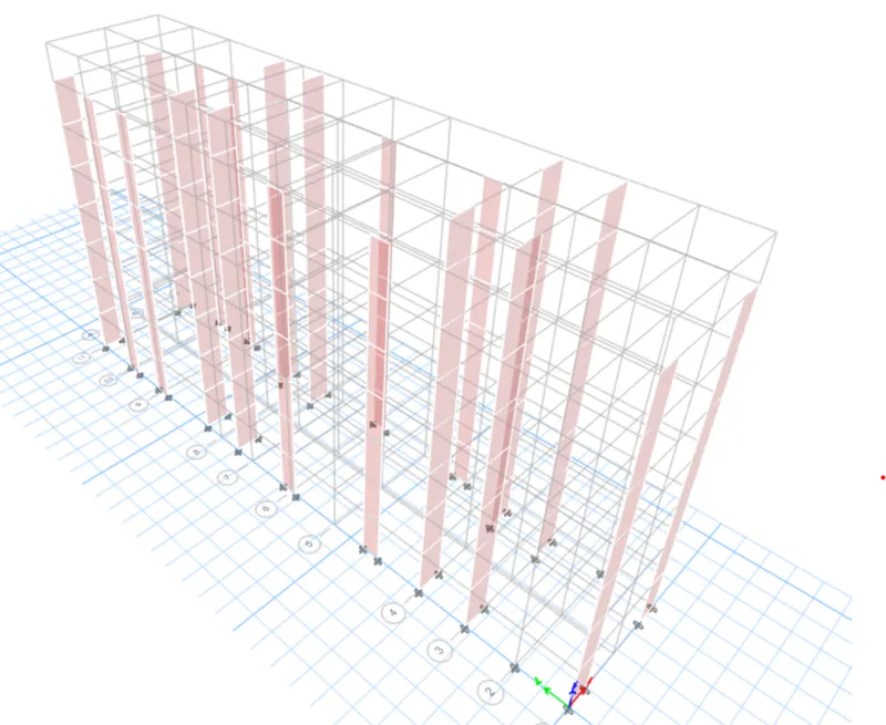
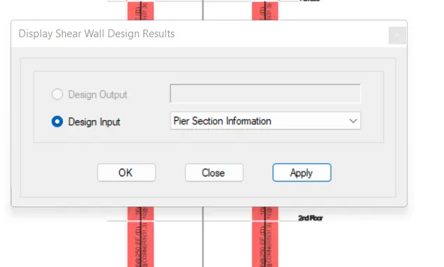
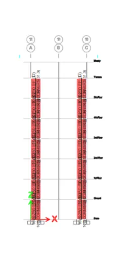
Click display design info & choose pier section information under shear reinforcement tool
Check the failures
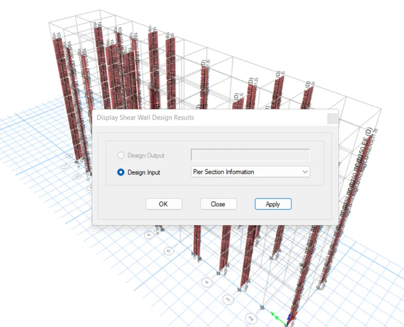
Click on the wall ,click the details & check any failures occurs
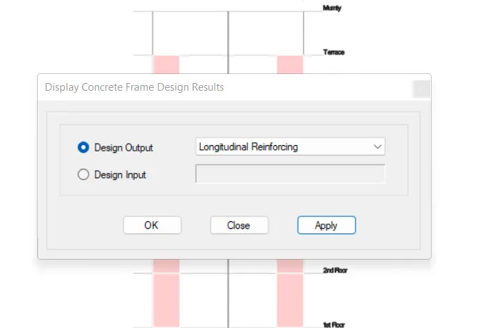
Go to concrete frame design>display design info>longitudnal reinforcement
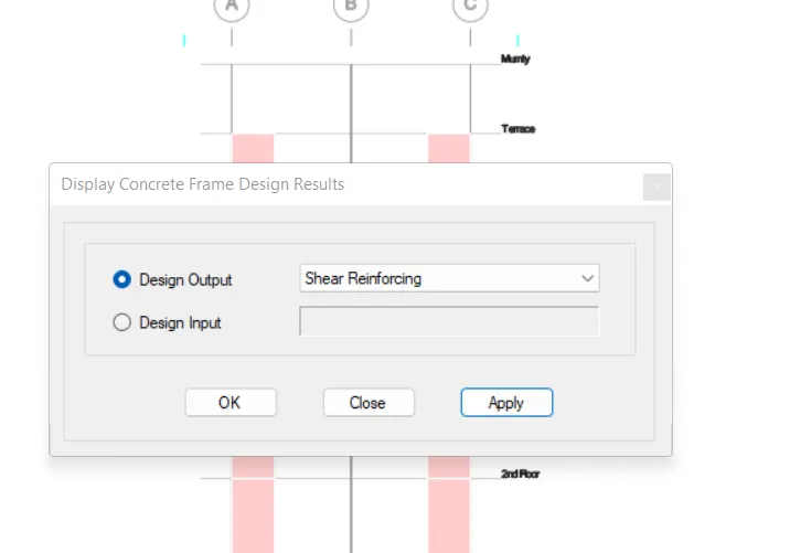
Click concrete frame design>display design info >shear reinforcing
Under shear wall design click design info choose pier information
Calculation:
As per 13920-2016
a)Classification of shear wall as per IS 13920-2016
Total height of the wall h=21000 & length of the wall 1500
h/L =14>2
The given wall is slender
b) minimum net vertical reinforcement as per IS 13920 – 2016 table 1
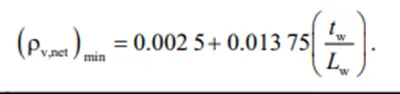
= 0.0025 + 0.01375 (300/1500)
= 0.00525 of wall cross section
= 0.00525 x 1500 x 300 = 2362 mm2
c) minimum horizontal reinforcement as per IS 13920 – 2016 table 1
= 0.0025 + 0.5 (21/15 – 2) x 0
= 0.0025 which is the same 750mm2/m
d) minimum vertical reinforcement in boundary limit
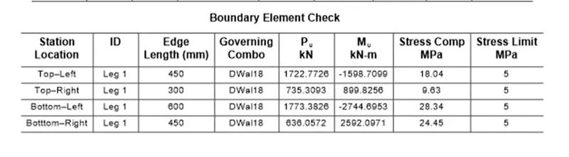
left 600mm width boundary element = 1440 mm2
right 450mm width boundary element = 1080 mm2
e): confining reinforcement spacing for the boundary element as per IS 13920 – 2016
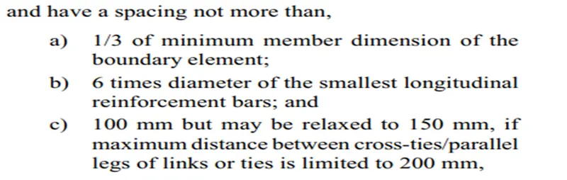
1/3 minimum rebar member dimension = 300/3 = 100mm
6 time smallest main bar 6x25 = 150mm
Max reinforcement of confining reinforcement in boundary element are 150mm
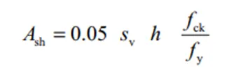
Sv = 150mm , h = 1000mm
Ash = 452mm2
RESULT:
Sv = 150mm , h = 1000mm
Ash = 452mm2