Air Standard Cycle : Otto Cycle
AIM : To write a MATLAB program to solve an otto cycle and plot a Pressure-Volume diagram.
OBJECTIVE :
- Create a program using MATLAB to plot a Pressure-Volume diagram of an otto cycle.
- To calculate the thermal efficiency of an otto cycle.
THEORY :
Air Standard Cycle(Otto cycle) :
The Otto Cycle, describes how heat engines turn gasoline into motion. Like other thermodynamic cycle, this cycle turns chemical energy into thermal energy and then into motion. The Otto cycle describes how internal combustions engines (that use gasoline) work, like automobiles and lawn mowers.
The following assumptions are made for the air standard cycle:
- The working fluid (air) has a constant mass throughout the entire air cycle and air is
taken to be ideal. - The air maintains a constant specific heat capacity throughout the cycle.
- The combustion process is replaced by a heat transfer process from an external heat
source. - The cycle is completed by the heat transfer to the surrounding in contrast to the
exhaust and the intake processes of an actual engine. - All the processes are internally reversible.
Working of an otto cycle :
In 1876, Nikolaus August Otto (German Engineer) proposed this Air Standard Cycle. This is the idealized cycle for the spark-ignition engine.
In spark ignition internal engine, there are four operations in the thermodynamic cycles. They are,
- Suction or intake stroke,
- Compression stroke,
- Expansion or power stroke,
- Exhaust stroke
All these four processes are explained with the help of a P-V diagram in the Otto Cycle.
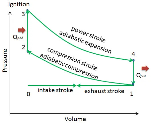
Process 0-1 and 1-0 :
When the engine is working on the full throttle, the Process 0 → 1 and 1 → 0 represents the suction and the exhaust process of Thermodynamic cycle in the P-V diagram and the effect of these two processes considered as nullified.
Process 1 to 2 :
The process 1 → 2 is the isotropic compression of the air in the cylinder while piston moves from the bottom dead centre (BDC) to the top dead centre (TDC).
Process 2 to 3 :
During the process, 2 → 3 the heat is supplied at a constant volume. This is the spark ignition and the combustion of the air-fuel mixture is takes place in the cylinder during this process 2 → 3.
Process 3 to 4 and 4 to 1 :
These two processes 3 → 4 & 4 → 1 will represent the isotropic expansion (Piston moves from the Top dead centre to the bottom dead centre) and the constant volume heat rejection respectively.
GOVERNING EQUATIONS :
I. Swept Volume(`V_s`) : Volume swept by the piston during its motion is called swept volume.
It is given by,
`V_s = pi/4d^2l` Where,
d = bore of the piston,
l = length of the piston/stroke
II. Clearance Volume(`V_c`) : The volume which is left between the piston and top death center of the cylinder during the exhaust stroke is called as clearance volume.
It is given by,
`V_c = V_s/(r_c-1)` Where,
`r_c` = compression ratio of the cylinder
III. Adiabatic process : Adiabatic process in thermodynamics, change occurring within a system as a result of transfer of energy to or from the system in the form of work only; i.e., no heat is transferred.
It is given by,
`PV^gamma` = constant Where,
P = Pressure of the system,
V = Volume of the system,
`gamma` = ratio of the specific heats
IV. Change of volume inside the engine combustion chamber :
It is given by,
`V/V_c = 1 + 1/2(r_c-1)[R+1-costheta-(R^2-sin^2theta)^(1/2)]`
Where,
V = Volume inside cylinder when piston is at an angle `theta`
`V_c`= Clearance volume
`r_c` = compression ratio of the cylinder
R = Ratio of length of connecting rod to, crank pin radius
`theta` = angle of piston
V. Thermal efficiency of an otto cycle :
It is given by,
`eta = 1-1/(r_c)^(gamma-1)`
Where,
`eta` = Thermal efficiency,
`r_c` = compression ratio,
`gamma` = ratio of the specific heats
MATLAB CODE :
- First a function is need to declares where we will define the otto engine kinematics.
- This function [V] was named as otto_engine_kinematics.
- This function helps in creating the those curves by relating pressure and volume.
Program 1 :
function [V] = otto_engine_kinematics(bore,stroke,con_rod,cr,start_crank,end_crank)

V_swept = (pi/4)*bore^2*stroke;
V_clear = V_swept/(cr-1);
a = stroke/2;     % crank pin in metre
R = con_rod/a;    % ratio of conecting rod to crank pin

% A linearly spaced vector of theta is created to store the array

theta = linspace(start_crank,end_crank,200);

term1 = 0.5*(cr-1);
term2 = R + 1 - cosd(theta);
term3 = (R^2 - sind(theta).^2).^0.5;

V = (1 + term1*(term2 - term3)).*V_clear;    % volume at angle theta
end
So we need a program to call this function[V] to determine the state variables at the end of each process.
Program 2 :
% A program to plot PV diagram and calculate efficiency of an otto cycle.
clear all
close all
clc

% Inputs

gamma = 1.4;

% Engine geometric parameters

bore = 0.05;             % Diameter of the cylinder in metre
stroke = 0.075;          % Length of the piston movement in metre
con_rod = 0.15;
cr = 9;                  % Compression ratio

% calculating the swept volune and clearance volume

V_swept = (pi/4)*bore^2*stroke;
V_clear = V_swept/(cr-1);

% state variables at point 1
V1 = V_swept+V_clear;            % Volume in cubic metre
P1 = 105890;                     % Pressure in Pascal
T1 = 300;                        % Temperature in kelvin

% state variables at point 2

V2 = V_clear;
P2 = P1*cr^(gamma);              % using adiabatic equation P1V1^gamma = P2V2^gamma
                                 % P2 = P1*(V1/V2)^gamma
                                 % cr = (V1/V2); P2 = P1*cr^gamma
T2 = (P2*V2*T1)/(P1*V1);         % Using Gas Law (P1V1)/T1 = (P2V2)/T2
                                 % T2 = (P2*V2*T1)/(P1*V1)

% creating volume and pressure array for compression process

constant_c = P1*V1^gamma;
V_compression = otto_engine_kinematics(bore,stroke,con_rod,cr,180,0);
P_compression = constant_c./V_compression.^gamma;

% state variable at point 3

T3 = 1990;
V3 = V2;
P3 = (P2*T3)/(T2);                % Using Gas Law (P3V3)/T3 = (P2V2)/T2
                                  % P3 = (P2*T3)/(T2)

% creating volume and pressure array for expansion process

constant_c = P3*V3^gamma;
V_expansion = otto_engine_kinematics(bore,stroke,con_rod,cr,0,180);
P_expansion = constant_c./V_expansion.^gamma;

% state variable at point 4

V4 = V1;
P4 = P3*(V3/V4)^(gamma);              % using adiabatic equation P3V3^gamma = P4V4^gamma
                                      % P4 = P3*(V3/V4)^(gamma)
T4 = (P4*V4*T3)/(P3*V3);              % Using Gas Law (P3V3)/T3 = (P4V4)/T4
                                      % T4 = (P4*V4*T3)/(P3*V3)

% Calculating the thermal efficiency of otto cycle

thermal_efficiency = 1-((cr)^(1-gamma))
effeciency_in_per = thermal_efficiency*100

figure(1)

hold on
grid on
colour = [rand rand rand];  % use for random colour for plot

plot(V1,P1,'*','color','r')
plot(V_compression,P_compression,'LineWidth',1.75)
plot(V2,P2,'*','color','g')
plot([V2 V3],[P2 P3],'color',colour,'LineWidth',1.75)
plot(V3,P3,'*','color','b')
plot(V_expansion,P_expansion,'LineWidth',1.75)
plot(V4,P4,'*','color','k')
plot([V4 V1],[P4 P1],'color',colour,'LineWidth',1.75)
title("Air Standard Cycle : Otto Cycle")
legend("Initial state","Isentropic compression","Before heat addition","Isochoric heat addition","After heat addition","Isentropic expansion","Heat rejection start","Isochoric heat rejection")
xlabel("Volume in (cubic meters)")
ylabel("Pressure in Pascal")
Step wise explanation of the code :
1. The code starts with the command clear all, close all and clc. Where,
- clear all : it is used to clear the data stored in workspace.
- close all : it is used to close all the plots abd figure.
- clc : it is used to clear the command window.
2. Now, inputs the known geometric parameters of engine, such as bore, stroke, compression ratio and length of connecting rod.
3. After initialise of engine geometrc parameters, Calculation of swept volume and clearance volume is done by the given equation and strored in variable V_swept and V_clear respectively.
4. Input the states variable of point 1 such Pressure, Volume and Temperature and stored the value in `P_1`,`V_1` and `T_1` respectively.
- V1 is calculated by equation `V_1` = V_swept and V_clear.
5. Calculation of the states variable of point 2 such Pressure, Volume and Temperature and stored the value in `P_2,V_2 and T_2` respectively.
- Volume at point 2 is the volume of compression so `V_2 =`V_clear.
- Calculation of Pressure at point 2, by using adiabatic equation `P_1V_1^gamma = P_2V_2^gamma`.
- Calculation of Temperature at point 2, by using Using Gas Law `(P_1V_1)/T_1 = (P_2V_2)/T_2`.
6. Creating volume and pressure array for compression process of an otto engine,
- First store the value of `P_1V_1^gamma` in constant_c.
Now the volume and pressure array is given by,
- V_compression = otto_engine_kinematics(bore,stroke,con_rod,cr,180,0)
- P_compression = constant_c./V_compression.^gamma.
7. Calculation of the states variable of point 3 such Pressure, Volume and Temperature and stored the value in `P_3,V_3 and T_3` respectively.
- As the process is constant volume heat addition so, Volume at state point 2 and point 3 is same.
- Calculation of Pressure at point 3, by using Gas Law `(P_2V_2)/T_2 = (P_3V_3)/T_3`
- Temperature at point 3 is given as `T_3 = 1990`.
8. Creating volume and pressure array for expansion process
- First store the value of `P_3V_3^gamma` in constant_c`.
Now the volume and pressure array is given by,
- V_expansion = otto_engine_kinematics(bore,stroke,con_rod,cr,0,180)
- P_expansion = constant_c./V_expansion.^gamma.
9. Calculation of the states variable of point 4 such Pressure, Volume and Temperature and stored the value in `P_4,V_4 and T_4` respectively`.
- As the process is constant volume heat addition so, Volume at state point 4 and point 1 is same.
- Calculation of Pressure at point 4, by using adiabatic equation `P_3V_3^gamma = P_4V_4^gamma`.
- Calculation of Temperature at point 4, by using Using Gas Law `(P_3V_3)/T_3 = (P_4V_4)/T_4`.
10. Calculating the thermal efficiency of an otto cycle by equation, thermal_efficiency = `1 - (1)/r_c^((gamma-1))`.
11. Now the figure command is initiated which simply opens a separate blank window where new graphs are about to be plotted.
12. Creating a variable name colour to store random color for plotting the graph.
13. Plot command is used to plot all the points with colors and linewidth of 1.75.
14. Call the legend command that creates a legend with descriptive labels for each plotted data series.
15. Now label x-axis and y-axis as Volume and Pressure using xlabel and ylabel command respectively.
ERROR FACED WHILE PROGRAMMING :
- The colour variable is not declared.
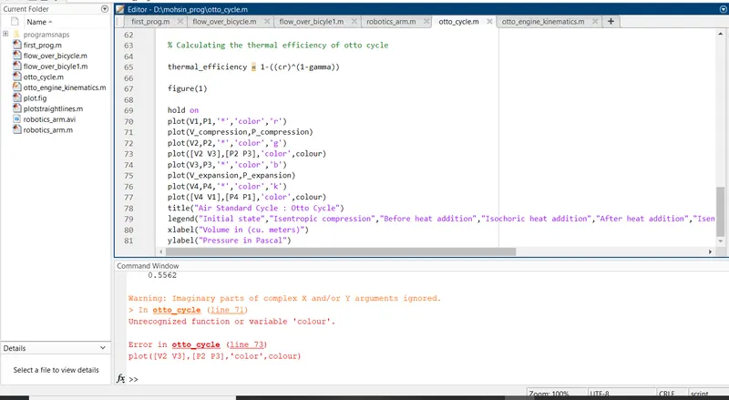
It was fixed by initiate the colour variable in random command for plot the diagram in random color.
- Element wise operator was missing while using arithmatic operation on arrays.
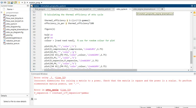
To perform element wise matrix. Use "." at required place.
RESULT :
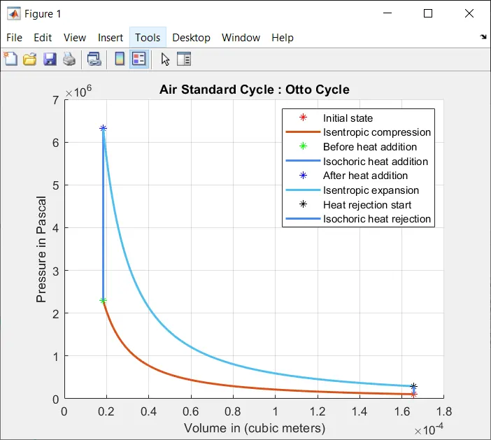
- The P-V diagram of an otto cycle is plotted.
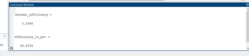
- Thermal efficiency of an otto cycle is calculated as :
thermal efficiency = 58.48%.
CONCLUSION :
Air standard effieciency depends on the compression ratio, for high compression ratio efficiency is high.
Higher compression ratios will however make gasoline engines subject to engine knocking, caused by autoignition an unburned mixture, if lower octane-rated fuel is used. The unburned mixture may autoignite by detonating from pressure and heat alone, rather than ignite from the spark plug at exactly the right time.
The engine knocking can be reduced by using high-octane fuel, which increases the gasoline’s resistance to autoignition. The higher the octane number, the more compression the fuel can withstand before detonating (igniting). Since the temperature attained by the fuel-air mixture during the compression increases as the compression ratio increases, the likelihood of autoignition increases with the compression ratio.
The autoignition can reduce efficiency or damage the engine if knock sensors are not present to modify the ignition timing.