Air standard cycle
AIM :- To visualize P-V Diagram of Otto Cycle and to calculate thermal efficiency using Matlab.
OBJECTIVE:-
- To study the Otto Cycle and write a program to calculate the state variables of Otto Cycle.
- To write a program to plot a P-V diagram of the Otto Cycle.
- To calculate Thermal Efficiency of Otto Cycle using Matlab.
THEORY :
Air Standard Cycle –
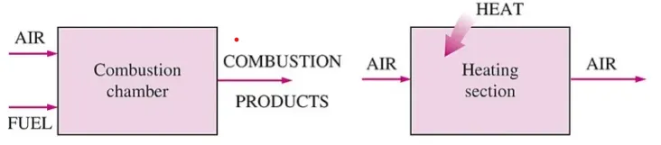
To carry out the analysis of the heat engines, the concept of air standard cycles was conceived. In these cycles certain mass of air is considered to be working in the thermodynamic cycle. The addition and rejection of heat is considered to take place with the external reservoir and ideally all the processes are reversible. The internal combustion engines are considered to be working on the principle of air standard cycles. The two most commonly used air standard cycles are Otto cycle and Diesel cycle. The Otto cycle corresponds to four stroke gasoline or petrol engines also called Spark Ignition (SI) engines. The Diesel cycle corresponds to four stroke Diesel engines also called as Compression Ignition (CI) engines.
Assumptions made in Air Standard Cycles -
- Air continuously circulates in a closed loop.
- Always behaves as an ideal gas.
- All the processes that make up the cycle are internally reversible.
- The combustion process is replaced by a heat-addition process from an external source.
Otto cycle:-
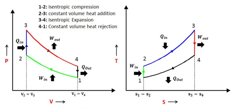
The Otto cycle is an air standard cycle which approximates the processes in petrol or diesel engines. It is based on constant volume heat addition (combustion) and heat rejection processes, and isentropic compression and expansion. The air-standard Otto cycle is the idealized cycle for spark-ignition internal combustion engines. This cycle is shown above on P–V and T-S diagrams. The spark-ignition engine is modelled with this Otto cycle. The actual P-V diagram for an engine has rounded corners because of the processes of combustion take place at a finite rate. The Ideal Otto cycle has sharp corners because the ‘combustion’ is switched on and off instantaneously.
The Otto cycle 1 → 2 → 3 → 4 consists of following four processes:
Process 1 → 2: Reversible adiabatic compression of air;
Process 2 → 3: Heat addition at constant volume;
Process 3 → 4: Reversible adiabatic expansion of air;
Process 4 → 1: Heat rejection at constant volume.
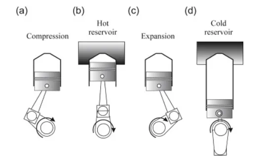
A typical engine cycle of four-stroke petrol engine is defined in the above figure. It consists of a compression stroke(a), followed by a period of combustion close to top dead centre(b) and then by expansion(c). These two strokes form the power producing processes, but afterwards the products of combustion have to be replaced by fresh air. So the exhaust valve is open at the beginning of the exhaust stroke and the burnt gases is expelled away by the upward motion of the piston(d). In a four-stroke engine the piston executes two complete revolutions of the crankshaft, and uses two strokes while the gas is pushed out by the piston on the up stroke, and then the intake valve is opened to enable air to be induced.
The explanation of above processes are as follows:-
Process 1-2: Reversible Adiabatic Compression or Isentropic Compression:
The air is compressed into the clearance volume of the cylinder and thus raising the pressure and temperature of the air. But, entropy remains constant as there is no heat transfer across the cylinder walls.
Heat is supplied to air from hot body while the volume of the air remains constant. Thus the work done is zero but the pressure and temperature of the air increase further to the maximum value attained in the cycle. Due to heat supply(addition), there is an increase in entropy.
Process 3-4: Reversible Adiabatic Expansion or Isentropic Expansion:
Air expands adiabatically causing the work-energy to be transferred to the surroundings at the expense of internal energy of the air.Entropy remains constant as there is no heat transfer but the Pressure, Temperature and Volume decreases from stage 3 to 4
Process 4-1: Constant Volume heat rejection or Heat Rejection:
Heat is rejected from air to cold body. During the heat rejection, the air is maintained at constant volume and due to heat rejection, entropy decreases, pressure and temperature also decrease to initial state.
GOVERNING EQUATIONS :
- Swept Volume(Vs)- The volume swept by the piston by travelling from one dead centre to another dead centre.It is denoted by Vs.
`Vs = pi/4timesd^2timesl`
where,
d = diameter or bore of the piston.
l = height of the piston
- Clearance Volume (Vc) – The space or volume which is left between the piston and top dead center of the cylinder during the combustion or exhaust stroke is called as clearance volume.
`Vc =frac{Vs}{(rc-1)}`
where,
rc = Compression Ratio of the cylinder.
- Total Volume (VT) – The Total Volume of the cylinder is the summation of Swept Volume of the piston and the Clearance Volume.
`VT=Vs+Vc`
-
Adiabatic Process- A thermodynamic system in which there is a change in the state of matter due to the change in the Pressure, Volume, Temperature (P, V, T) without transferring heat or mass with the thermodynamic system or its surroundings.The process in which the work done is in the form of a change in internal energy (U) and the amount of heat transferred, Q is zero (or there is no gain or loss of heat)
`PV^gamma=Constant`
where,
P = Pressure of the system;
V = Volume of the system;
g = Value of ratio of specific heats for the fluid.
- Combined gas law-The combined gas law relates pressure, temperature, and volume when everything else is held constant (mainly the moles of gas, n). The most common form of the equation for the combined gas law is as follows:
`frac{PV}{T}=Constant`
- Change of volume inside the engine combustion chamber is given by,
`frac{V}{Vc}=1+1/2(rc-1)[R+1-costheta-(R^2-sin^2theta)^frac{1}{2}]`
where,
V = Volume inside cylinder when piston is at an angle `theta`.
R = Ratio of length of connecting rod to crank pin radius (a).
Also crank pin radius (a) = stroke length `l/2`
- Thermal Efficiency of Otto Cycle (h) – It is given as,
`eta=1-(frac{1}{rc^((gamma-1))})`
APPLICATIONS OF OTTO CYCLE:-
The applications of Otto Cycle are as follows:-
- The Otto cycle was essential for the modern world where it can provide energy for most of the transportation.
- The variety of automobiles seen on the road which uses the Otto Cycle to convert gasoline into motion i.e. Chemical Energy--> Heat Energy-->Mechanical Energy.
MATLAB CODE:-
clear all
close all
clc

% Inputs
gamma = 1.4
t3 = 3000            %in Kelvin

% State variables
p1 = 101325          %in Pa
t1 = 500             %in Kelvin

%Engine geometric parameters
bore = 0.1;          %in metres
stroke = 0.1;        %in metres
con_rod = 0.15;      %in metres
cr = 14;             %in metres

% Caculating the swept volume and the clearance volume
v_swept = (pi/4)*bore^2*stroke;
v_clearance = v_swept/(cr-1);

v1 = v_swept + v_clearance
v2 = v_clearance

% State variable at state point 2
% p2v2^gamma = p1v1^gamma
% p2 = p1*(v1/v2)^gamma = p1*cr^gamma
p2 = p1*cr^gamma;

%p1v1/t1 = p2v2/t2 | t2 = p2*v2*t1/(p1*v1)
t2 = p2*v2*t1/(p1*v1);

constant_c = p1*v1^gamma;
V_compression = engine_kinematics(bore,stroke,con_rod,cr,180,0);

P_compression = constant_c./V_compression.^gamma;


% State variable at state point 3
v3 = v2

%p3v3/t3 = p2v2/t2 | p3 = p2*t3/t2
p3 = p2*t3/t2

constant_c = p3*v3^gamma;
V_expansion = engine_kinematics(bore,stroke,con_rod,cr,0,180);

P_expansion = constant_c./V_expansion.^gamma;


% State variable at state point 4
v4 = v1

%p3v3^gamma = p4v4^gamma | p4 = p3(v3/v4)^gamma
p4 = p3*(v3/v4)^gamma;

t4 = p4*v4*t3/(p3*v3);

%Thermal Efficiency
Thermal_Efficiency = 1-((cr)^(1-gamma))


figure(1)
hold on
plot(v1,p1,'*','color','r')
plot(V_compression,P_compression,'color','r')
plot(v2,p2,'*','color','r')
plot(v3,p3,'*','color','r')
plot(V_expansion,P_expansion,'color','g')
plot(v4,p4,'*','color','r')


plot([v1 v1],[p1 p4])
plot([v2 v2],[p2 p3])
xlabel('volume (m^3)')
ylabel('pressure (kpa)')
EXPLANATION OF CODE:-
clear all- clearing all variable in workspace
close all- for closing all figure windows
clc- for clearing command window
- Then the given inputs of `gamma`, t3, p1, t1, are entered. Here pn represents pressure at state point ‘n’, tn represents temperature at point ‘n’ and vn represents volume at point ‘n’ where ‘n’ can be 1, 2, 3 or 4.
- Then the Engine Geometric parameters are entered which include bore diameter, stroke length, connecting rod length and the compression ratio of the engine.
- The swept volume and clearance volume is calculated using some relations and formulas.
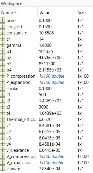
- The state variables v1, v2, p2, t2, v3, p3, v4 and p4 are calculated using the formulas.
- Now,seperate code is written in new script to get set of solution for every values of crank angle , a separate code is written in new script.
Function Code:-
function [V] = engine_kinematics(bore, stroke, con_rod, cr, start_crank, end_crank)


a = stroke/2;
R = con_rod/a;

v_s = pi/4*bore^2*stroke;
v_c = v_s/(cr-1);


theta = linspace(start_crank,end_crank,100);

term1 = 0.5*(cr-1);
term2 = R+1 - cosd(theta);
term3 = (R^2 - sind(theta).^2).^0.5;


V = (1 + term1*(term2 - term3)).*v_c;


end- Here,'function' syntax is used that accepts inputs “bore, stroke, con_rod, cr, start_crank, end_crank” and returns outputs in the “V” array.
- To figure this array the formulas or a, R, Vs and Vc are entered.
- The value of crank angle ‘theta’ is calculated for 100 values between initial angle and final angle.
- Then to obtain a curve, the equation of V i.e Volume inside cylinder when piston is at an angle `theta` is formulated.
- This function is called in the code and V_compression, P_compression, V_expansion, P_expansion is calculated with respect to the values of crank angle ‘theta’.
- The Thermal Efficiency is calculated by using the formula .
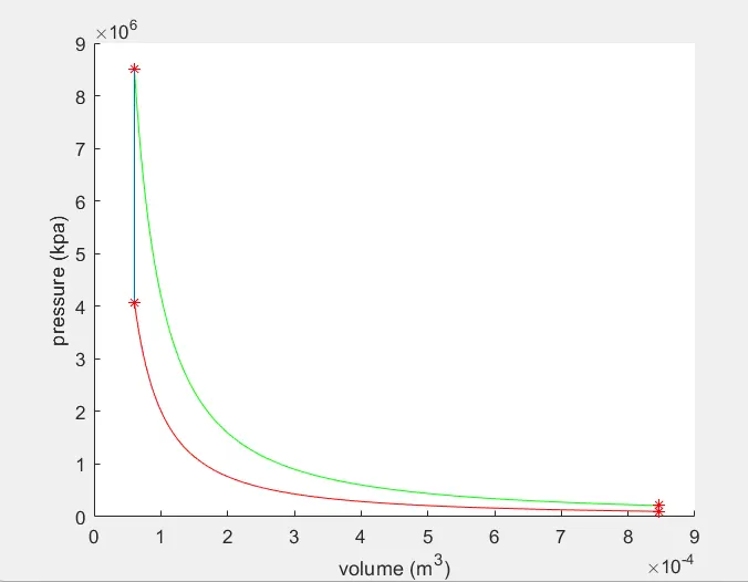
- Finally all state variable points are plotted along with the curves and the PV cycle is thus obtained.
OUTPUTS:-
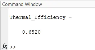
Thermal Efficiency-
PLOT FOR P-V DIAGRAM:-
VALUES FROM WORKSPACE:-
RESULTS:-
- The P-V diagram for all the four process have been plotted. It is been noted that the actual P-V diagram has round corners compared to ideal P-V diagram.
- The thermal efficiency of the Otto Cycle is 65.20%. As noted, the thermal efficiency mainly depends on compression ratio of the engine and the type of fluid. So it can be concluded that engines with higher compression ratio will have high thermal efficiency.