Simulation of flow over an Ahmed Body using Ansys Fluent
Aim:
To simulate the flow of air around the Ahmed body using Ansys fluent and compare them with the standard results and draw conclusions.
Theory:
The Ahmed body is a simplified car vehicle model. The exact solution for this model is already predetermined. This model is used to validate any now CFD code which is used to which is written for external aerodynamic simulations. The validation is done by comparing the results obtained by running simulations form the developed code to the standard results.
Solution:
1. Dimensions
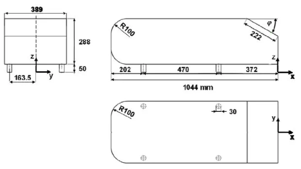
The Ahmed body is a simplified car vehicle model. This geometry resembles the shape of a car. The dimensions of this model are given as follows:
2. Modeling:
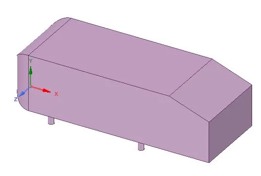
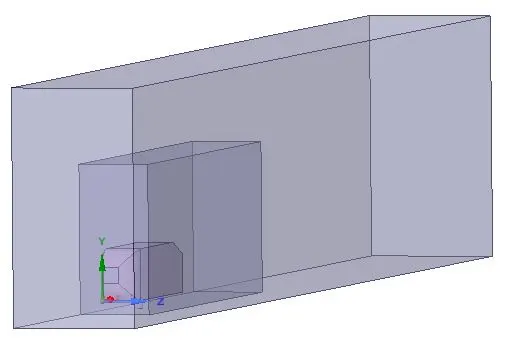
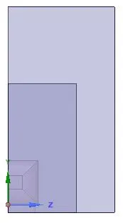
Since the Ahmed body is symmetric about the XY plane, the geometry is divided along this plane to simplify the problem. By doing so, the number of mesh elements, and hence the computation time reduces considerably. By using this model, even more number of mesh elements be added in the region of interest, which increases the accuracy of the solution. Keeping this in mind, two enclosures are defined around the simplified model as shown below. This allows us to provide smaller mesh elements near the simplified model which helps us understand the flow properties near the model. Larger mesh elements can be provided to the larger enclosure.

3. Meshing
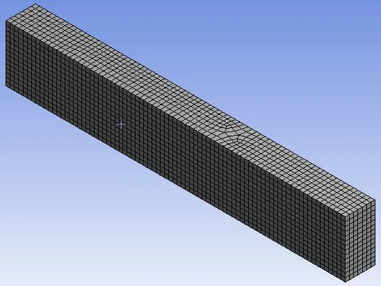
Once the geometry is modeled in SpaceClaim, the discretization of this model takes place in Fluent. Here, the bigger enclosure is provided with the multizone mesh of element size 0.1m. The smaller enclosure is provided with a tetrahedral mesh of element size 0.05m.

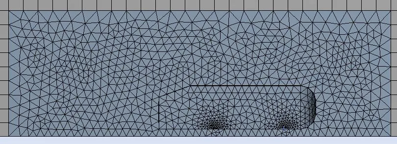
To obtain a smooth circular profile near the circular walls of the Ahmed body, the face sizing of 5e-3 is provided.
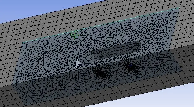
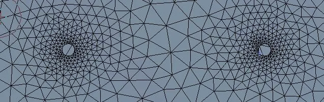
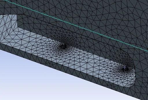
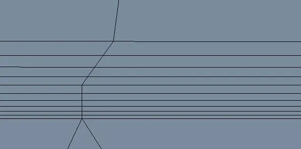
A total of 10 inflation layers were introduced at the wall of the Ahmed body. The size of the first cell is 5e-3m with a growth rate of 1.2 for every subsequent cell. The inflation layers are introduced to get accurate flow properties near the walls of the Ahmed body. Ideally, the size of first inflation layer cell must be in the range of 1e-5m as calculated using the online Yplus calculator 'Pointwise', but since providing this value increases the mesh element count drastically above the allowable limit for Ansys student version, the size of first inflation layer cell is taken as 5e-3m. There will be a total of 109930 and 36819 mesh elements and nodes respectively once the mesh is generated.
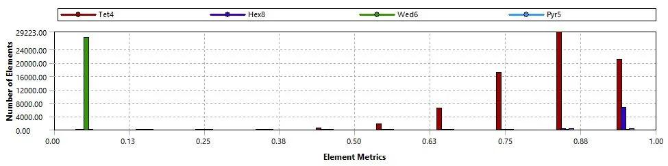
Overall, the majority of the mesh elements have mesh quality greater than 40%. From the above mesh quality report, we can see that almost all wed6 mesh elements have mesh quality of less than 10%, which is not good, this problem is mainly due to larger element size. This mesh quality can be reduced substantially if the mesh element size is reduced. This cannot be done since by doing so will increase the mesh elements above 0.5 million which is not allowed in Ansys student version. In the mesh independence study, we will reduce the mesh element sizing such that the total number of mesh elements does not exceed 0.5 million, and compare the obtained results.
4. Solving
The pressure-based solver is generally used for incompressible flow simulations whereas the density-based solver is used for compressible flow simulations. In this problem, we are simulating the flow over an Ahmed body for the fluid velocity of 25m/s. Even though this speed is nowhere close to the compressible flow, the density-based solver is used to perform this simulation so as to capture the compressibility effects of the fluid as it passes over the Ahmed body. The turbulence model used here is the K-omega SST. This model predicts well near the walls, hence this model is used to perform this simulation.
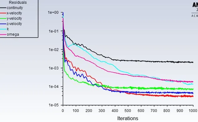
The solution was run using the steady-state solver for 1000 iterations, and from the trend of the residuals plot, we can say that the solution is converged after performing about 500 iterations.
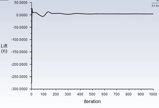
The lift produced by the Ahmed body is calculated. After the end of 1000 iterations, the value of the lift was found to be 3.4158N.
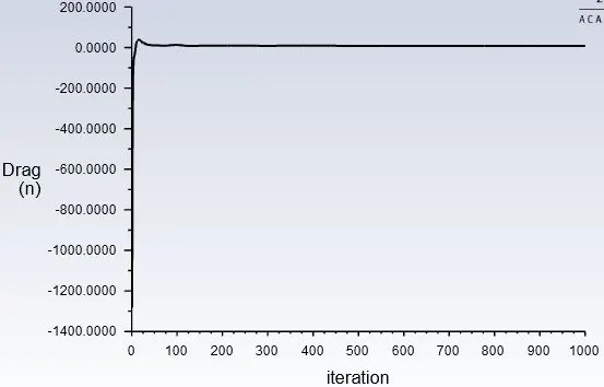
The drag produced by the Ahmed body is calculated. After the end of 1000 iterations, the value of the drag was found to be 8.0333N.
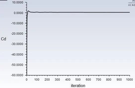
The coefficient drag produced by the Ahmed body is calculated. After the end of 1000 iterations, this value was found to be 0.3747. This value is close to the standard coefficient of drag result for the Ahmed body (0.33) for the fluid velocity of 25m/s, with air as the fluid. The accuracy of the solution can be improved by increasing the number of mesh elements and reducing the size of inflation layer cells.
5. Post-processing
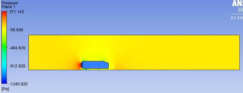
Pressure contours along the XY plane
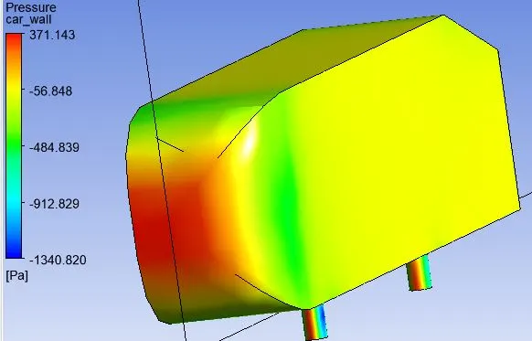
Pressure contours on the wall of the Ahmed body
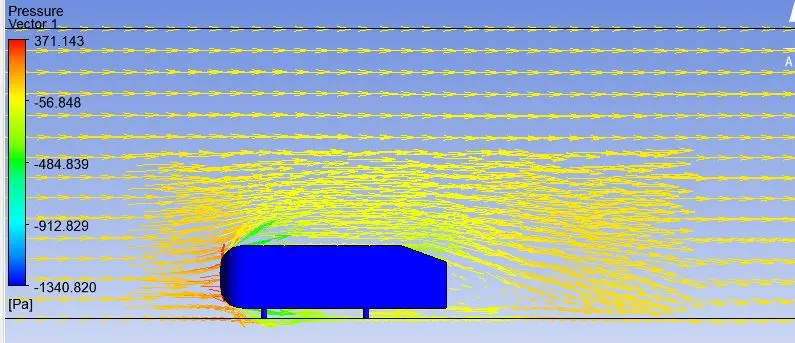
Pressure vectors along the XY plane. We an easily visualize the formation of the wake region near the rear of the Ahmed body.
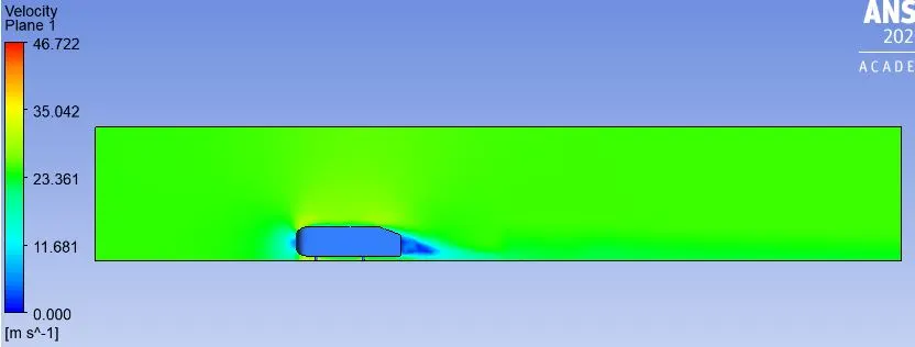
Velocity contours along the XY plane
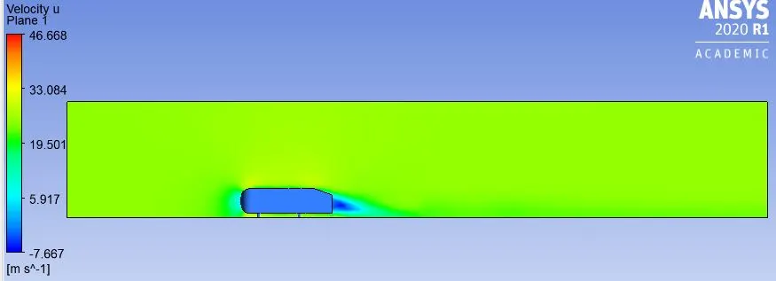
The above contours represent the velocity magnitude in the x-direction, along the XY plane. The negative velocity behind the Ahmed body represents the formation of vortices.
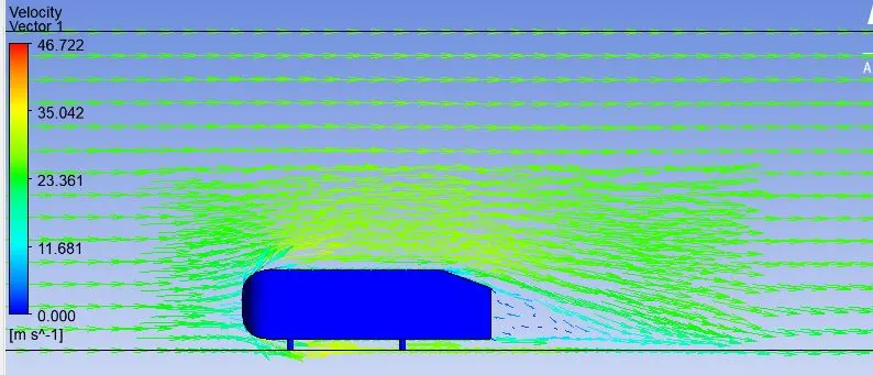
Velocity vectors along the XY plane. We an easily visualize the formation of the wake region near the rear of the Ahmed body.
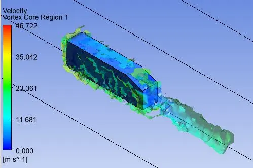
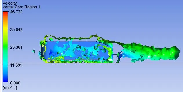
When the flow over the Ahmed body takes place, the front face area experiences a high pressure. Due to this, the flow diverges from the front face. The air flowing near the walls of the Ahmed body is higher than the average velocity. As the flow reaches the slanted part of the Ahmed body, the flow separation begins, which leads to the recirculation of flow. At the back face of the Ahmed body, this separation increases even more which leads to the formation of vortices. This region is called the wake region. The pressure in the wake region is usually lower (negative) to compensate for the increase in velocity and to overcome the shear stress. The position at which the boundary layer leaves the surface of a solid body is called the point of separation. In the case of the Ahmed body, the point of separation occurs near the slanted part of the body.
Mesh independence test:
1. Meshing
This test is done to check whether or not the accuracy of the solution obtained earlier is improved upon increasing the number of mesh elements. If there is a slight difference in the accuracy in the results obtained using a higher number of mesh elements, then the original mesh is said to be mesh independent(grid independent). Here, the bigger enclosure is provided with the multizone mesh of element size 0.06m. The smaller enclosure is provided with a tetrahedral mesh of element size 0.026m

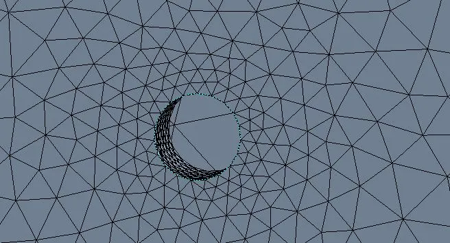
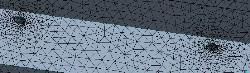
To obtain a smooth circular profile near the circular walls of the Ahmed body, the face sizing of 5e-3 is provided.
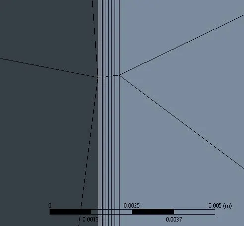
A total of 10 inflation layers were introduced at the wall of the Ahmed body. The size of the first cell is 5e-3m with a growth rate of 1.2 for every subsequent cell. The inflation layers are introduced to get accurate flow properties near the walls of the Ahmed body. Ideally, the size of first inflation layer cell must be in the range of 1e-5m as calculated using the online Yplus calculator 'Pointwise', but since providing this value increases the mesh element count drastically above the allowable limit for Ansys student version, the size of first inflation layer cell is taken as 5e-3m. There will be a total of 484711 and 130965 mesh elements and nodes respectively once the mesh is generated. In the Ansys student license, simulations containing up to 0.5 million can be solved, so this problem can be solved as the number of mesh elements lie within the limit provided by Ansys.
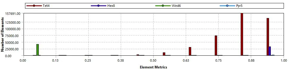
The quality of the mesh was evaluated, and since the majority of the mesh elements have the mesh greater than 50%, the mesh is said to be suitable to perform the simulations. The quality of the esh can be further improved if the mesh element size and the size of the first inflation layer cell are reduced, but this is not possible since doing so will increase the number of mesh elements above 0.5 million. Now that we have reduced the esh element size almost by 50%, there is a considerable improvement in the mesh quality. Now the proportion of mesh elements with mesh quality below 10% is much less compared to the previous mesh.

The solution was run using the steady-state solver for 1000 iterations, and from the trend of the residuals plot, we can say that the solution is converged after performing about 500 iterations.
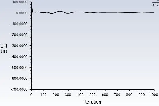
The lift produced by the Ahmed body is calculated. After the end of 1000 iterations, the value of the lift was found to be 4.6939N.
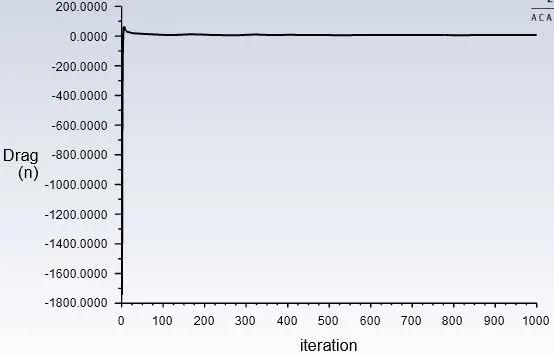
The drag produced by the Ahmed body is calculated. After the end of 1000 iterations, the value of the drag was found to be 6.7495N.
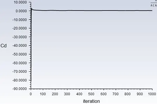
The coefficient drag produced by the Ahmed body is calculated. After the end of 1000 iterations, this value was found to be 0.31484. This value is close to the standard coefficient of drag result for the Ahmed body (0.33) for the fluid velocity of 25m/s, with air as the fluid. The accuracy of the solution has been improved compared to the solution obtained previously
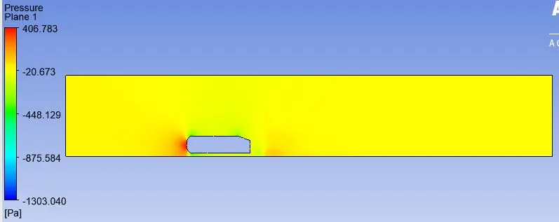
Pressure contours along the XY plane
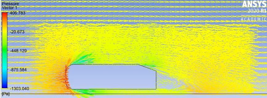
Pressure vectors along the XY plane. We can easily visualize the formation of the wake region near the rear of the Ahmed body.
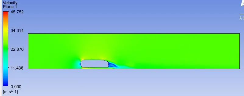
veloity contours along the XY plane
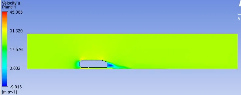
The above contours represent the velocity magnitude in the x-direction, along the XY plane. The negative velocity behind the Ahmed body represents the formation of vortices.
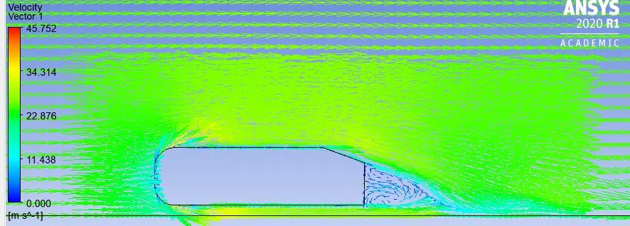
The results obtained in this simulation is definitely more accurate than the previous results. The velocity and pressure contours and vectors obtained give more detailed information than the previous case. Even though there is a substantial improvement in the accuracy of results obtained, it can be improved further by further reducing the mesh element size and solving it.
Results:
The results obtained by solving the given problem for 109930 and 484711 mesh elements respectively are given below:
| Number of mesh elements | 109930 | 484711 |
| Lift(N) | 3.541 | 4.693 |
| Drag(N) | 8.033 | 6.749 |
| Actual coefficient of drag(Cd) for flow velocity of 25m/s | 0.33 | 0.33 |
| Obtained coefficient of drag(Cd) for flow velocity of 25m/s | 0.374 | 0.314 |
| % error (Cd) | 13.33% | 4.848% |
Conclusions:
- To simplify the given problem, the geometry can be divided along its axis of symmetry, and the solution can be carried out. By doing so, the number of mesh elements required to solve the problem reduces, which subsequently reduces the solving time
- The accuracy of the solution increases with the decrease in the mesh element size. The accuracy of the solution near the Ahmed body is dependent on the size of the inflation layer cells. The accuracy of the solution increases if the inflation layer cell size is near Y-plus value.
- The Ahmed body produces a substantial amount of lift force as well. This is not good in an automotive engineering point of view since the lift decreases the traction between the tires and the road. To reduce this force, spoilers are used.