Advanced Sheet Metal Design Using NX Cad Challenge_7_ Metal bracket-II
METAL BRACKET
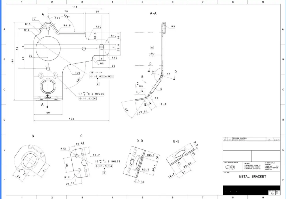
OBJECTIVE: The main objective of this project is to design the metal bracket from the given 2D drawing, using NX cad Sheet Metal Application.
INTRODUCTION:
A Bracket is a component used to support load or any attachments to structural element for heavy vehicle. It is subjected to different types of loading while the vehicle is in motion. One of the main common. loading is static load which is assumed to be constant throughout the operation. the best way to make simple brackets is sheet metal fabrication. One of the most common sheet metal processes is bending, in which a machine called a brake is used to bend sheet metal
DESIGN METHODOLOGY:
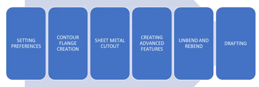
DESCRIPTION:
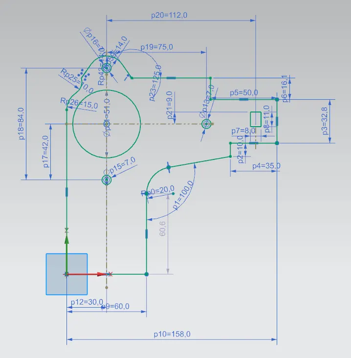
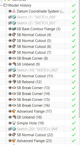
STEP 1: Creation of sketch in YZ plane in sketcher workbench
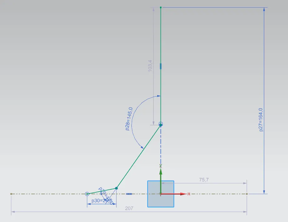
STEP 2: Creation of wall using CONTOUR FLANGE command in XY plane
STEP 3: Creation of NORMAL CUTOUTS from the skecth 1
STEP 4: Using BREAK CORNER option, creation of smooth corners
STEP 5: Now using UNBEND option the part is being unbended and a hole is created using NORMAL CUTOUT option
STEP 6: Rebending of part using REBEND option and smoothen the corners using BREAK CORNER option
STEP 7: Creation of flange using ADVANCED FLANGE option
STEP 8: Again Unbend the flange and creation of holes, slots using HOLE and NORMAL CUTOUT options
STEP 9: CReation of flange in the slot taken and Rebend the part using REBENDING option
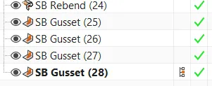
STEP 10: Finally, to provode stiffness to the bracket gussets are added using GUSSET command
ORIENTATIONS OF METAL BRACKET:
ISO VIEW
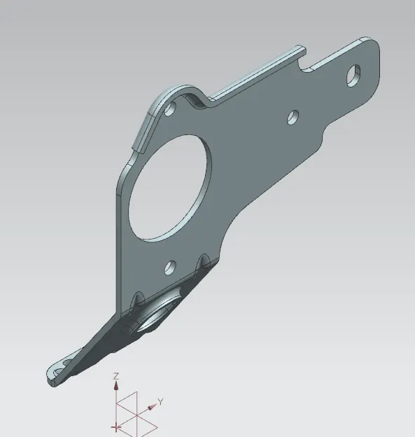
FRONT VIEW
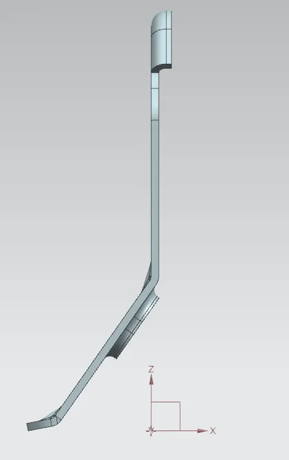
TOP VIEW
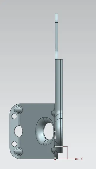
RIGHT VIEW
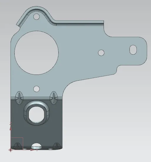
MODEL TREE:
GIVEN DRAWING SHEET
CONCLUSION: The principles of Sheet metal design were practiced and understood while modelling of Metal Bracket using various features and tools in NX CAD