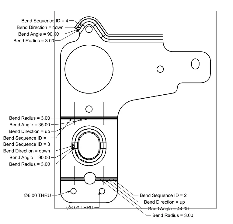
Advanced Sheet Metal Design Using NX Cad Challenge_7_ Metal bracket-II
NX_Bracket-II_Harishanth
Aim:
To create Sheet Metal Component with Sheet Metal modelling tools applied throughout the modelling using NX.
Introduction:
In this we are going to create sheet metal Bracket step by step using seimens NX sheetmetal applicatiion.
Design methodology:
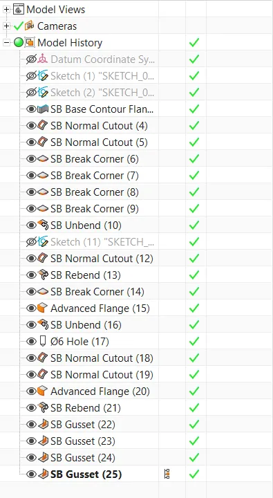
Procedure:
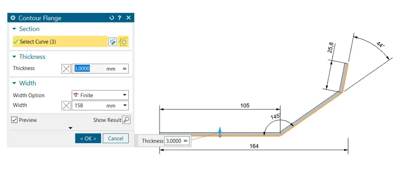
Step 1: Contour flange
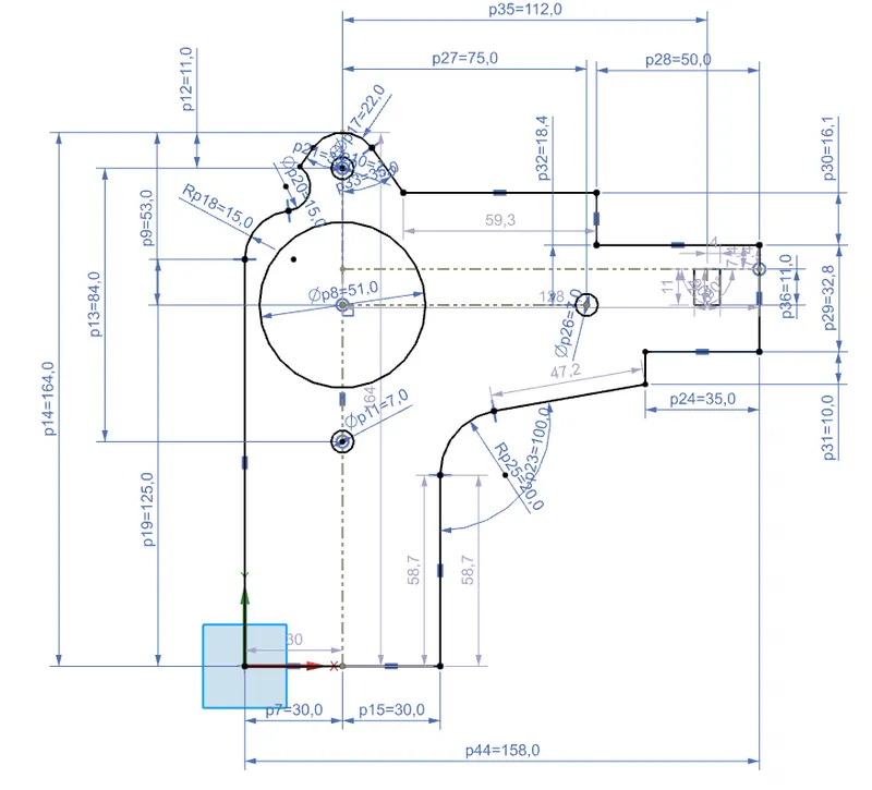
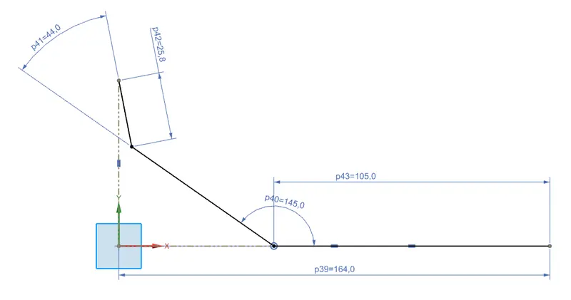
- Start Nx and create new file then the first step is to draw two sketch as shown in different planes and exit sketch.
- Click on the button contour flange
 on the tab and select second sketch give the value as shown.
First sketch in XY plane:
Second sketch in YZ plane :
Contour flange:
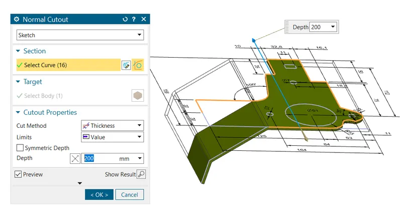
Step 2: Normal cutout
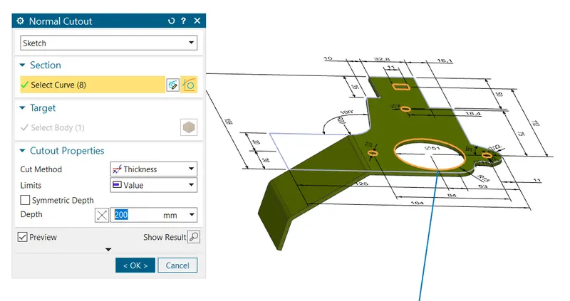
- Click the button normal cutout from the tab
 and then select the second sketch for cutting out the material to obtain the shape.
First select outer profile to cutout:
Second give the hole and other profile inside them for cutout step by step.
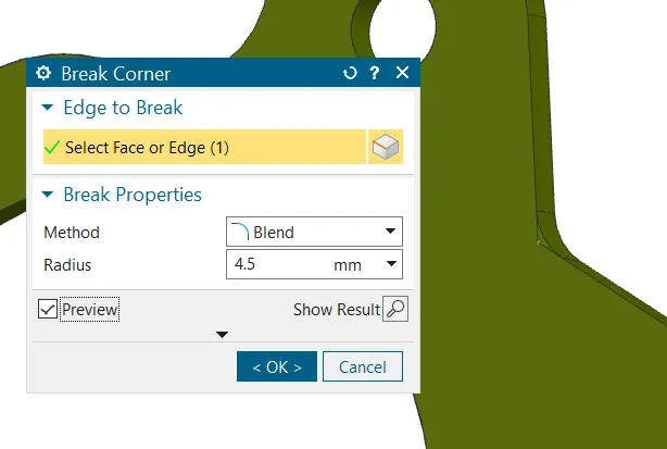
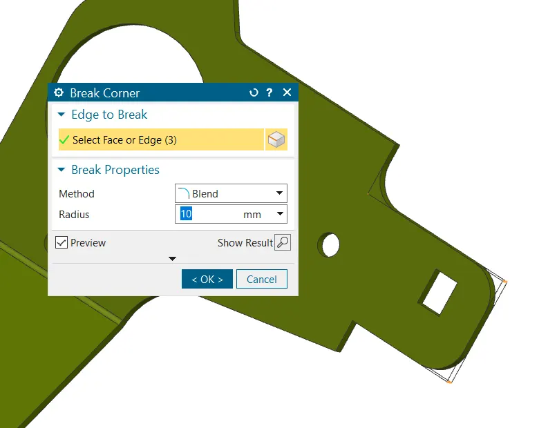
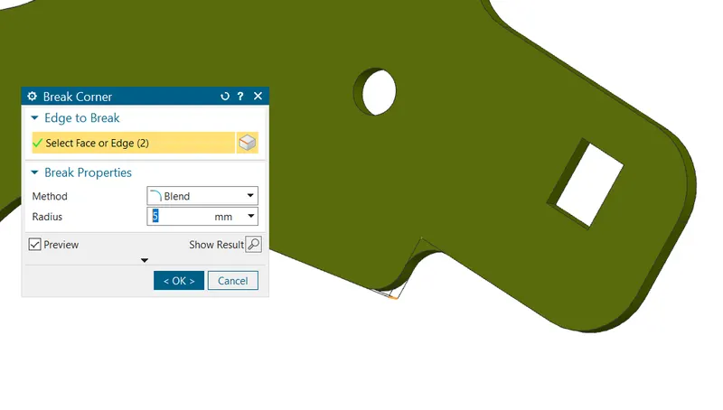
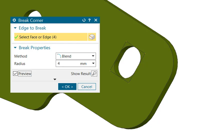
Step 3: Break corner
 We need to give various dimension of radius for different edges to remove sharp edges.
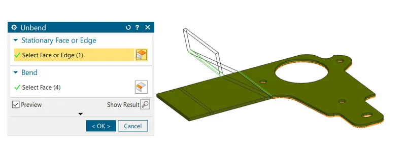
Step 4: Unbend
- Select the button
 and click the face which is need to be base and give the rest to unbend as shown.
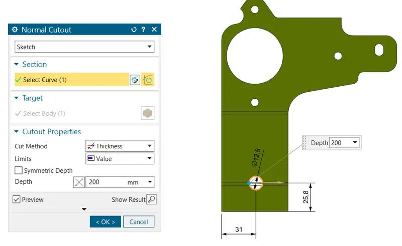
Step 5: Normal cutout
- Click the button normal cutout from the tab and draw a sketch as shown then select the sketch for cutting out the material to obtain the shape.
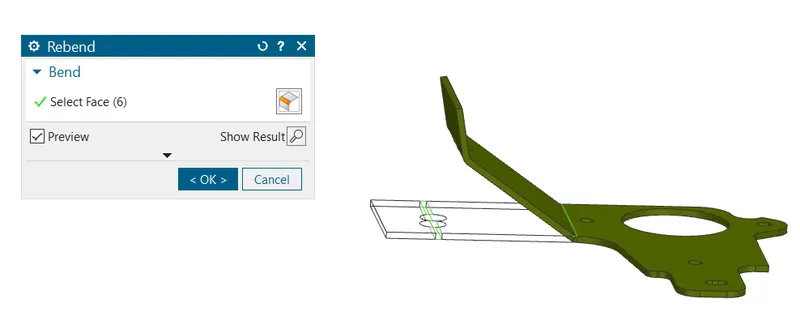
Step 6: Rebend
- Rebend the faces by selecting them in reverse order in which they were bend as shown.
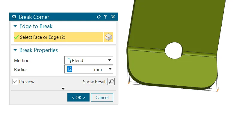
Step 7: Break corner
- We need to give radius for edges as shown .
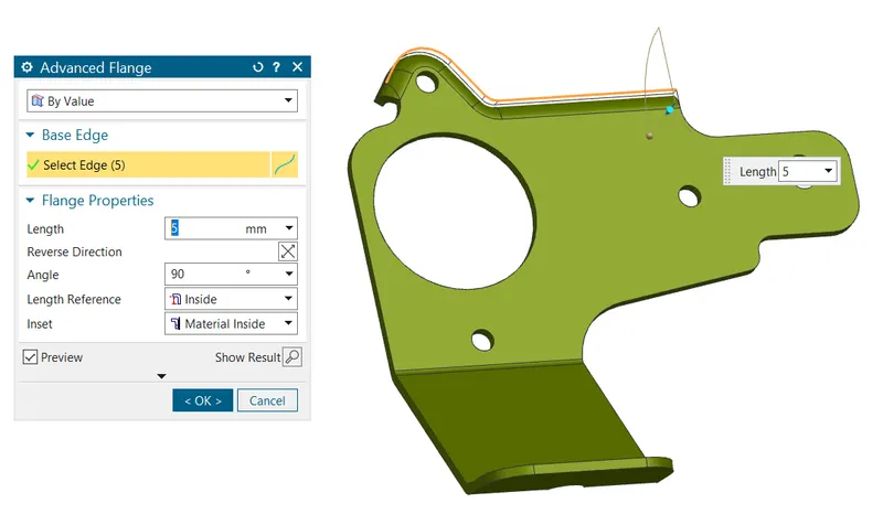
Step 8: Advanced flange
- Similar to contour flange select the edge as shown to get the desired flange and give the as shown.Search for this tool in command finder.
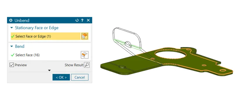
Step 9: Unbend
- Select the button and click the face which is need to be base and give the rest to unbend as shown.
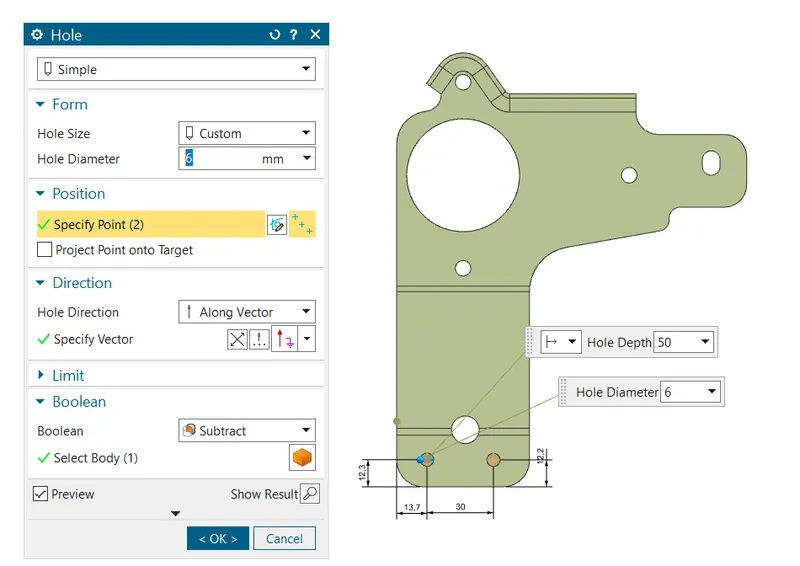
Step 10: Hole
- After unbending the sheet add features such as holes as shown get the feature from command finder by typing hole.
- Then sketch the point for hole position and select these points for the hole position.
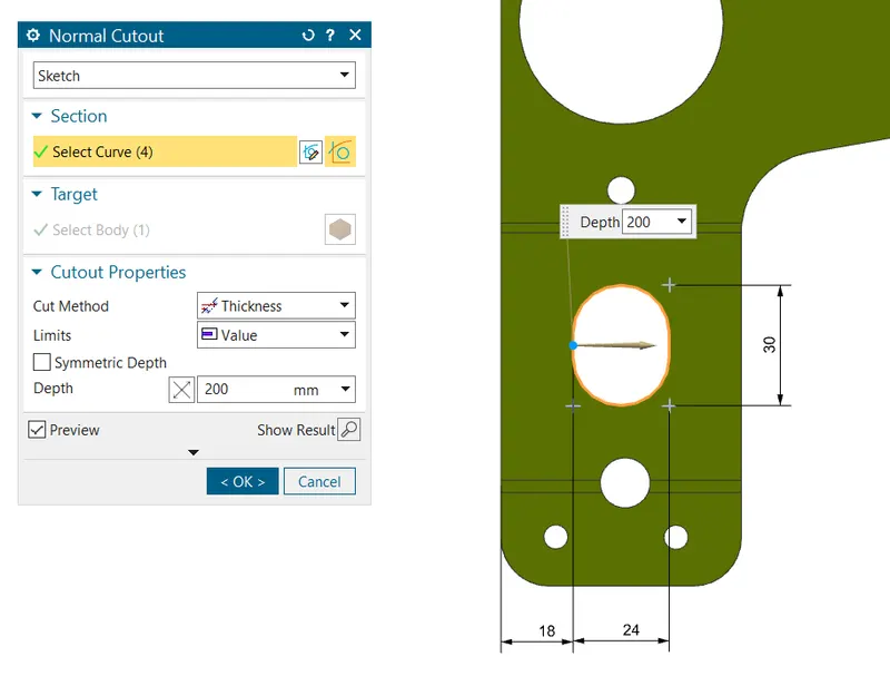
Step 11: Normal cutout
- Click the button normal cutout from the tab and draw a sketch as shown then select the sketch for cutting out the material to obtain the shape.
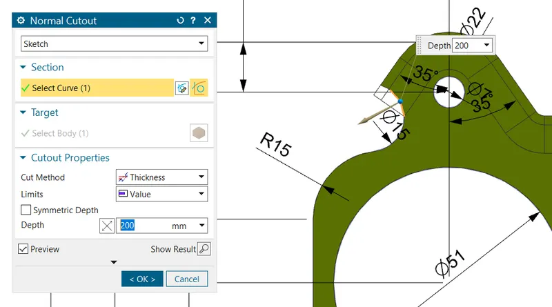
Cutout the profile in first sketch from the advanced flange we made as shown.
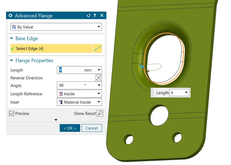
Step 12: Advanced flange
- Similar to previous advanced flange this time select the cutout edge for the flange option and give value as shown.
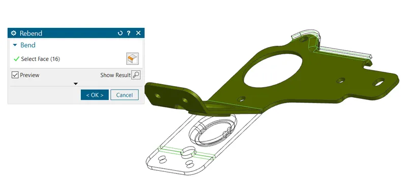
Step 13: Rebend
- Rebend the faces by selecting them in reverse order in which they were bend as shown.
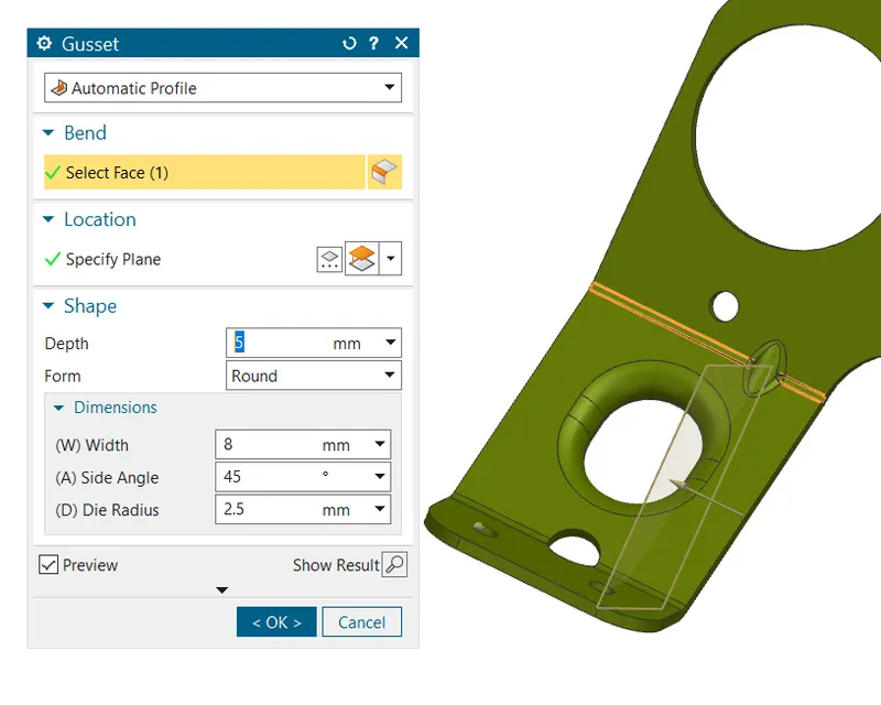
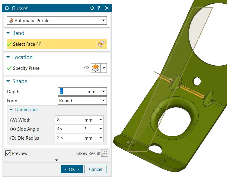
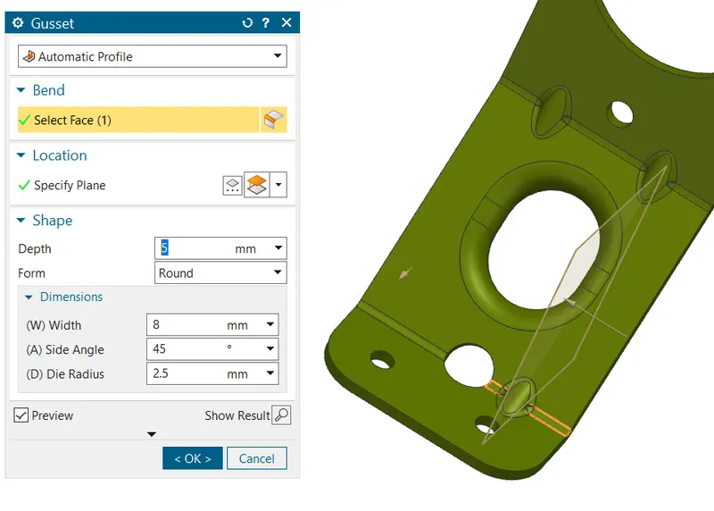
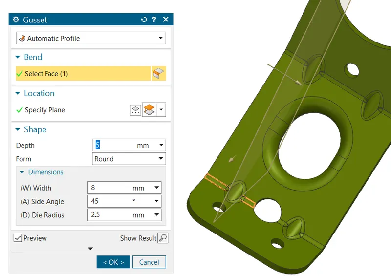
Step 14: Gusset
- From punch tab select the gusset
 option from more gallery and then select the bend face on which gusset has to be given and give the position by giving distance from a face which is selected as plane.
 - In total four gusset has to be given and each has to be given seperately
Model view:
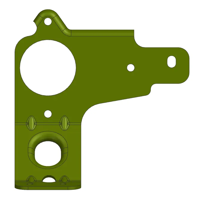
Top view
Front view
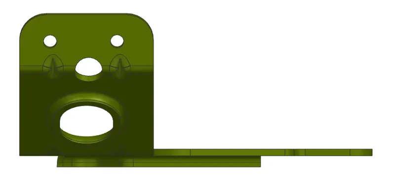
Right view
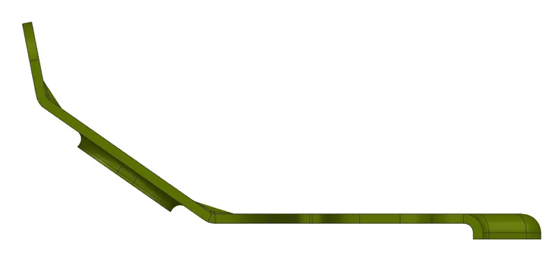
Isometric view
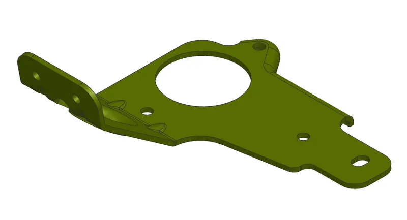
Result: Drafting
- Go for drafting ctrl + shift + D as shortcut a window will pop-up then give paper size and select the flat pattern as view in base view .
- Then delete the unwanted text generated along with it you can also give further dimensions and print them if need.