Week -2
Doorbell:
Model link:
https://drive.google.com/file/d/1D5_G0Y3XqBSTnWt9KLW1sENKLINAHRPZ/view?usp=sharing
Report:
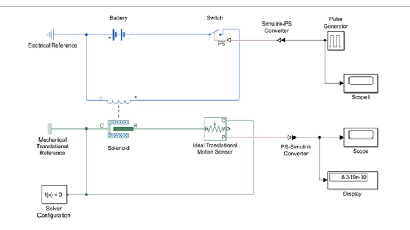
For doorbell the simple circuit using solenoid is connected with battery, switch and ideal translation motion sensor.
Then for switch an input signal has to be given using pulse generator to Simulink-PS converter to switch.
The output from ideal translation motion sensor signal is given to PS-Simulink converter to scope and display.
Reference for each circuit has connected and solver configuration is also given to solenoid circuit.
Thermistor:
Model link:
https://drive.google.com/file/d/1-6llEzwqOpVN2WkS8O1UzME50osBFnG1/view?usp=sharing
Report:
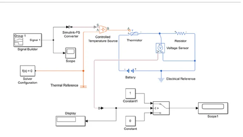
The same concept is used for thermistor where the circuit consist of thermistor, resistance, voltage sensor and battery.
Then further the temperature source has to be given where it has to be controlled by the input signals so the signal builder is used for signals.
The controlled temperature source has to be given in kelvin so the signals is in kelvin with respect to time. Then connected to thermistor.
Signal from signal builder is in kelvin so Simulink-PS converter parameters has to be in kelvin and input handling is changed for more derivatives as shown in report.
The output from voltage sensor is connected to switch then to scope to monitor fan on/off condition
All the reference is connected and solver configuration is connected to temperature source.
From output scope we can understand that from 0-10 sec the heater fan is on and from 10-30 sec the fan is off and again from 30-50 sec at 296K the fan is on.