Week - 4
1.Washing machine:
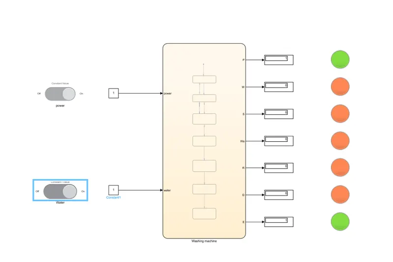
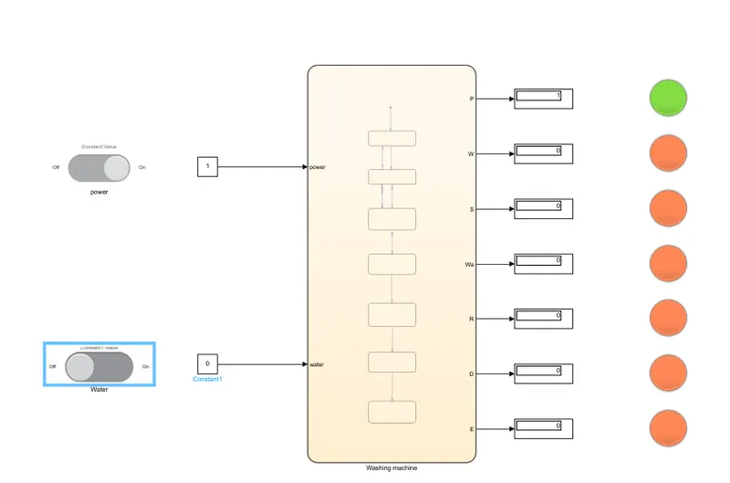
- Two inputs power and water supply is controlled with slider switch.
- They are connected to seperate constant blocks.
- If the switch is on the constant shows 1 and similarly for off shows 0.
model:
https://drive.google.com/file/d/1dd1gP5qKlUp7G4ZoUhW2xp6eF2pPgu0Y/view?usp=sharing
stateflow:
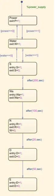
- To implement the condition chart is used to stateflow power is the first state to begin
- Then water and each stage is given the proper conditions for entry and exit.
- For transition the time given for each input is set as condition as seen.
- The display and lamps are used to get the output.
- Inside chart the symbol plane is used to assign the inputs and outputs.
Results:
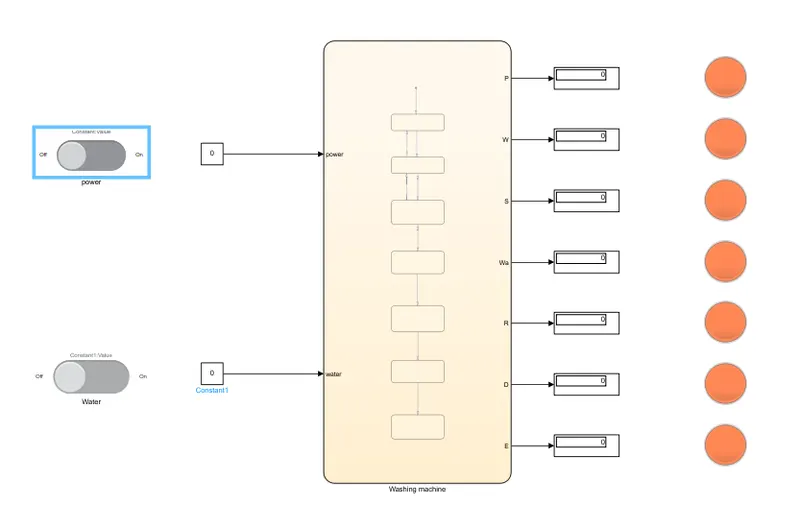
1 When power supply is missing:
2 when water supply is missing:
2.Gear shift logic:
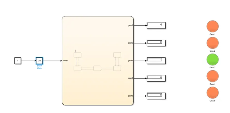
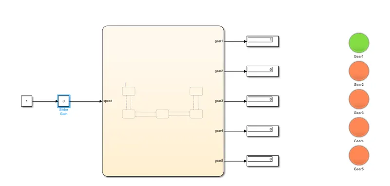
- A constant block is connected to a slider gain block for the input speed to be given to chart.
- Chart is used to set the state flow for the gear shift logic condition.
- Inside the chart five gear blocks is used and each assigned with some conditons as shown in model.
model:
https://drive.google.com/file/d/11AGwzKEdeTB_RtCr4cfCI-ZP1evWWUH0/view?usp=sharing
Stateflow:
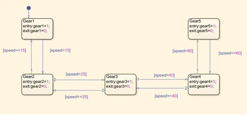
- After the condition given to each gear block then the same is done for transition.
- From the given data speed range the conditions are set for the transition as shown in state flow.
- For the output display and lamp is used to indicate the gear state.
- In the chart the symbol plane is used to assign the inputs and outputs.
Result:
when speed is in 0-15:
When the speed is in 26-40: