Advanced Sheet Metal Design Using NX Cad Challenge_7_ Metal bracket-II
Title: Design of Metal Bracket using NX cad Sheet Metal Application
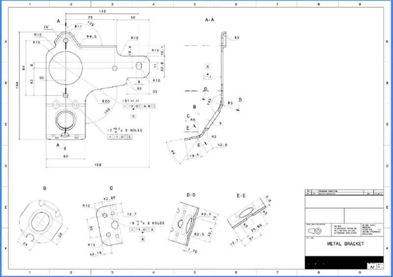
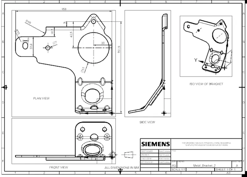
Objective: The main objective of this project is to design the metal bracket from the given 2D drawing, using NX cad Sheet Metal Application.
Introduction: The Bracket is designed from the given 2D drawing.
The basic features of sheet Metal like contour flange, Normal cut-outs, break corner, Unbend and Rebend options are used.
Advanced features like advanced flange, Gusset, and Hole options are used.
To start with the design first we must sketch the Front side view of the Metal bracket from the given 2D drawing. Then the basic feature tab is created using the contour flange command.
Contour Flange:
This command is used to create a base feature by extruding the sketch along a vector or adding material by sweeping a sketch along an edge or chain of the edges.
Normal Cut-out:
This command is used to cuts the material by projecting a sketch onto the model and then cutting perpendicular to the faces intersected by the projection.
Break Corner:
This command is used to create Rounds or chamfers in a sharp corner of a tab or flange.
Unbend & Rebend:
Unbend command is used to flatten a bend and a material adjacent to the bend. Rebend command is used to restore an unbend feature to its previous bend state, along with ant features added after the unbend feature.
Advanced Flange:
This command is used to add a flange along an edge using a bend angle or a reference face. The Edge and reference face can be curved.
Gusset:
This command is used to create a stiffening gusset on the part. It is usually made to add strength to the sheet metal part.
Hole:
This command is used to create a hole to one or more solid bodies in a part or assembly with options for Countersunk, Counterbored, and threaded.
Design Methodology:
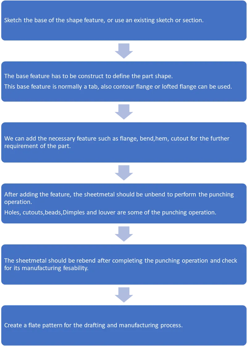
Descriptions:
Step 1: Creating the Front side view sketch in the XZ plane
The front view of the given 2D drawing is created on the front plane with the given dimension.
Step 2: Contour Flange
After the sketch, the base feature of the part is created using the contour Flange command.
Step 3: Creating the Profile sketch
In the Right-side view of the base feature, the profile sketch is created as per the given drawing.
Step 4: Normal Cut-out
After the profile sketch, then the cutting operation is performed using the Normal cut-out option.
Step 5: Unbend and Normal cut-out
To make the hole in the bend region of the sheet metal part, then it must be Unbend. Then the sketch is drawn in the unbend condition and then the hole is created using a Normal cut-out.
After creating the Hole with a Normal cut-out, it can be Rebend to the original shape.
Step 6: Break Corner
The sharp edges of the sheet metal part are blended using the Break corner command wherever needed.
Step 7: Advanced Flange
On the top edge of the model advanced flange is created as per the given drawing.
Step 8: Unbend & Normal cut-out
After that, the sheet metal is unbending and the normal cut-out is performed as per the drawing.
Then Advanced flange is performed in the created hole.
Step 9: Rebend
Then the sheet metal is Rebend after creating all the features.
Step 10: Gusset
The 4 Gusset is created as per the drawing. This gives extra strength to the sheet metal part.
Step 11: Hole
The simple hole is created as per the dimension provided in the 2D drawing.
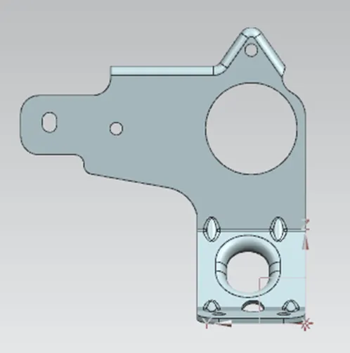
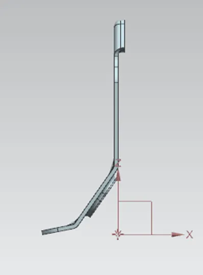
Different Views of Bracket: -
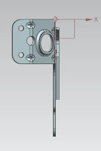
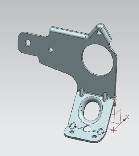
DETAILED DRAWING IMAGE-
CONCLUSION
The bracket is designed as per the given detail.