Advanced Sheet Metal Design Using NX Cad Challenge_7_ Metal bracket-II
Write a detailed report on Sheet Metal Component with good explanation on Sheet Metal modelling tools applied throughout the modeling. Also attach the Final model Images (Min. 4 images) of Sheet Metal Bracket.
METAL BRACKET USING NX SHEET METAL design:
OBJECTIVE:
This is a project to learn the step-by-step procedure to create a Bracket with a gusset from the given 2D drawing.
INTRODUCTION:
Sheet metal is simply metal formed into thin and flat pieces. It is one of the fundamental forms used in metalworking and can be cut and bent into a variety of different shapes Countless everyday objects are constructed of the material. Thicknesses can vary significantly, although extremely thin thicknesses are considered foil or leaf, and pieces thicker than 6 mm (0.25 in) are considered plate.
Metal Forming Process
Forming can be defined as the process in which the desired size and shape of the object are obtained through the plastic deformation of the material. The stresses induced during the process are greater than yield strength but should be less than the fracture strength. Different types of loading may be used depending on the process.
Sheet metal processing
The raw material for sheet metal manufacturing processes is the output of the rolling process. Typically, sheets of metal are sold as flat, rectangular sheets of standard size. If the sheets are thin and very long, they may be in the form of rolls. Therefore the first step in any sheet metal process is to cut the correct shape and size ‘blank’ from a larger sheet.
Sheet metal forming processes Sheet metal processes can be broken down into two major classifications and one
minor classification
Shearing processes -- processes that apply shearing forces to cut, fracture, or
separate the material.
- Forming processes -- processes that cause the metal to undergo desired shape
changes without failure, excessive thinning, or cracking. This includes bending
and stretching.
• Finishing processes -- processes that are used to improve the final surface
characteristics.
DESIGN METHODOLOGY:
DATA FROM 2D SKETCH

COUNTOUR FLANGE IS CREATED FOR THE SKETCH
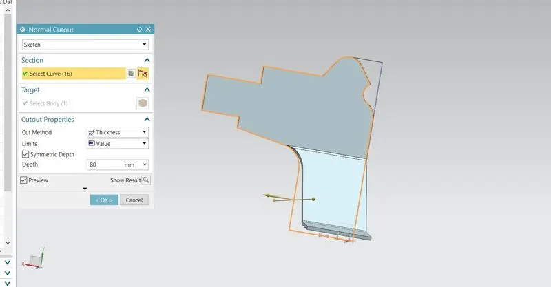
NORMAL CUTOUT IS USED TO ACHIEVE THE DECIDED SHAPE
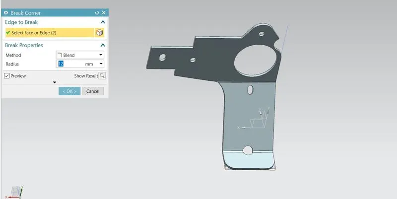
BREAK CORNER IS USED TO ACHIEVE A SMOOTH EDGE
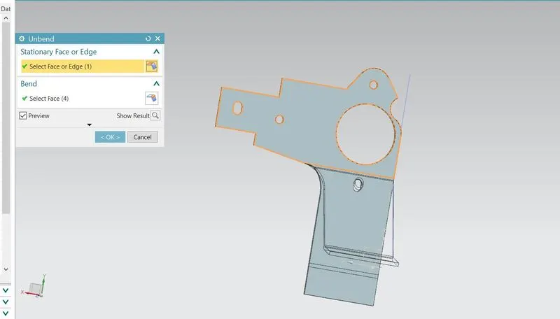
UNBEND IS PERFORMED FOR THE MODEL
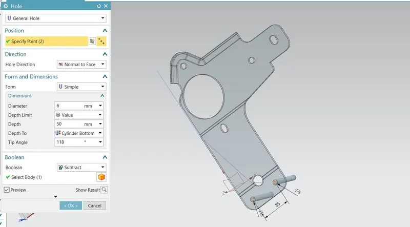
HOLES ARE CREATED ON TOP OF THE SURFACE
REBEND COMMEND IS USED
ADVANCED FLANGE IS CREATED
A HOLE IS CREATED AND AN ADVANCED FLANGE COMMAND USED
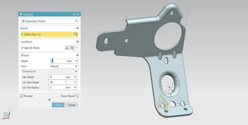
GUSSET IS ON BEND TO INCREASE THE STRENGTH
FINALLY 2D SKETCH IS CREATED
Description
SKETCH IS CREATED FOR THIS MODEL IN XY PLINE SECOND SKETCH IS CREATED ON
YZ PLINE
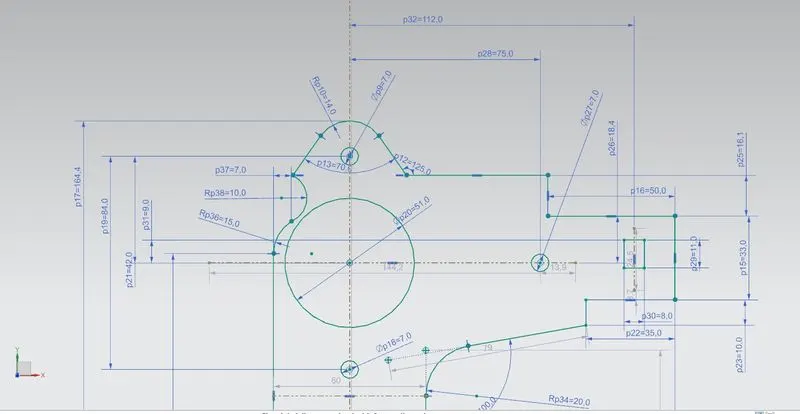
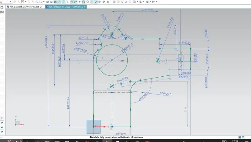
THE SECOND SKETCH IS SHOWN BELLOW
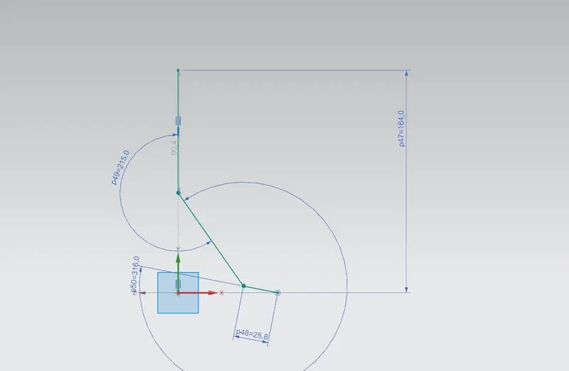
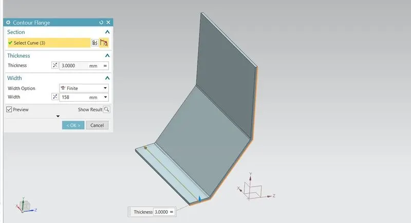
COUNTOUR FLANGE IS COMMAND IS USED WITH THE REFERENCE OF SKETCH 2 WITH THICKNESS OF 3 MM AND THE WIDTH OF 158 MM
THEN NORMAL CUTOUT IS USED WITH THE REFERENCE OF SKETCHING ONE IMAGE AS SHOWN BELOW OF VISUAL CLARITY
BREAK CORNER IS PERFORMED IN EACH CORNER TO ACHIEVE SMOOTH CUEVE
UNBEND COMMAND IS USED AND SHOWN BELLOW
A HOLE IS CREATED AS SHOWN IN THE SKETCH
THE NORMAL CUT-OUT IS DOWN HERE AS SHOWN IN THE BELOW IMAGE

ADVANCED FLANGE IS CREATED ON THE TOP OF THE SURFACE IMAGE IS SHOWN BELOW
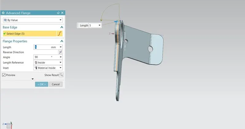
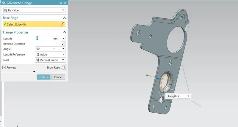
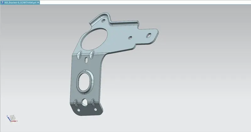
GUSSET IS CREATED ON THE BEND TO IMPROVE THE STRENGTH WITH THE DEPTH OD 5 MM
SAMPLE IMAGE
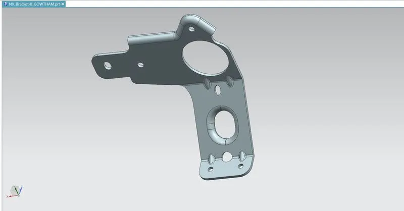
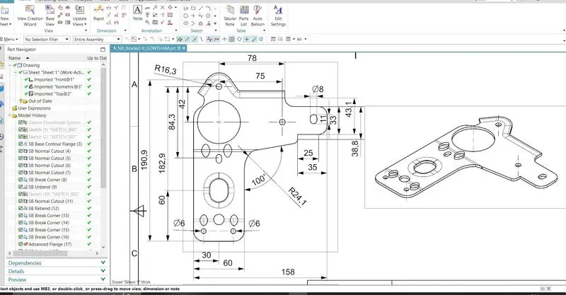
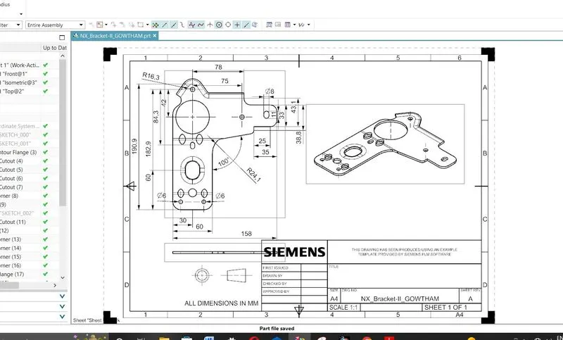
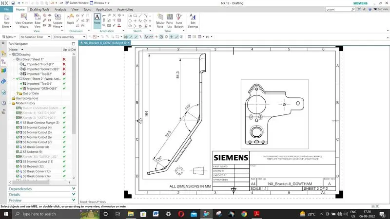
2D DRAFTING IS CREATED AND SHOWN BELOW
CONCLUSION:
The sheet metal bracket is designed and created successfully using the NX CAD SOFTWARE. From this project, we get to understand advanced flange and gusset features while working on it.