Advanced Sheet Metal Design Using NX Cad Challenge_7_ Metal bracket-II
METAL BRACKET 2
Objective:
To design ah sheet metal bracket by using NX CAD sheet metal work bench.
Introduction:
- It is a robust 3D solution that provides fast and realistic concept design and modeling.
- Superior in power and flexibility.
- NX CAD design tools are setting new standards for speed performance and ease of use.
- It supports modeling of complex surfaces, solids and advanced free form modeling (Sheet Metal).
- It is also known as Unigraphics.
Design Methodology:
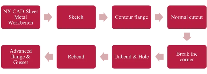
Commands used while designing:
- Contour flange
- Normal cutout
- Break corner
- Unbend
- Rebend
- Advanced flange
- Hole
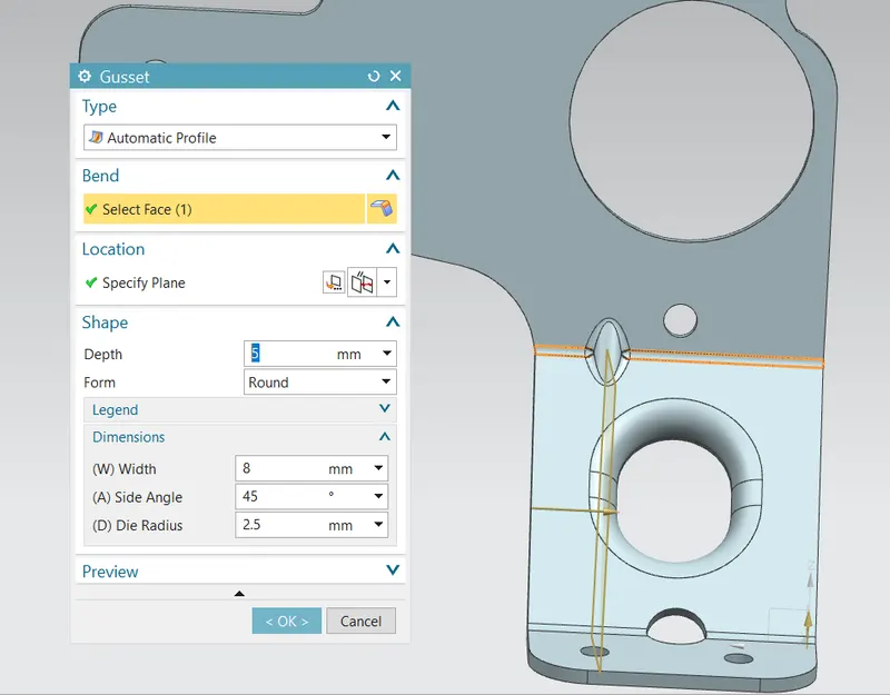
- Gusset
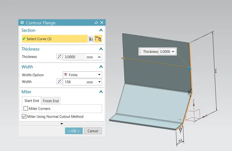
1.Contour flange:
Creates a base feature by extruding a sketch along a vector or adds material by sweeping a sketch along an edge or chain of edges.
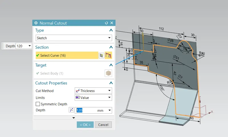
2. Normal cutout:
Cuts a material by projecting a sketch on to the model and then cutting perpendicular to the faces intersected by the projection.
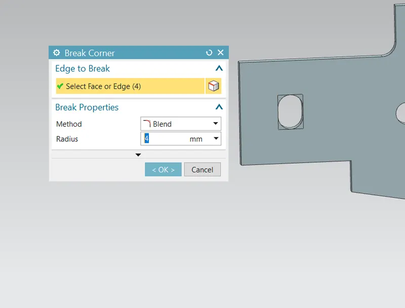
3. Break corner:
Rounds or chamfers a sharp corner of tab or flange.
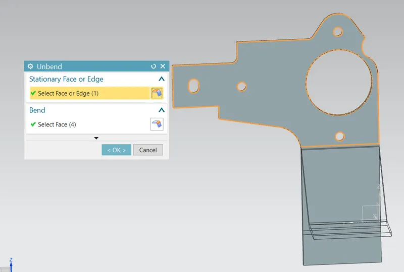
4.Unbend:
Flattens a bend and the material adjacent to the bend.
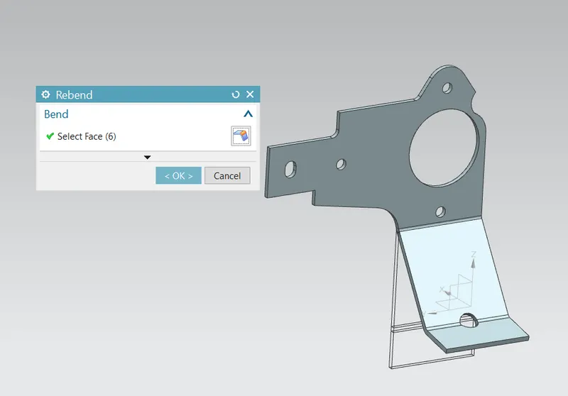
5.Rebend
Restores an unbend feature to its previous bend state along with any features added after the unbend feature.
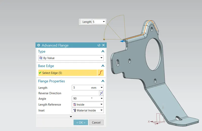
5.Advanced flange:
Adds a flange along an edge using a bend angle or a reference face. The edge and reference face maybe curved.
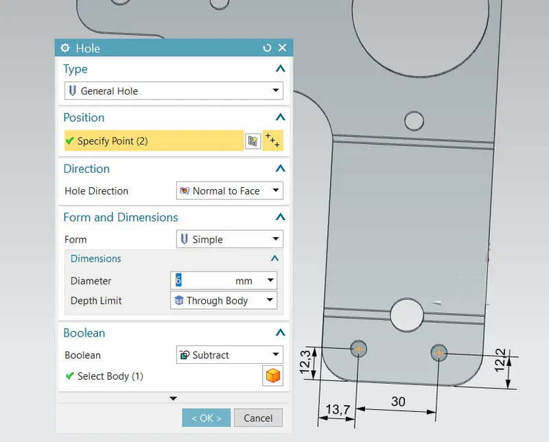
6.Hole:
Adds a hole to one or more solid bodies in a part or assembly with options for counterbored, countersunk and threaded.
7.Gusset:
Creates a stiffening gusset on the part.
Front view:
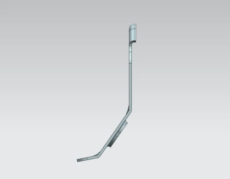
Right Side view:
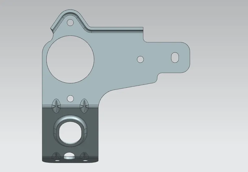
Left Side view:
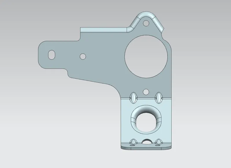
Top view:
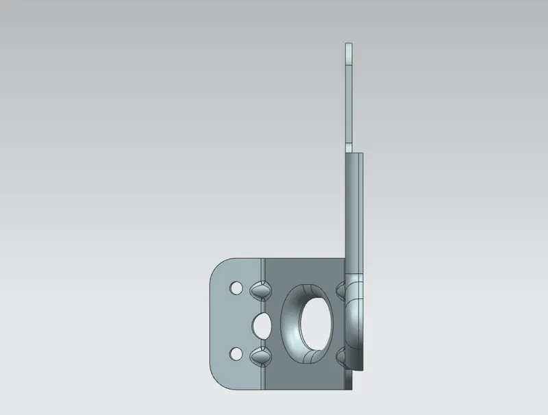
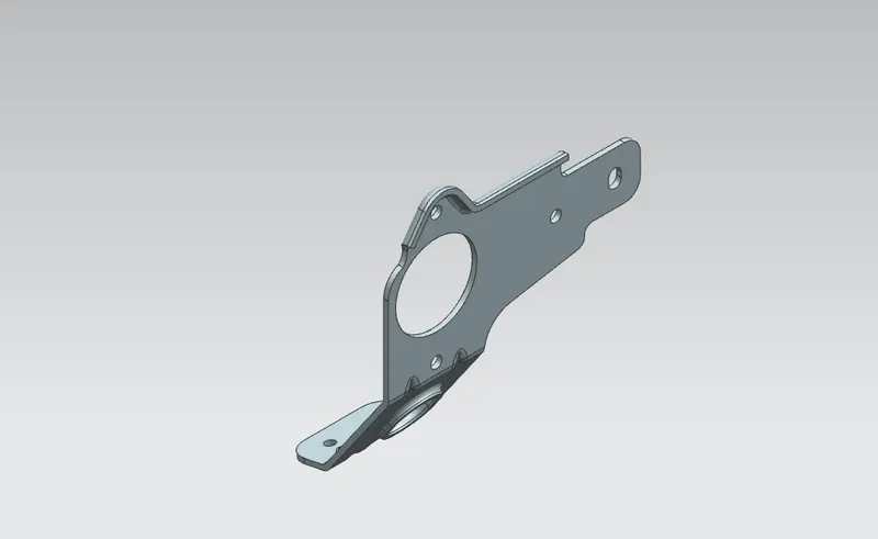
Isometric view:
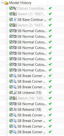
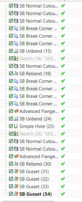
Tree Structure:
Conclusion:
Metal Bracket has been designed by using NX CAD sheet metal workbench.