Advanced Sheet Metal Design Using NX Cad Challenge_7_ Metal bracket-II
METAL BRACKET 2
OBJECTIVE
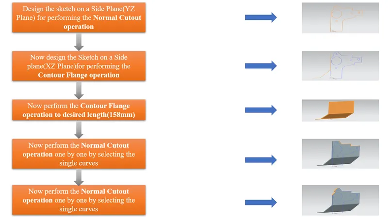
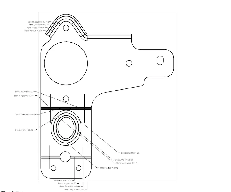
The main objective of this challenge is to design the Metal Bracket 2 by taking the reference of given 2D drawing and only use the Sheet Metal Feature to design it.
INTRODUCTION
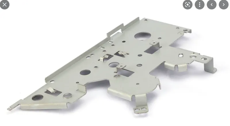
- Sheet Metal Fabrication is the process of forming parts from a metal sheet by punching, cutting, stamping, and bending. 3D CAD files are converted into machine code, which controls a machine to precisely cut and form the sheets into the final part. Sheet metal parts are known for their durability, which makes them great for end use applications (e.g. chassis). Parts used for low volume prototypes, and high volume production runs are most cost-effective due to large initial setup and material costs. Because parts are formed from a single sheet of metal, designs must maintain a uniform thickness. Be sure to follow the design requirements and tolerances to ensure parts fall closer to design intent and cutting sheets of metal.
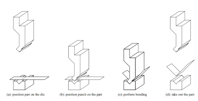
- Bending is a process whereby a force is applied to sheet metal which causes it to bend at an angle and form the desired shape. Bends can be short or long depending on what the design requires. Bending is performed by a press brake machine that can be automatically or manually loaded. Press brakes are available in a variety of different sizes and lengths (20-200 tons) depending on the process requirements.
CRITICAL DIMENSIONS OF BENDING A SHEET
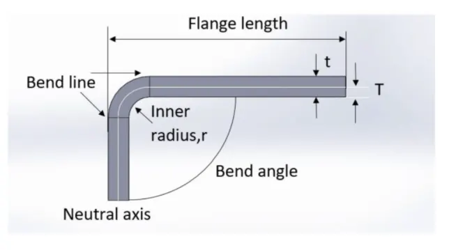
The following are some terminology that are used in sheet metal. Designers need to adhere to machinery guidelines when designing for bending. Bends can be characterised by these parameters. Some critical dimensions that need to be considered when setting up sheet metal in CAD software are sheet metal thickness, the k-factor and bend radius. One needs to check that these factors are consistent with the tooling that will be used in manufacturing. This guide gives important guidelines for good design practice.
Bend line– The straight line on the surface of the sheet, on either side of the bend, that defines he end of the level flange and the start of the bend.
Bend radius – The distance from the bend axis to the inside surface of the material, between the bend lines.
Bend angle – The angle of the bend, measured between the bent flange and its original position, or as the included angle between perpendicular lines drawn from the bend lines.Sometimes specified as the inside bend radius. The outside bend radius is equal to the inside bend radius plus the sheet thickness.
Neutral axis – The location in the sheet that is neither stretched nor compressed, and therefore remains at a constant length.
K-factor – The location of the neutral axis in the material, calculated as the ratio of the distance of the neutral axis T, to the material thickness t. The K-factor is dependent upon several factors (material, bending operation, bend angle, etc.) and is greater than 0.25, but cannot exceed 0.50. K factor = T/t
The K-factor is used to calculate flat patterns because it is related to how much material is stretched during bending. Therefore it is important to have the value correct in CAD software. The value of the K-factor should range between 0 – 0,5.
Bend allowance – The length of the neutral axis between the bend lines or the arc length of the bend. The bend allowance added to the flange lengths is equal to the total flat length.
DESIGN METHODOLOGY
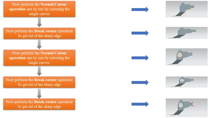
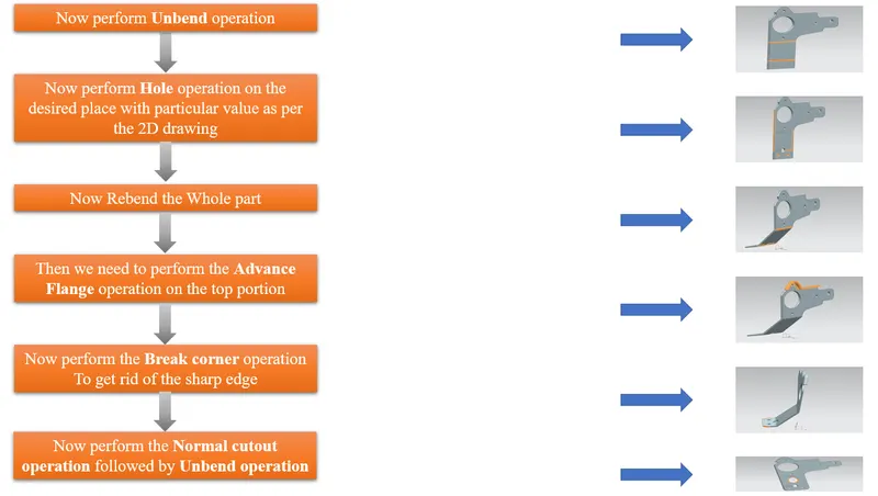
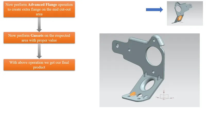
ORIENT VIEW
Left Side view
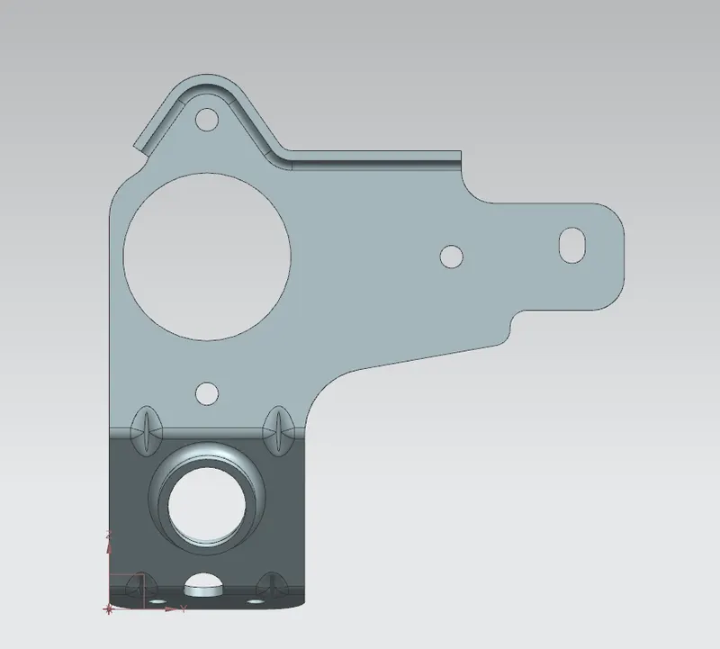
Front View
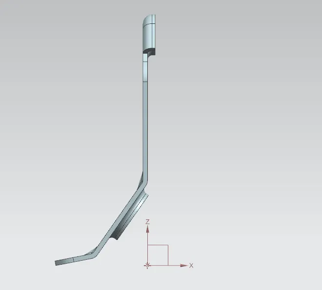
Top View
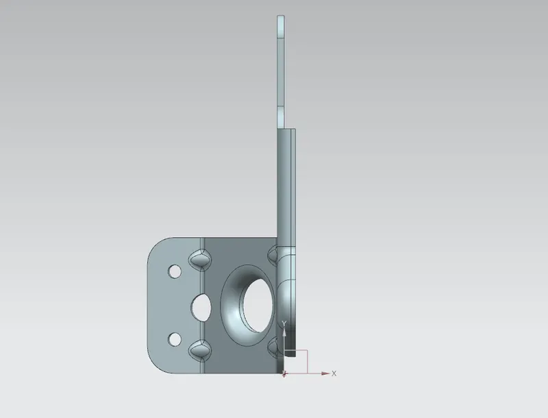
Isometric View
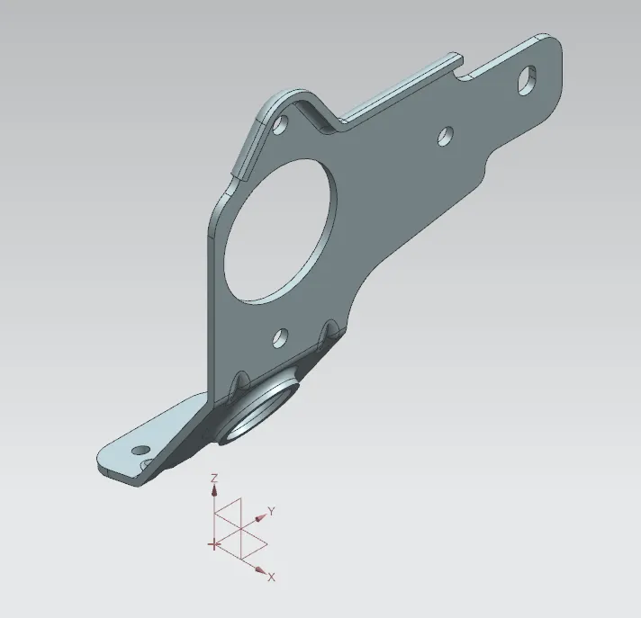
Flattern View
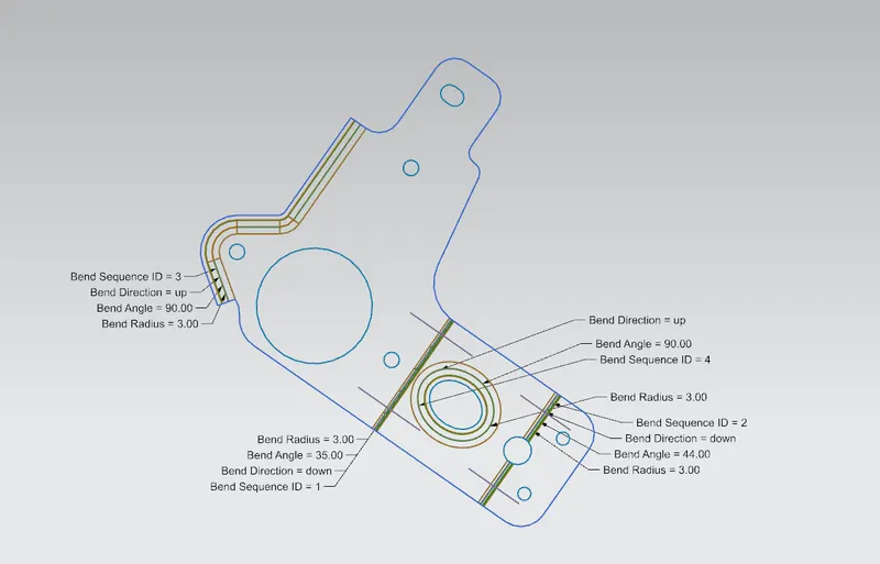
In Drafting Sheet
CONCLUSION
In this challenge we get to know that the different tools like Advance flange,Normal Cut out,Gusset etc.