Advanced Sheet Metal Design Using NX Cad Challenge_7_ Metal bracket-II
DESIGN OF SHEET METAL BRACKET 2 :
OBJECTIVE :
To design a sheet metal bracket from a 2D sketch with help of NX CAD tool features.
INTRODUCTION :
A bracket is an architectural element: a structural or decorative member. It can be made of wood, stone, plaster, metal, or other media. It projects from a wall, usually to carry weight and sometimes to strengthen an angle.In mechanical engineering a bracket is any intermediate component for fixing one part to another, usually larger, part. What makes a bracket a bracket is that it is intermediate between the two and fixes the one to the other. Brackets vary widely in shape, but a prototypical bracket is the L-shaped metal piece that attaches a shelf (the smaller component) to a wall (the larger component): its vertical arm is fixed to one (usually large) element, and its horizontal arm protrudes outwards and holds another (usually small) element.
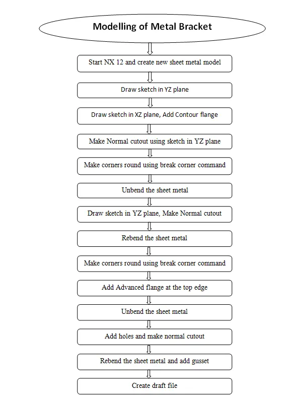
DESIGN METHODOLOGY :
DESCRIPTION :
CONTOUR FLANGE :
This command is used to create a flange by extruding a sketch along a vector,or by sweeping a sketch along an edge or chain edge.NX adds bend automatically using the default bend radius value.
NORMAL CUTOUT :
Normal Cutout command is used to cut material by projecting a sketch onto the model and then cutting perpendicular to the faces intersected by the projection.
BREAK CORNER :
It is used to round or chamfer sharp corners of a tab or flange.
UNBEND :
This is the next step followed while designing the sheet metal,the unbending is done to add other features like dimple,beads to the main face of the casing.
REBEND :
The rebending is the next step in the design of sheet metal where after applying the Bead features the Casing will be bent back to the original position in the reverse
manner.
ADVANCED FLANGE :
This command is a very powerful tool because it can easily form flanges in a tangent curves or in complex shapes of the feature.
HOLE :
The holes of required diameter are applied to the end of the flange portion which may come in contact with the other object for its support.
GUSSET :
Sheet Metal Gusset tool can quickly add various size and shaped gussets to your bent parts which will provide additional strength to your model.
DIFFERNT VIEWS OF THE MODEL :
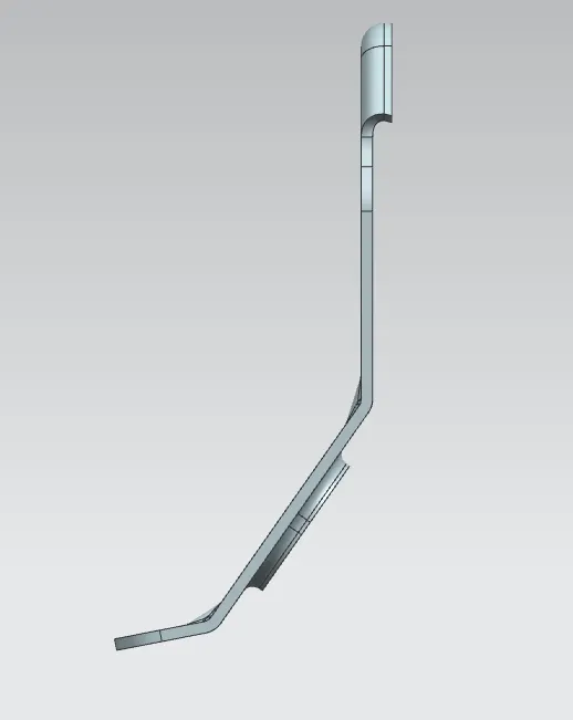
FRONT VIEW :
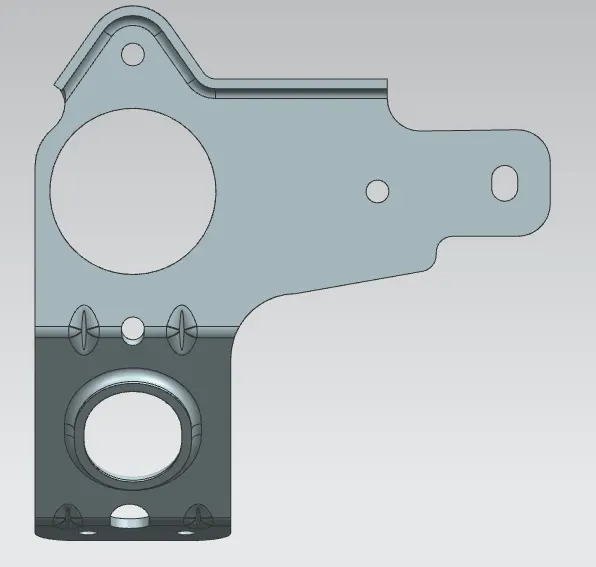
SIDE VIEW :
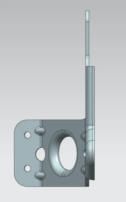
TOP VIEW :
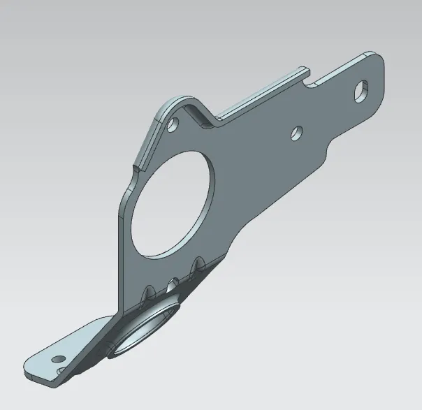
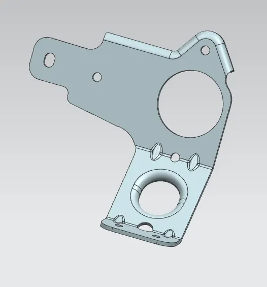
ISOMETRIC VIEW :
CONCLUSION :
In this project we learn how to operate complex sketch in sheet metal to form a component. Finally a complex sheet metal bracket part has been created.