Design of Metal bracket-II
ADVANCED SHEET METAL DESIGN USING NX CAD IN BRACKET II DESIGN
OBJECTIVE:
Main objective of the project is to Model a Bracket II design in NX cad Sheetmetal workbench, and Drafting sheet. Also learn about Advanced Sheetmetal features to the bracket II design.
SOFTWARE USED: NX 12.0
- To design the Sheetmetal Bracket II in NX by using some advanced features of Sheetmetal.
- NX Software is a flexible and powerful integrated solution that helps you deliver the products faster and efficiently way.
- NX Cad software is widely used in automotive, aviation, marine industry, thermal power station. Because of it is having modelling, drafting and manufacturing workbench.
INTRODUCTION:
- Let’s get started how NX Cad software performing in Sheetmetal application. Sheetmetal fabrication is the process of forming metal sheets to the desired shape of the components using different types of manufacturing application.
- Sheetmetal fabrication is the process of forming parts from a metal sheet by punching, cutting, stamping, and bending.
- 3D files are converted to machine codes to control the machine movement to create the desired shape of the component.
- There are different types of material are used in this fabrication process, such as ALUMINIUM, BRASS, COPPER, STEEL, TIN.
- Sheet metal parts are known for their durability, which makes them great for durability, which makes them great for end use applications.
- Because parts are formed from a single sheet of metal, designs must maintain a uniform thickness.
- 7.Be sure to follow the design requirements and tolerances to ensure parts fall closer to design intent and cutting sheets of metal.
DESIGN METHOLOGY: (BRACKET II DESIGN)
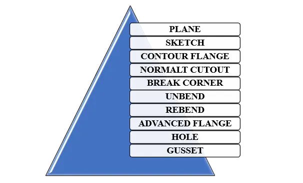
DESCRIPTION:
Bracket II creating to help of above mentioned featured. While designing the Bracket II model in Sheetmetal workbench there are some advanced features are used to Create the model.
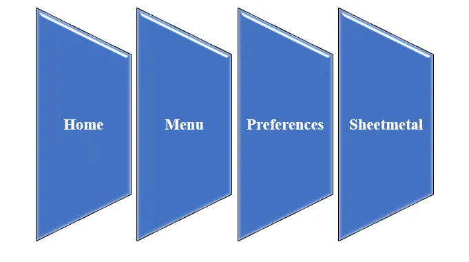
SKETCH:
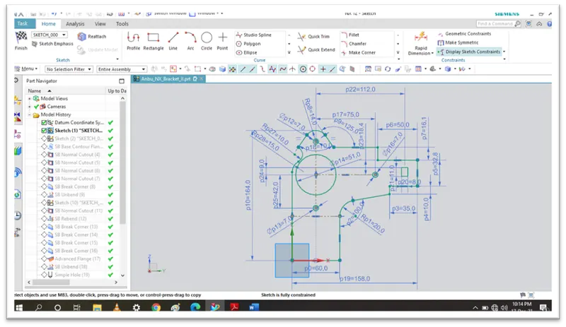
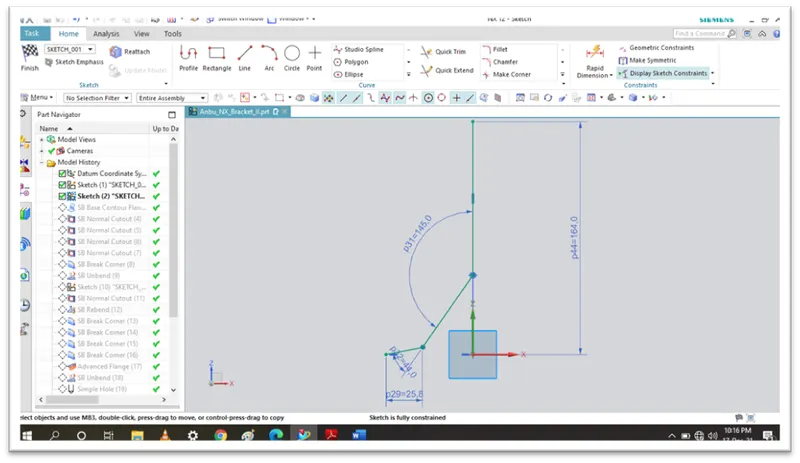
Sketch is used for creating the model by specifying the shape and dimensions.
SKETCH EXPLANATION:
- In this model we want to create a Contour flange, so that why we are creating the sketch option.
- User defined sketch is using in this contour flange feature.
- First step to create the sketch in YZ Plane. And then add another sketch in XZ Plane.
- Add multiple dimensions to ensure the sketch in fully defined sketch and then add upcoming feature.
CONTOUR FLANGE:
Creating a base feature by extruding a sketch along a vector, or adds material by sweeping a sketch along an edge or chain of edges.
CONTOUR FLANGE FEATURE EXPLANTION:
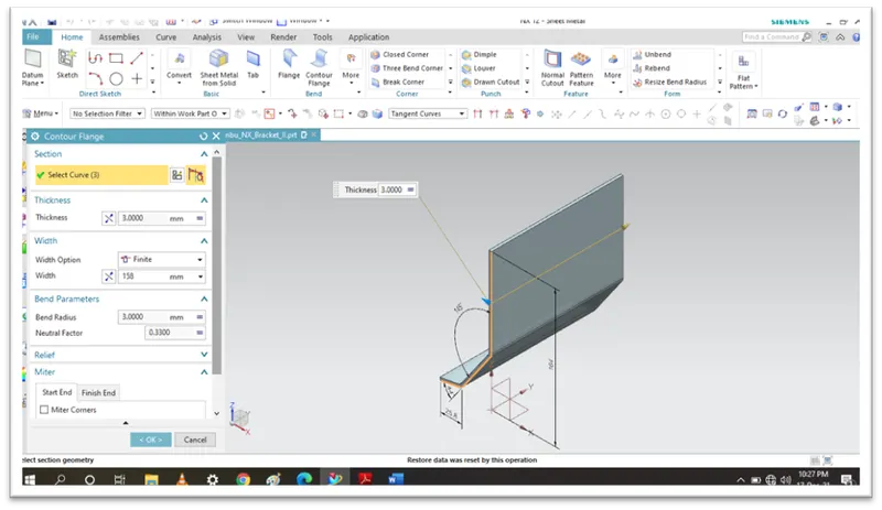
- In this project we are creating the sketches in two planes, so first select the XZ Plane sketch to create the contour flange.
- Give the dimension for contour flange feature in thickness(3mm), width option(finite), width(158mm), bend radius(3mm).
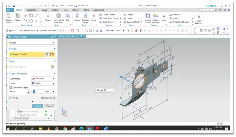
NORMAL CUTOUT:
Using the normal cutout option, it is used to remove the material from projecting a sketch onto the intersecting model.
NORMAL CUTOUT FEATURE EXPLANATION:
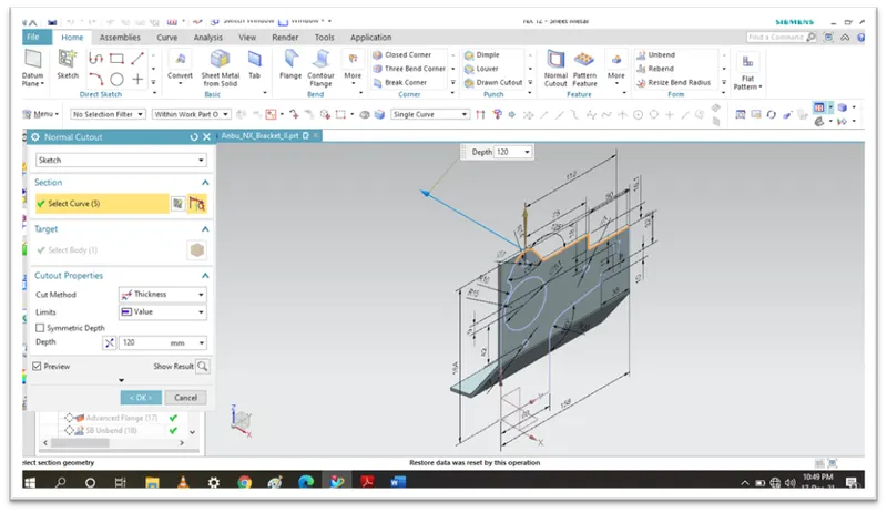
- Select the sketch and give the single curve option. Instead of then its take whole sketch.so decide to give required sketch to perform
- In normal cutout feature, specify the depth value(120mm), if it is wrong direction to make it reverse direction to make the cut the material in right position.
- In sketch it always material cut option is upward direction make it is cut as possible.
1.Cut method(thickness), limits(value), depth(120mm).
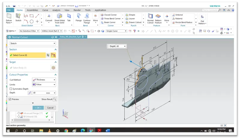
2.Cut method(thickness), limits(value), depth(49mm).
3.Cut method(thickness), limits(value), depth(120mm).
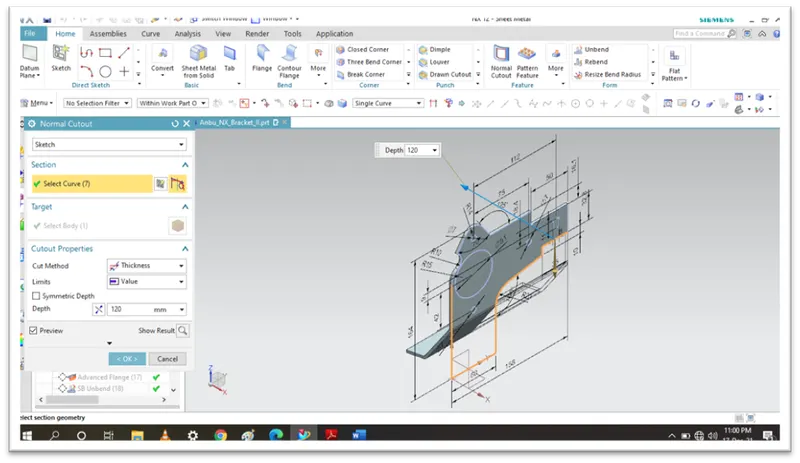
4.Cut method(thickness), limits(value), depth(60mm).
BREAK CORNER:
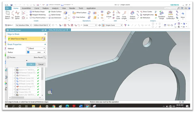
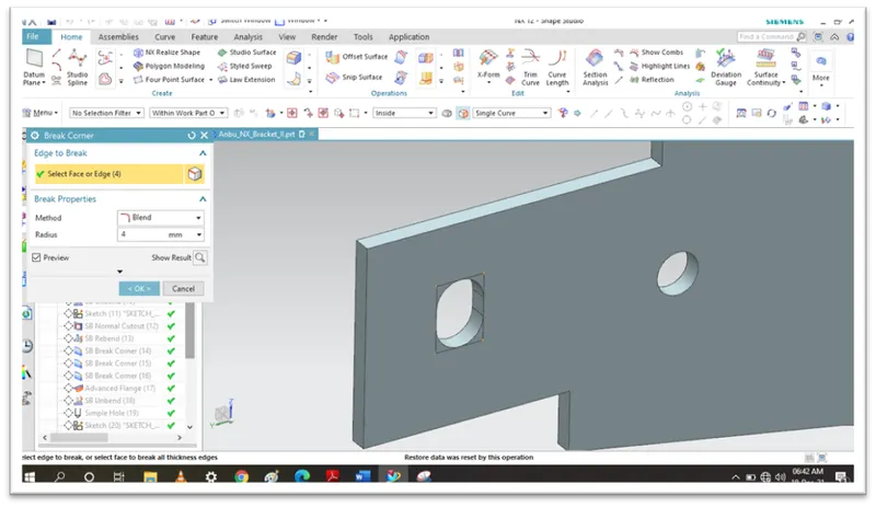
Round or chamfers a sharp corner of the tab or flange feature.
BREAK CORNER FEATURE EXPLNTION:
- Break corner option (Blend) just create the round shapes in edges.
- Click the break corner feature and which edges you want to modify the round shape.
1.Add the dimension of radius(4.5mm).
2.Add the dimension of radius(4mm).
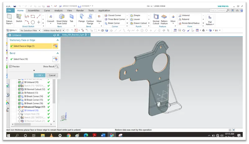
UNBEND:
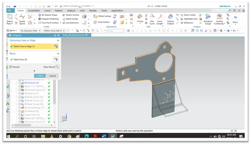
Unbend feature is used to unbend the bended region in NX Sheetmetal workbench.
UNBEND FEATURE EXPLANATION:
- Unbend feature is to create the flattens the Bracket II Sheetmetal.
- If the Unbend feature we are using it will Flattens the Sheetmetal and adjacent to the bend.
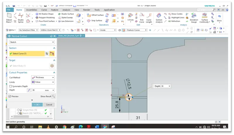
NORMAL CUTOUT:
Draw a circle and add the normal cutout feature to cut the material from Bracket II
Cut method(thickness), limits(value), depth(36mm).
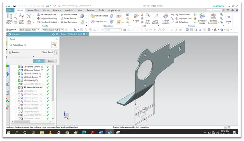
REBEND:
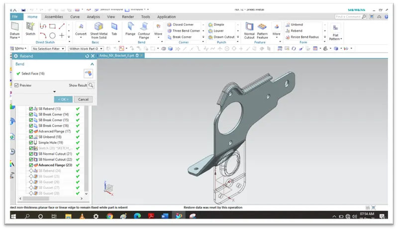
REBEND option is used to unbend feature to its previous bent state, along with any feature added after the unbend feature.
REBEND FEATURE EXPLANATION:
- It is just Restores an unbend features to its previous bend state.
- And it is including to the any feature added to after the unbend feature.
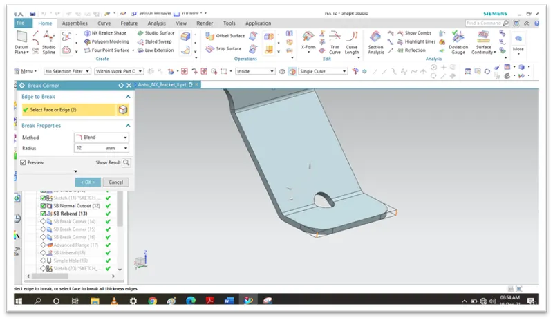
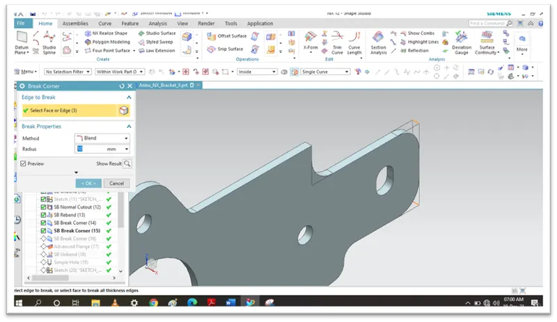
BREAK CORNER:
Add the dimension of radius(12mm).
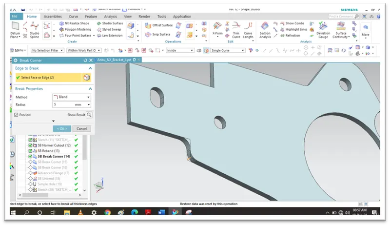
Add the dimension of radius(5mm).
Add the dimension of radius(10mm).
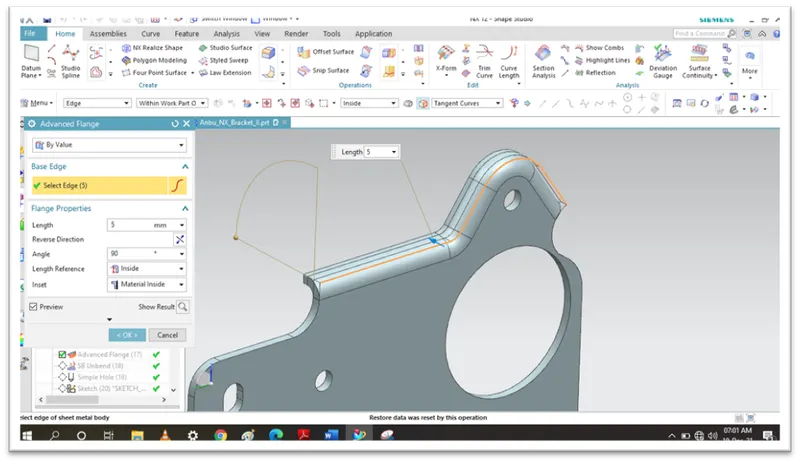
ADVANCED FLANGE:
Adds a flange along an edge using bend angle or reference face. The edge and reference face can be curved.
ADVANCED FLANGE FEATURE EXPLANATION:
- Advanced flange feature we have two Option for creating the flange, there are value and reference face.
- In this model we are creating the advanced flange feature in value method.
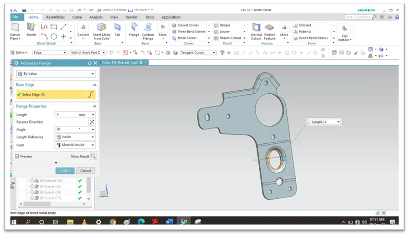
- Select the edges, Length(5mm), Angle (90), Length reference (Inside), inset (Material inside).
UNBEND:
Add the Unbend feature
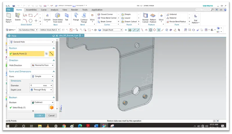
HOLE:
To create the holes in two corner Region.
HOLE FEATURE EXPLANATION:
- We need to first assign the point to specify the position of the hole.
- Then click the hole feature and specify the which type of hole you want to select the general hole option.
- And select the option of hole feature, direction (normal to face), form(simple), Screw type (general hole), Diameter(6mm), Depth limit (through body), Boolean (subtract).
- After to click ok.
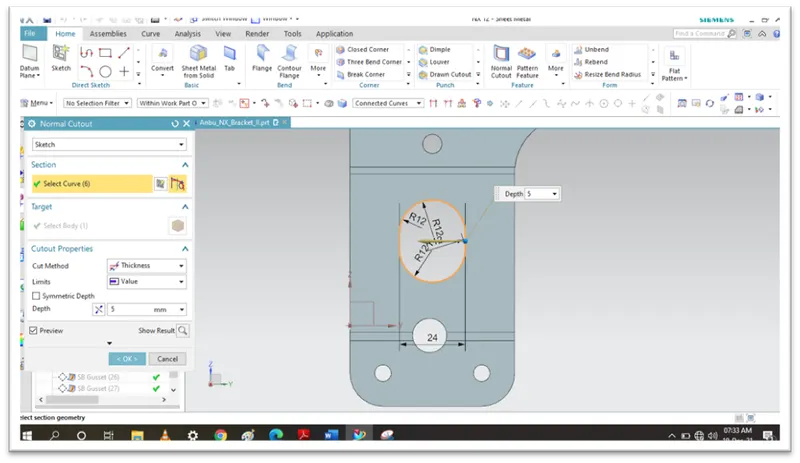
NORMAL CUTOUT:
Draw a sketch and add the normal cutout feature to cut the material from Bracket II
Cut method(thickness), limits(value), depth(5mm).
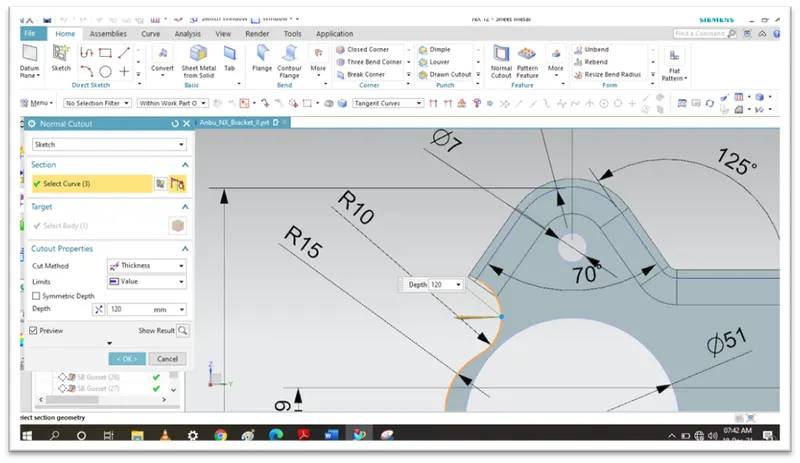
Using previous sketch and add the normal cutout feature to cut the material from Bracket II
Cut method(thickness), limits(value), depth(120mm).
ADVANCED FLANGE:
To add advanced flange feature (value method), dimension of Length(4mm), Angle (90), Length reference (Inside), Inset (Material inside).
REBEND:
Add the REBEND feature
GUSSET:
Creates a stiffening gusset on the part.
GUSSET FEATURE EXPLANATION:
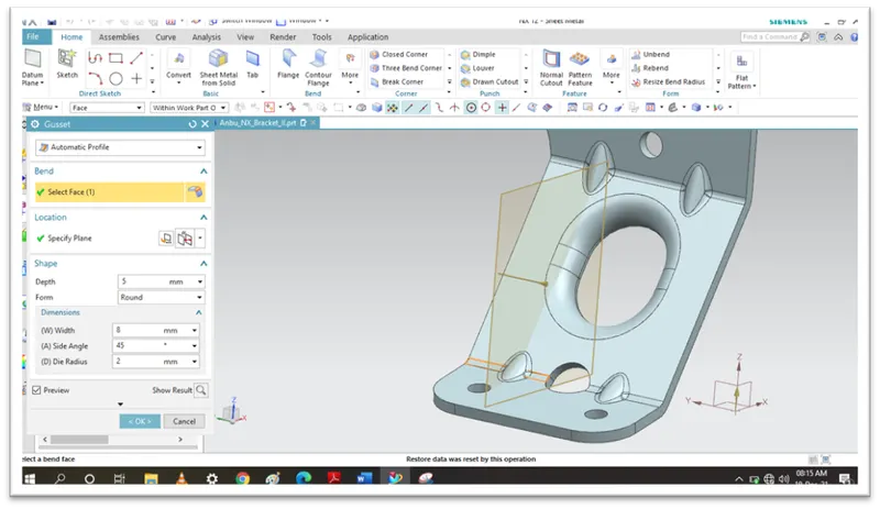
- In gusset feature we having two types of option, there are automatic method and used defined.
- Now we are using the automatic method to create a gusset, select the bend.
1.Specify the plane location (-15mm), depth (5mm), form (round), width(8mm), side angle (45), die radius (2.5mm).
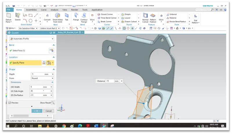
2.Specify the plane location (-15mm), depth (5mm), form (round), width(8mm), side angle (45), die radius (2.5mm).
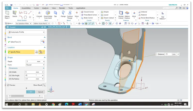
3.Specify the plane location (-15mm), depth (5mm), form (round), width(8mm), side angle (45), die radius (2mm).
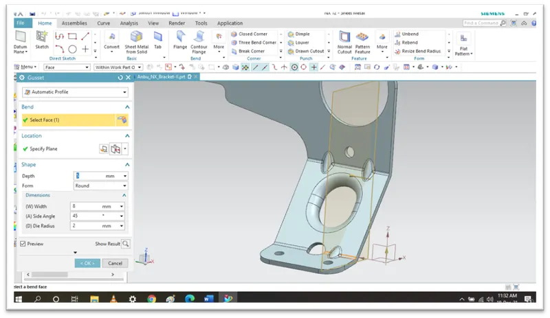
4.Specify the plane location (-15mm), depth (5mm), form (round), width(8mm), side angle (45), die radius (2mm).
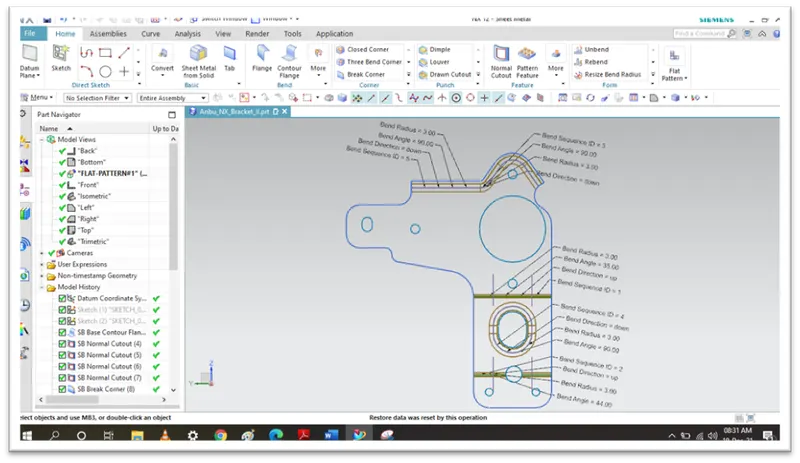
FLAT PATTERN:
Flat pattern is used to create the Bracket to formed Sheetmetal part.
FLAT PATTERN FEATURE EXPLANATION:
- It is created the drafting of the Sheetmetal design in Bracket II.
- And it is show feature names to which feature you are using to create the model.
BRACKET II VIWES:
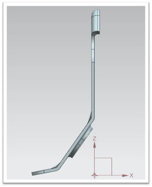
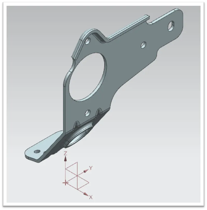
1.FRONT VIEW:
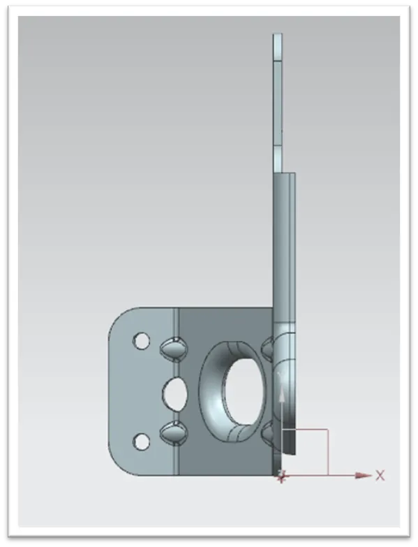
2.TOP VIEW:
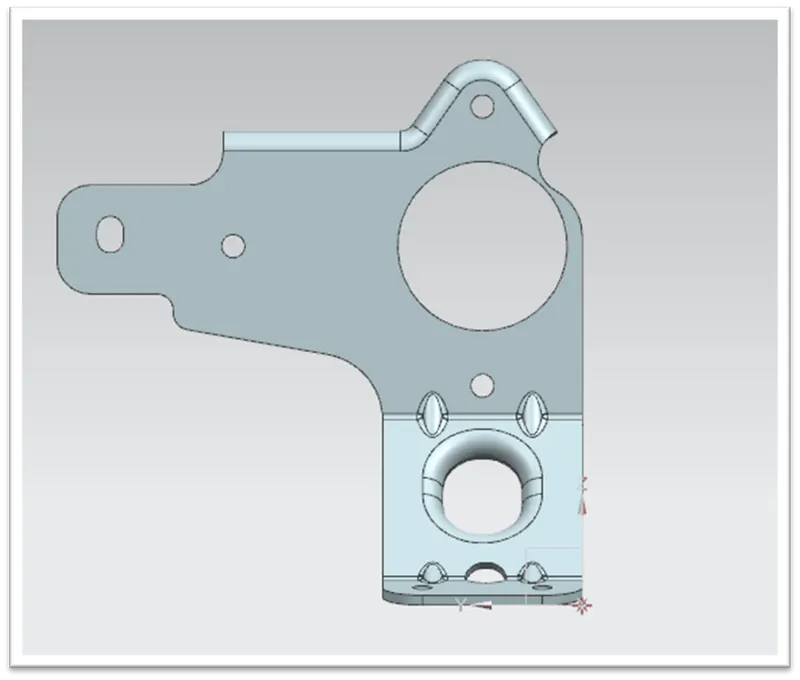
3.LEFT VIEW:
4.ISOMETRIC VIEW:
DRAFTING:
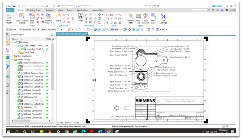
We can create the 2D Drawing sheet from Bracket II model in NX Cad software.
DRAWING SHEET:
- Drawing sheet is used to represent the Sheetmetal model in 2D view(A4) help of NX cad platform.
- It is show the which feature you are using in this Bracket II
DETAILED VIEW:
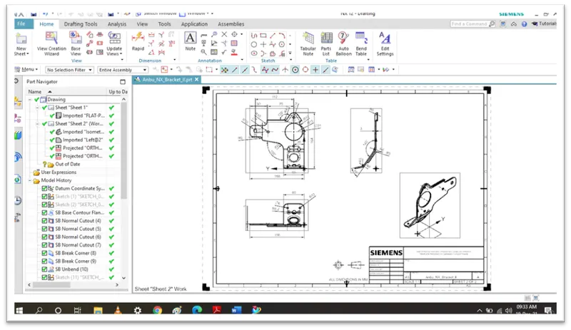
- Detailed view is nothing but it is just Show the recommended view from the model in single sheet(A4).
- You will see the detail view in A4 size sheet top, right, front, isometric views in detailed view for Bracket II.
CONCLUSION:
- This project creating the Bracket II Sheetmetal design using NX Cad Siemens 12.0 version platform.
- In this model Sheetmetal Advanced feature and tools are learning in this project.
- Designing the Sheetmetal in NX cad software, it is user friendly interface for Creating the Bracket II design in NX.