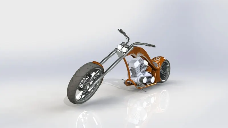
Design of American Chopper
MODELLING AND RENDERING OF AMERICAN CHOPPER USING SOLIDWORKS
OBJECTIVE:
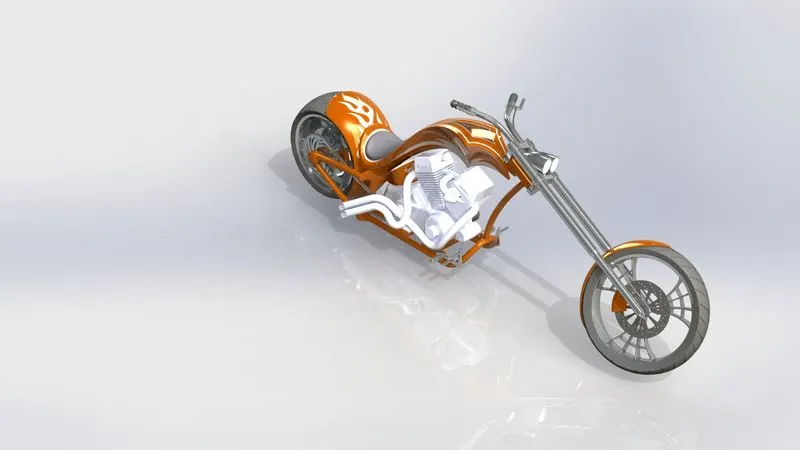
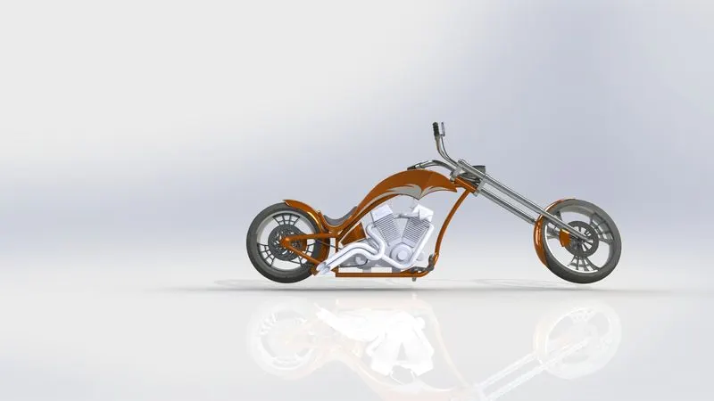
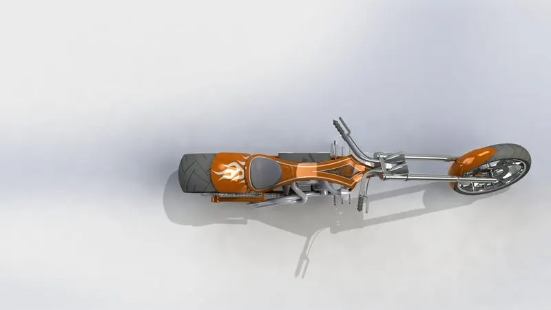
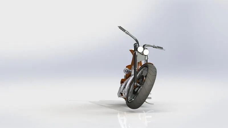
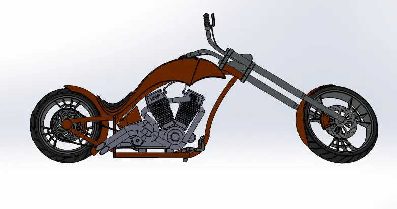
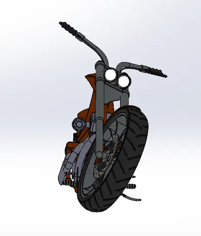
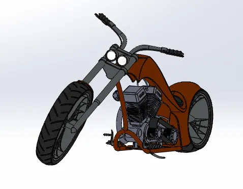
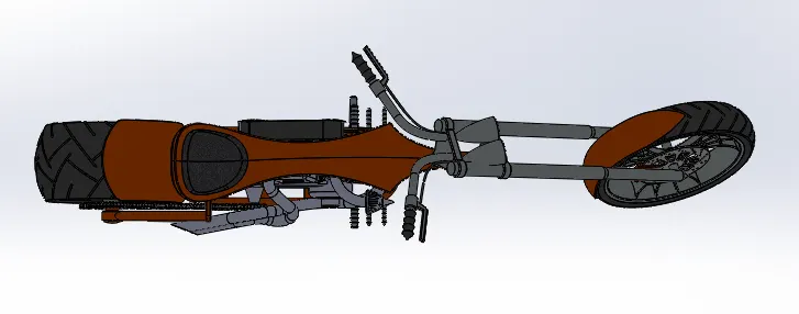
The objective of the project is used to create the modelling, assembling and rendering of American Chopper using SOLIDWORKS software.
INTRODUCTION:
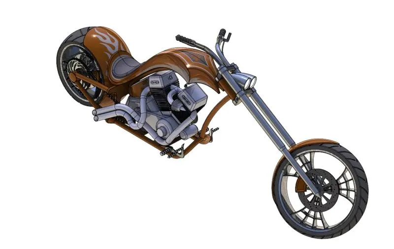
In this project we will learn about the Design, Assemble and Rendering of the American chopper bike. I am using the SOLIDWORKS VISUALIZE Application, because of it is show the assembly model in more realistic.
DESIGN METHODOLOGY:
I have created the assembly of American chopper with “Bottom Up” approach. Following steps are used to create the model.
1.Designing of American chopper Parts.
2.Assembling the American chopper Parts.
3.Applying the Decals, Scene, Camera setup Environment.
4.Finally Rendering the American chopper model.
Designing of the American chopper are Consists of the Following 13 individual parts,
1.Transmission Belt
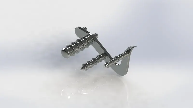
2.Kickstand
3.Chain
4.Front Fender
5.Rear Fender
6.Oil Tank
7.Pedal
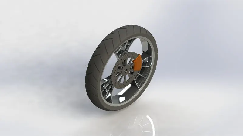
8.Front-Wheel
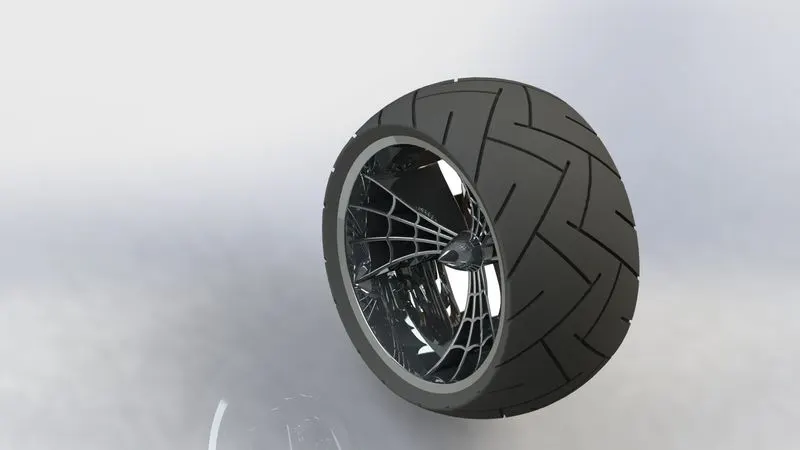
9.Rear-Wheel
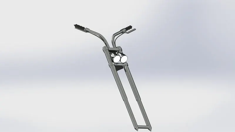
10.Front-Fork
11.Gas Tank
12.Chassis
13.Engine
I would like to tell how to create modelling, assembling, Rendering to the American chopper Model. Before starting the part, you should create the template with required Units, Planes, Settings in it and use for all models.
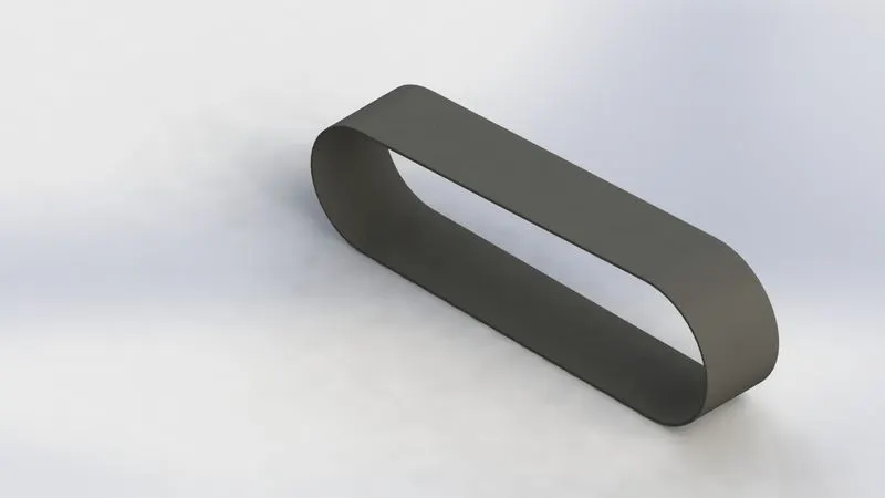
- TRANSMISSION BELT:
A Belt is a loop of flexible material used to link two or more rotating shaft mechanically, most often parallel. Belts may be used as source of motion, to transmit power efficiently or to track relative moment.
DESCRIPTION OF TRANSMISSION BELT:
SKETCH - Create a new sketch or edit the existing sketch, also includes the command of line, circle, arc, slot, spline, etc.
OFFSET - Offset the entities with specify distance.
BOSE EXTRUDE - Extrude a sketch or selected sketch contours into create the solid feature.
FILLET - Create a rounded internal or external face along edges on a solid or surface feature.
APPEARANCE - Transmission Belt - Matte Rubber
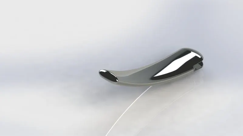
- KICKSTAND:
A kickstand is a device on a bicycle or motorcycle that usually a piece of metal that flips down from the frame and makes contact the ground.
DESCRIPTION OF KICKSTAND:
SKETCH - Create a new sketch or edit the existing sketch, also includes command of line, circle, spline, slot, etc.
LOFT - Add material between 2 or more profile to create a solid feature.
DOME - Add one or more domes to selected planer or non-planer faces.
CUT EXTRUDE - Cut a solid model by extruding a sketched profile in one or two directions.
SPLIT - Creates multiple bodies from single body.
BOSS EXTRUDE - Extrude a sketch or selected sketch contours into create the solid feature.
FILLET - Create a rounded internal or external face along edges on a solid or surface feature.
APPEARANCE - Kickstand - Chrome steel
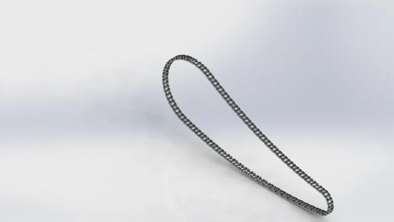
- CHAIN:
Chain drive is a way of transmitting mechanical power from one place to another. It is often used to convey power to the wheels of a vehicle, particularly bicycles and motorcycles. It is also used in a wide variety of machines besides vehicles.
DESCRIPTION OF CHAIN:
SKETCH - Create a new sketch or edit the existing sketch, also includes command of line, circle, spline, slot, etc.
BOSS EXTRUDE - Extrude a sketch or selected sketch contours into create the solid feature.
BLOCKS – Create a New Blocks to the sketch drawing.
CIRCULAR PATTERN – Pattern features, faces & bodies round the selected axis.
FILLET - Create a rounded internal or external face along edges on a solid or surface feature.
BODY KEEP/DELETE – Deletes or keeps one or more solid or surface bodies.
MIRROR – Mirror features, faces & bodies about a plane.
APPEARANCE – Chain - Chrome steel
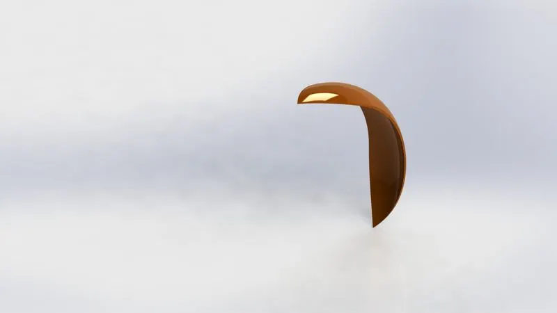
- FRONT FENDER:
Fenders are what will keep you from having a skunk stripe on your backside if you ride in the rain, and a front fender will help protect your feet and ankles from spray if you're riding in the rain or even through a puddle.
DESCRIPTION OF FRONT FENDER:
SKETCH - Create a new sketch or edit the existing sketch, also includes command of line, circle, spline, slot, etc.
OFFSET - Offset the entities with specify distance.
EXTENDED ENTITIES - Extended a Sketch entities to meet another sketch entities.
TRIM ENTITIES – Delete the selected sketch entities.
REVOLVE - To create a revolve feature: Create a sketch that contains one or more profiles and a centerline, line, or edge to use as the axis around which the feature revolves.
DYNAMIC MIRROR – Mirror entities dynamically about the centerline.
SPLIT - Creates multiple bodies from single body.
FILLET - Create a rounded internal or external face along edges on a solid or surface feature.
APPEARANCE – Front Fender - Painted Siena
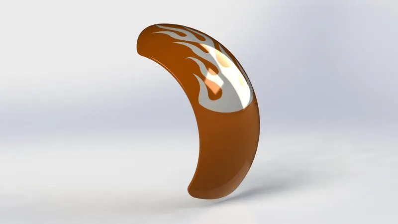
- REAR FENDER:
If you plan to ride during and after a rain shower, fenders will keep your back and your gear dry. If you ride on wet roads with no rain, fenders save you weight because your clothes stay dry.
DESCRIPTION OF REAR FENDER:
SKETCH - Create a new sketch or edit the existing sketch, also includes command of line, circle, spline, slot, etc.
OFFSET - Offset the entities with specify distance.
EXTENDED ENTITIES - Extended a Sketch entities to meet another sketch entities.
TRIM ENTITIES – Delete the selected sketch entities.
REVOLVE - To create a revolve feature: Create a sketch that contains one or more profiles and a centerline, line, or edge to use as the axis around which the feature revolves.
DYNAMIC MIRROR – Mirror entities dynamically about the centerline.
SPLIT - Creates multiple bodies from single body.
FILLET - Create a rounded internal or external face along edges on a solid or surface feature.
APPEARENCE – Painted Siena
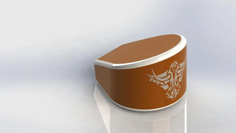
- OIL TANK:
A hollow part which stores oil to run the engine with minimum thickness.
DESCRIPTION OF OIL TANK:
SKETCH - Create a new sketch or edit the existing sketch, also includes command of line, circle, spline, slot, etc.
BOSS EXTRUDE - Extrude a sketch or selected sketch contours into create the solid feature.
COMBINE – Combine the two or more solid bodies.
FILLET - Create a rounded internal or external face along edges on a solid or surface feature.
APPEARANCE – Painted Siena.
- PEDAL:
Pedal which allows you to use safety and for you to step on for long time.
DESCRIPTION OF PEDAL:
SKETCH - Create a new sketch or edit the existing sketch, also includes command of line, circle, spline, slot, etc.
BOSS EXTRUDE - Extrude a sketch or selected sketch contours into create the solid feature.
REVOLVE - To create a revolve feature: Create a sketch that contains one or more profiles and a centerline, line, or edge to use as the axis around which the feature revolves.
LINEAR PATTERN – Pattern features, faces& bodies in one or two linear directions.
DOME - Add one or more domes to selected planer or non-planer faces.
FILLET - Create a rounded internal or external face along edges on a solid or surface feature.
CHAMFER – Creates a sloping surfaces at the edge, chain of tangent edges or the vertex.
APPEARANCE – Chrome steel
- FRONT-WHEEL:
Wheel is a circular part which helps to move forward to the vehicle from one place to another place with easy method.
DESCRIPTION OF FRONT-WHEEL:
SKETCH - Create a new sketch or edit the existing sketch, also includes command of line, circle, spline, slot, etc.
REVOLVE - To create a revolve feature: Create a sketch that contains one or more profiles and a centerline, line, or edge to use as the axis around which the feature revolves.
BOSS EXTRUDE - Extrude a sketch or selected sketch contours into create the solid feature.
CUT EXTRUDE - Cut a solid model by extruding a sketched profile in one or two directions.
CUT REVOLVE – Cuts a solid model by 360 degree by using the axis.
CIRCULAR PATTERN – Pattern features, faces & bodies round the selected axis.
COMBINE – Combine the two or more solid bodies.
FILLET - Create a rounded internal or external face along edges on a solid or surface feature.
CHAMFER – Creates a sloping surfaces at the edge, chain of tangent edges or the vertex.
APPEARANCE –
RIM – Chrome steel
ROTOR – Carbon steel
CALIPER – Painted siena
TYRE – Matte rubber
- REAR WHEEL:
Rear wheel is a circular part which helps to move forward to the vehicle from one place to another place with attached to the caliper and disc.
SKETCH - Create a new sketch or edit the existing sketch, also includes command of line, circle, spline, slot, etc.
BOSS EXTRUDE - Extrude a sketch or selected sketch contours into create the solid feature.
REVOLVE - To create a revolve feature: Create a sketch that contains one or more profiles and a centerline, line, or edge to use as the axis around which the feature revolves.
CUT EXTRUDE - Cut a solid model by extruding a sketched profile in one or two directions.
CUT REVOLVE – Cuts a solid model by 360 Degree by using the axis.
CIRCULAR PATTERN – Pattern features, faces & bodies round the selected axis.
COMBINE – Combine the two or more solid bodies.
FILLET - Create a rounded internal or external face along edges on a solid or surface feature.
CHAMFER – Creates a sloping surfaces at the edge, chain of tangent edges or the vertex.
APPEARANCE –
RIM – Chrome steel
ROTOR – Carbon steel
CALIPER – Painted siena
TYRE – Matte rubber
- FRONT FORK:
A bicycle fork is the part of a bicycle that holds the front wheel. A fork typically consists of two blades which are joined at the top by a fork crown. The crown is often at the front. Most suspension forks have an arch connecting the two side of the lowers.
DESCRIPTION OF FRONT FORK:
SKETCH - Create a new sketch or edit the existing sketch, also includes command of line, circle, spline, slot, etc.
REVOLVE - To create a revolve feature: Create a sketch that contains one or more profiles and a centerline, line, or edge to use as the axis around which the feature revolves.
BOSS EXTRUDE - Extrude a sketch or selected sketch contours into create the solid feature.
CUT EXTRUDE - Cut a solid model by extruding a sketched profile in one or two directions.
CUT REVOLVE – Cuts a solid model by 360 degree by using the axis.
LINEAR PATTERN – Pattern features, faces& bodies in one or two linear directions.
FILLET - Create a rounded internal or external face along edges on a solid or surface feature.
DOME - Add one or more domes to selected planer or non-planer faces.
BODY MOVE/BODY – Move, copies and rotate solid& surface bodies.
PROJECT CURVE – Project the sketched curves onto a curve.
BOSS SWEEP – Sweep a closed profile along on an open or closed path to create a Solid Features.
MIRROR – Mirror features, faces, and bodies about a plane.
COMBINE – Combine the two or more solid bodies.
APPEARANCE –
FORK – Chrome steel
HANDLE GRIP AND BRAKE WIRES – Matte rubber
HEAD LAMP – Light glass
- GAS TANK:
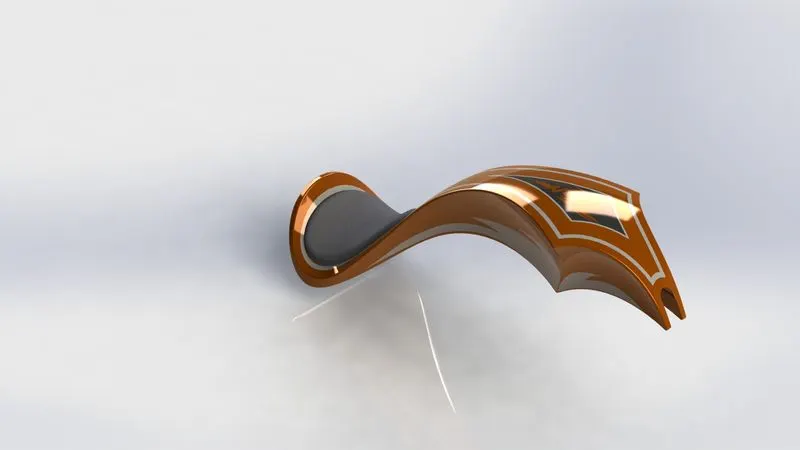
A fuel tank is a safe container for flammable fluids and it stored the fuel supply into an engine.
DESCRIPTION OF GAS TANK:
SKETCH - Create a new sketch or edit the existing sketch, also includes command of line, circle, spline, slot, etc.
SURFACE SWEEP – Sweep a closed profile along on an open or closed path to create the surface features.
SURFACE TRIM – Trim where the surface Interact with another surface.
SURFACE LOFT – Creates a lofted surfaces Interact with another surface.
SURFACE BOUNDARY – Creates a surface between profile that are tangent or curvature continuous in all directions.
MIRROR – Mirror features, faces, and bodies about a plane.
SURFACE KNIT – Combine two or more adjacent and non-intersecting surfaces into a single surface body.
SPLIT LINE – Projects the sketch to curved and creating multiple separate faces.
SURFACE EXTRUDE – Extrude a sketch or selected sketch contours in one or two directions to create a surface Features.
PROJECT CURVE – Project the sketched curves onto a curve.
FILLET - Create a rounded internal or external face along edges on a solid or surface feature.
CUT SWEEP – Cuts a solid model by sweeping a closed profile along an open or closed path.
SHELL – Hollow a selected body, creating the Thin-walled features.
APPEARANCE –
TANK – Painted Siena
SEAT - Fabric
- CHASSIS:
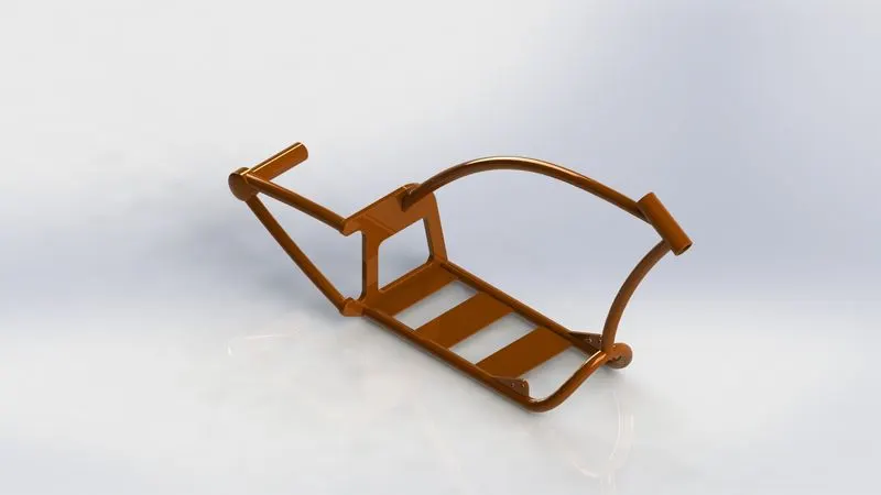
Chassis is the supporting structure of the vehicle which is also known as a frame of the body. It is with stand the both static and dynamic conditions.
DESCRIPTION OF CHASSIS:
SKETCH - Create a new sketch or edit the existing sketch, also includes command of line, circle, spline, slot, etc.
PROJECT CURVE – Project the sketched curves onto a curve.
BOSS EXTRUDE - Extrude a sketch or selected sketch contours into create the solid feature.
CUT EXTRUDE - Cut a solid model by extruding a sketched profile in one or two directions.
BOSS SWEEP – Sweep a closed profile along on an open or closed path to create a Solid Features.
MIRROR – Mirror features, faces, and bodies about a plane.
REVOLVE - To create a revolve feature: Create a sketch that contains one or more profiles and a centerline, line, or edge to use as the axis around which the feature revolves.
APPEARANCE – Painted Siena
- ENGINE:
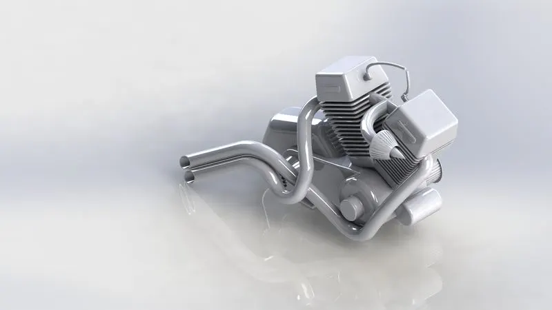
An engine is a heart of bike, it is Convert heat energy into mechanical energy by use of petrol or diesel.
DESCRIPTION OF ENGINE:
SKETCH - Create a new sketch or edit the existing sketch, also includes command of line, circle, spline, slot, etc.
BOSS EXTRUDE - Extrude a sketch or selected sketch contours into create the solid feature.
REVOLVE - To create a revolve feature: Create a sketch that contains one or more profiles and a centerline, line, or edge to use as the axis around which the feature revolves.
CIRCULAR PATTERN – Pattern features, faces & bodies round the selected axis.
LINEAR PATTERN – Pattern features, faces& bodies in one or two linear directions.
DOME - Add one or more domes to selected planer or non-planer faces.
FILLET - Create a rounded internal or external face along edges on a solid or surface feature.
CHAMFER – Creates a sloping surfaces at the edge, chain of tangent edges or the vertex.
CUT EXTRUDE - Cut a solid model by extruding a sketched profile in one or two directions.
MIRROR – Mirror features, faces, and bodies about a plane.
SPLIT - Creates multiple bodies from single body.
PROJECT CURVE – Project the sketched curves onto a curve.
COMPOSITION CURVE – Combine selected edges, curves and sketches into a single curve.
SWEEP EXTRUDE – Sweep a closed profile along an open or closed path to create a Solid Features.
COMBINE – Combine the two or more solid bodies.
APPEARANCE – Chrome steel
ASSEMBLY OF AMERICAN CHOPPER:
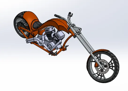
All the Models parts are inserted in the assembly section by using the command insert components. The parts are assembled together with help of planes and mates.
MATES:
Create geometric relation between the component, To define the allowable direction of linear or rotational motion to the parts.
CONCULATION:
I have completed my Modelling and Rendering of American Chopper using SOLIDWORKS and SOLIDWORKS VISUALIZE software. It is wonderful experience using SOLIDWORKS.