Advanced Sheet Metal Design Using NX Cad Challenge_7_ Metal bracket-II
SHEET METAL BRACKET II USING NX
OBJECTIVE :
The objective of this project which make a sheet metal bracket which including gusset and advanced flange proces. By using gusset to provide a extra stiffening for the metal bracket increase durability of the bracket.
INTRODUCTION :
Sheet metal defines us the thin sheet which made by alloys according to needed parameters. Those sheet undergoes bending, forming, cutting, enclosing etc.,
Sheet metal usage increasing everyday to day life including kitchen appliances to rocket spacing every its used to fabrication of surfaces in every industries. Thin sheet metals are also known as coils and foils.
Sheet metal plays a major role in automotive industries for making surfaces of every automobiles.
Siemens Nx formely unigraphics is a powerfull CAE/CAM/CAD tools used for every phase of engineering including design, analysis, manufacturing, a class surface design.
DESIGN APPROACH/METHODOLOGY :
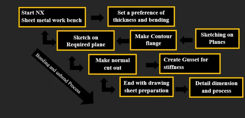
The design approach is sheet metal design in NX sheet metal workbench.
FEATURES AND TOOLS USED FOR DESIGN :
SKETCH TOOLS :
- Line tool - Line tool is used to create a straight line according to coordinate system.
- Rectangle - To create a rectangle on a coordinate system.
- Circle - Create a circle according to face and plane which we selected.
- Rapid dimension - Rapid dimesion is used to make dimensions for a sketch.
- Angular dimensions - Make dimension between angular coordinates.
SHEET METAL FEATURES :
- Bend - In sheet metal basic principle is to be bending and unbend for the case bend feature used to make bend in sheet metal according to sketch.
- Normal cutout - It is used to make cut out using given diagram.
- Break corner - command used for making a fillet at the sharp edge corner sheet metal.
- Contour flange - Its a command used to make a sheet metal extrusion by using defined sketch as per requirement.
- Advanced flange - It is used to make flanges in a complex area of sheet metal design.
- Unbend - It is used to make a flat sheet metal features which we make.
- Hole - Hole feature is used to create holes in the parts or components like countersink, counterbore, threaded bore operations.
- Gusset - Creating gusset is a stiffening process which provide in between two bend hinges for extra durability.
- Flat pattern - It is used to create a flat pattern according to the flat surfaces which we selected.
PROCEDURE FOR DESIGN OF METAL BRACKET II :
- Create a sketch in Zx coordinate system after that make a contour flange.
- In before all to create preferences about making a sheet thickness and bend radius according to purpose.
- Followed with contour flange in reference as front plane create a drafting as per sketch for normal cut out for making bracket.
- Using normal cut out command make cutout according to requirement.
- Unbend the bracket make hole as per requirement using hole command.
- As reference of bend make gusset by selecting plane and make a manual adjustment as per requirement of gusset for stiffening.
- Make it unbend while unbend the gusset feature is not shown.
- Followed with drafting unbend the sheet create a bead and make it unbend.
- Prepare a drawing sheet for manufacturing process.
Finishing all the steps create a flat pattern option feature to make flat view
DRAFTING A SKETCH :
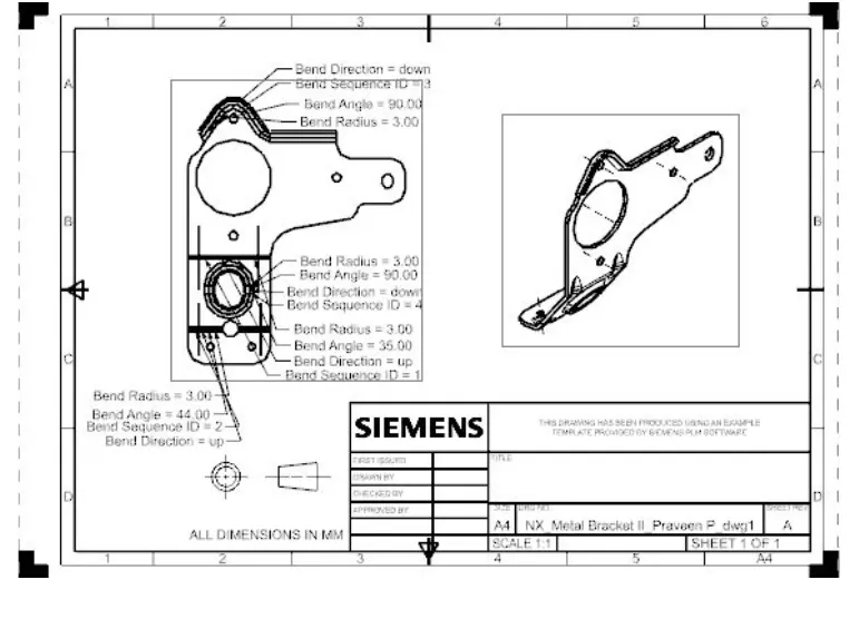
Import a flat pattern view to the A4 drawing sheet in NX. In orient view make flat pattern view fixed with the sheet by rotation.
After making drafting save the sheet.
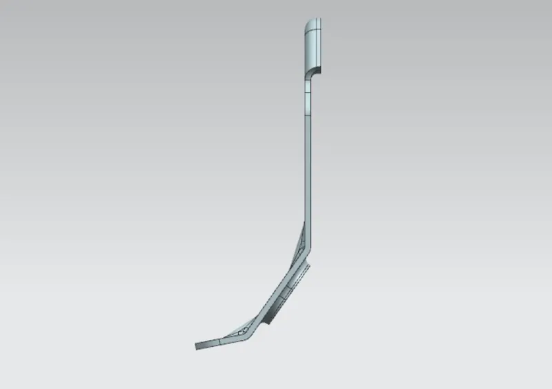
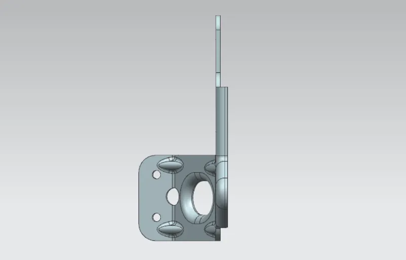
STANDARD VIEWS OF MODELLING :
FRONT VIEW :
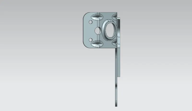
RIGHT SIDE VIEW :
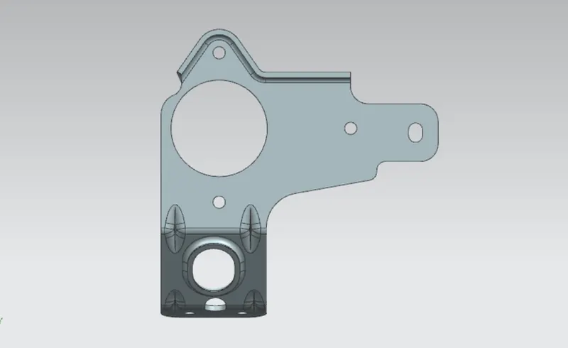
TOP VIEW :
BOTTOM VIEW :
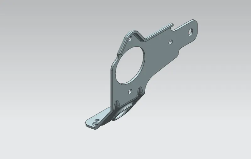
ISOMETRIC VIEW :
DETAILED DRAWING SHEET OF MODEL :
CONCLUSION :
End of the project have a hands on experience about creating sheet metal bracket with technical parameters needed to consider.