Advanced Sheet Metal Design Using NX Cad Challenge_2_Box Assembly
ADVANCED SHEET METAL DESIGN OF BOX ASSEMBLY USING NX
OBJECTIVE :
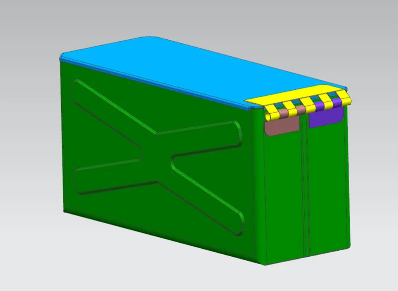
To design a box assembly using NX sheet metal application as shown in the figure.
INTRODUCTION :
The sheet box structure design is obtained using sheet metal application NX12. Various features such as flange, tab, dimple is used while creating the above model.
METHODOLOGY :
STEP-1 : Create a tab.
STEP-2 : Create bends on each side of the sheet.
STEP-3 : Create flanges on both the sides (hem flange)
STEP-4 : Mirror the body with respect to the required axis.
STEP-5 : Create sketch on a plane with particular offset from base and create a tab.
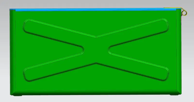
STEP-6 : Create a dimple with sketch on either side of the box.
STEP-7 : Unbend the sheet.
STEP-8 : Create sketch for the hinge and normal cut the profile.
STEP-9 : Re bend the sheet.
STEP-10 : Create beads at the bottom for support.
DESCRIPTION AND COMMANDS USED :
TAB : It is used to create the base feature of a sheet metal.
FLANGE : It is used to create an extended feature for the sheet metal.
SKETCH : Its a basic drawing in which any kind of operation can be performed with reference to it.
UNBEND : It is a command which is used to unbend the sheet metal with respect to a stationary face.
DIMPLE : It is used to create pitch down or pitch up on a surface with the help of a sketch.
REBEND : It is used to bring back the old bends which were bent before.
BEADS : Used for giving more strength for the sheet metal.
MIRROR FEATURE : It is used to create the same replica of the selected features with respect to an axis.
VIEWS :
FRONT VIEW :
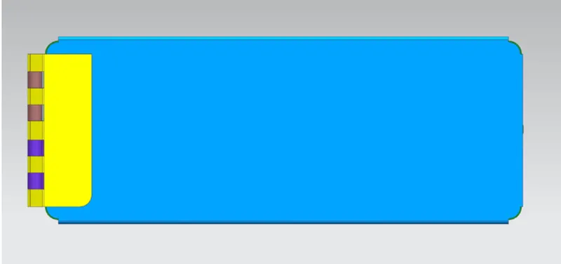
TOP VIEW :
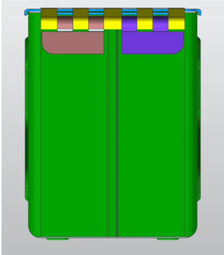
SIDE VIEW :
ISOMETRIC VIEW :
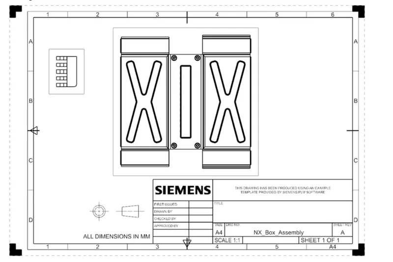
DRAWING SHEET :
CONCLUSION :
The sheet metal Box Assembly is successfully designed using NX Sheet metal workbench.